Disclosure of Invention
One of the purposes of the invention is to provide a two-stage variable oil pump adopting the joint control of a slide valve and a switch electromagnetic valve, which can ensure that only oil fed back from a main oil duct is always received in a feedback cavity, thereby improving the anti-interference capability of the system to a great extent.
In order to solve the technical problems, the invention adopts the following technical scheme: a two-stage variable oil pump jointly controlled by a slide valve and a switch electromagnetic valve comprises a pump body, a pump cover, a slide block, a rotor, a pump shaft and a main variable spring, wherein the slide block, the rotor, the pump shaft and the main variable spring are arranged in the pump body; the oil pressure control chamber is communicated with the main oil duct through a switching solenoid valve, so that oil pressure can be generated in the oil pressure control chamber to push the sliding valve to move rightwards and compress the auxiliary variable spring, or the switching solenoid valve can disconnect the connection between the oil pressure control chamber and the main oil duct, so that the auxiliary variable spring can push the sliding valve to move leftwards.
The left end of the oil pressure control cavity is provided with a guide hole for the slide valve to extend into, the outline of the outer wall of the slide valve is matched with the outline of the inner wall of the guide hole, and the right end of the main variable spring extends into the guide hole and abuts against the left end face of the slide valve.
Preferably, the side wall surface of the slide valve is provided with a guide plate in an annular mode, the inner wall of the oil pressure control cavity is provided with a limiting step, the guide plate can move rightwards under the action of oil pressure to abut against the limiting step, or the guide plate can push the slide valve to move leftwards along with the auxiliary variable spring and then abut against the left wall surface of the oil pressure control cavity.
More preferably, the left end of the oil pressure control chamber is provided with two oil inlet holes, the two oil inlet holes are symmetrically arranged on two sides of the slide valve, and an oil guide channel is connected between the two oil inlet holes.
More preferably, the right end of the spool valve is provided with a spring guide groove for the secondary variable spring to extend into.
More preferably, the stiffness coefficient of the secondary variable spring is smaller than that of the primary variable spring.
In addition, the invention also provides a two-stage variable engine oil pump system which comprises the two-stage variable engine oil pump jointly controlled by the sliding valve and the switch electromagnetic valve, wherein the low-pressure oil suction cavity is communicated with an oil pan through a strainer, an outlet of the pump body is connected with a main oil gallery through the strainer, oil in the main oil gallery enters a lubricating part of an engine and then is discharged into the oil pan, the main oil gallery is connected with the switch electromagnetic valve through an oil line, the switch electromagnetic valve is provided with an A outlet and a T outlet, the A outlet is communicated with the oil pressure control cavity, the T outlet is communicated with the oil pan, the switch electromagnetic valve can control one of the A outlet and the T outlet to be opened and the other to be closed, and the oil pressure control cavity is communicated with the oil pan through an oil discharge hole.
In the system, the pump outlet is also connected with an oil pan through a pressure relief oil path, and a cold start safety valve is arranged in the pressure relief oil path.
The working principle of the invention is as follows: when the switch electromagnetic valve is in an electrified state, oil in the main oil duct can enter the oil pressure control cavity to form pressure and push the slide valve to move rightwards to the limit position, so that the auxiliary variable spring is compressed, correspondingly, the main variable spring extends and can enable the pre-compression amount to be in the minimum state, and then the oil in the main oil duct directly entering the feedback cavity can push the slide block variable only by small oil pressure, and further the low oil pressure adjusting mode is realized.
Under the power-off state of the switch electromagnetic valve, no oil pressure exists in the oil pressure control cavity, the auxiliary variable spring can push the sliding valve to move to the limit position to the left, correspondingly, the main variable spring is compressed, so that the larger oil pressure of the main oil duct is required to enter the feedback cavity at the moment, the precompression force of the main variable spring and the auxiliary variable spring can be overcome to push the sliding block to move to carry out variable, and then the high oil pressure adjusting mode is entered.
The two-stage variable oil pump adopting the combined control of the slide valve and the switch electromagnetic valve realizes two-stage variable adjustment, has simple structure and easy realization, ensures that only oil fed back from a main oil duct needs to be received in a feedback cavity, and overcomes the defect of poor anti-interference capability of the traditional pilot two-stage variable oil pump and system.
Drawings
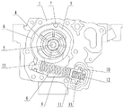
FIG. 1 is a schematic view of the overall structure within a pump body in an embodiment of the invention;
FIG. 2 is a schematic structural view of a pump body in the embodiment;
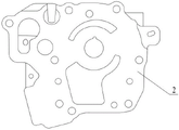
FIG. 3 is a schematic structural diagram of a pump cover in an embodiment;
FIG. 4 is a schematic structural view of a spool valve in the embodiment;
FIG. 5 is a schematic structural diagram of a two-stage variable oil pump system in a low oil pressure regulation mode according to an embodiment of the present invention;
fig. 6 is a schematic structural diagram of the two-stage variable oil pump system in the high oil pressure regulation mode according to the embodiment of the invention.
The reference signs are:
1-pump body 2-pump cover 3-slide block
4-rotor 5-pump shaft 6-main variable spring
7-rotating pin 8-feedback cavity 9-low pressure oil suction cavity
10-oil pressure control cavity 11-slide valve 12-auxiliary variable spring
13-slide block arm 14-guide hole 15-guide plate
16-oil inlet 17-oil leading channel 18-spring guide groove
19-strainer 20-sump 21-Pump Outlet
22-machine filter 23-cold start safety valve 24-switch electromagnetic valve
25-oil drain hole.
Detailed Description
In order to facilitate understanding of those skilled in the art, the present invention will be further described with reference to the following examples and drawings, which are not intended to limit the present invention.
It should be noted that, unless otherwise specifically stated or limited, the terms "mounted," "connected," "fixed," and the like are used broadly in the present invention and may be, for example, fixedly connected, detachably connected, or integrally connected. The specific meanings of the above terms in the present invention can be understood by those skilled in the art according to specific situations. Further, in the present invention, unless otherwise expressly specified or limited, the first feature "on" or "under" the second feature may comprise the first and second features being in direct contact, or may comprise the first and second features being in contact, not in direct contact, but via another feature in between.
As shown in fig. 1-3, the two-stage variable oil pump controlled by the combination of a slide valve and a switch electromagnetic valve comprises a pump body 1, a pump cover 2, a slide block 3 arranged in the pump body 1, the pump comprises a rotor 4, a pump shaft 5 and a main variable spring 6, wherein the front side of a sliding block 3 is connected with the inner wall of a pump body 1 through a rotating pin 7, a feedback cavity 8 is arranged between the left side surface of the sliding block 3 and the inner wall of the pump body 1, a low-pressure oil suction cavity 9 is arranged on the right side of the sliding block 3, the feedback cavity 8 is communicated with a main oil duct, an oil pressure control cavity 10 is arranged on the right side of the pump body 1, a sliding valve 11 is arranged in the oil pressure control cavity 10, an auxiliary variable spring 12 is abutted between the right end of the sliding valve 11 and the inner wall of the oil pressure control cavity 10, a sliding block arm 13 is arranged on the rear side of the sliding block 3, the left end of the main variable spring 6 is abutted to the sliding block arm 13, the right end of the main variable spring is inserted into the oil pressure control cavity 10 and abutted to the sliding valve 11, and the axial directions of the main variable spring 6 and the auxiliary variable spring 12 are consistent; the oil pressure control chamber 10 communicates with the main oil gallery through the switching solenoid valve 24 so that oil pressure can be generated in the oil pressure control chamber 10 to push the spool 11 to move rightward and compress the secondary variable spring 12, or the switching solenoid valve 24 can disconnect the oil pressure control chamber 10 from the main oil gallery so that the secondary variable spring 12 can push the spool 11 to move leftward.
Wherein, the left end of the oil pressure control cavity 10 is provided with a guide hole 14 for the slide valve 11 to extend into, the outer wall profile of the slide valve 11 is matched with the inner wall profile of the guide hole 14, the right end of the main variable spring 6 extends into the guide hole 14 and abuts against the left end surface of the slide valve 11, so that the slide valve 11 plays a role of separating the low-pressure oil suction cavity 9 and the oil pressure control cavity 10 in the guide hole 14, the oil pressure in the two cavities can be relatively independent, the work of the oil pump is more stable, preferably, the guide hole 14 can be designed into a cylindrical hole form, and correspondingly, the slide valve 11 can also be designed into a structure with a cylindrical surface on the outer peripheral surface.
Preferably, a guide plate 15 is annularly arranged on a side wall surface of the slide valve 11, a limit step is arranged on an inner wall of the oil pressure control cavity 10, the guide plate 15 can move to the right under the action of oil pressure to abut against the limit step, or the guide plate 15 can push the slide valve 11 to move to the left along with the auxiliary variable spring 12 and then abut against a left wall surface of the oil pressure control cavity 10, so that the slide valve 11 can be limited in the process of moving left and right, and the main variable spring 6 can reach a required compression amount when the auxiliary variable spring 12 is designed to extend to a limit position.
On the basis, the left end of the oil pressure control cavity 10 is provided with two oil inlets 16, and the two oil inlets 16 are symmetrically arranged on two sides of the slide valve 11, so that the pushing force of the oil in the oil pressure control cavity 10 on the slide valve 11 is more uniform, the movement of the slide valve 11 is more stable and smooth, and in the middle of practical application, one of the oil inlets 16 can be communicated with the on-off electromagnetic valve 24. Then, an oil guiding channel 17 is connected between the two oil inlet holes 16, so that both the two oil inlet holes 16 can be filled with oil.
Preferably, as shown in fig. 4, the right end of the spool 11 is provided with a spring guide groove 18 for the secondary variable spring 12 to extend into, so that on one hand, the weight of the spool 11 can be reduced, and on the other hand, the secondary variable spring 12 can be guided, and the movement of the secondary variable spring 12 can be more stable.
Those skilled in the art will appreciate that the stiffness coefficient of the secondary variable spring 12 in the present embodiment may be preferably smaller than that of the primary variable spring 6. However, the connection mode of the slider 3 and the pump shaft 5 of the rotor 4 in this embodiment is the same as that of a common variable displacement oil pump, and both the connection mode includes the arrangement of the blades and the positioning ring, which can refer to the prior art.
In addition, the embodiment also provides a two-stage variable engine oil pump system, which comprises the two-stage variable engine oil pump jointly controlled by the slide valve and the switch electromagnetic valve, wherein the low-pressure oil suction cavity 9 is communicated with the oil pan 20 through a strainer 19, an outlet 21 of the pump body 1 is connected with a main oil gallery through a strainer 22, oil in the main oil gallery enters a lubricating part of an engine and then is discharged into the oil pan 20, the main oil gallery is connected with a switch electromagnetic valve 24 through an oil path, the switch electromagnetic valve 24 is provided with an outlet A and an outlet T, the outlet A is communicated with the oil pressure control cavity 10, the T outlet is communicated with the oil pan 20, the switching electromagnetic valve 24 can control one of the A outlet and the T outlet to be opened and the other to be closed, the oil pressure control cavity 10 is communicated with the oil pan 20 through the oil drain hole 25, the pump outlet 21 is also connected with the oil pan 20 through a pressure relief oil path, and a cold start safety valve 23 is arranged in the pressure relief oil path.
The principle and manner of operation of the system is described in detail below, and for a two-stage variable displacement oil pump, operation is generally divided into a low oil pressure regulation mode and a high oil pressure regulation mode, wherein the on-off solenoid valve 24 is connectable to the vehicle's own control system. As shown in fig. 5, when the low oil pressure regulation mode is performed, the on-off solenoid valve 24 is energized, the outlet a is opened and the outlet T is closed at the same time, which makes the on-off solenoid valve 24 communicate with the main oil gallery and the oil pressure control chamber 10, so that the oil in the main oil gallery can enter the oil pressure control chamber 10 to form pressure and push the slide valve 11 to move right until the guide plate 15 abuts against the limit step to the right, and reaches the limit position, so that the secondary variable spring 12 is compressed, and accordingly, the primary variable spring 6 is extended and the pre-compression amount thereof is in the minimum state, so that the oil in the main oil gallery directly entering the feedback chamber 8 at this time only needs a small oil pressure to push the slider variable, and the oil enters the low pressure oil suction chamber 9 from the oil pan 20 and then enters the slider 3, is pressed into the pump outlet 21 under the movement of the rotor and the vane, and enters the main oil gallery in the form of high pressure oil and then is sent to the engine lubrication part, and finally drains into the oil pan 20.
As shown in fig. 6, when the high oil pressure regulation mode is performed, the on-off solenoid valve 24 is de-energized, the a outlet is closed while the T outlet is opened, so that the oil in the main oil gallery can not enter the oil pressure control cavity 10 any more, and no oil pressure exists in the oil pressure control cavity 10, the secondary variable spring 12 can push the slide valve 11 to move left at this time until the guide plate 12 abuts to the left wall surface of the oil pressure control chamber 10 to the left, reaches the limit position, this results in the compression of the primary variable spring 6, which corresponds to the requirement of a large main oil gallery pressure in the feedback chamber 8 to overcome the pre-compression forces of the primary variable spring 6 plus the secondary variable spring 12 to move the slide 3 for variable displacement, which enters a high oil pressure regulation mode, at this time, the oil in the oil pressure control chamber 10 flows out from the oil inlet 16 to the switching solenoid valve 24 and is then drained into the oil pan 20 from the T outlet, and on the other hand, the oil can be directly drained into the oil pan 20 through the oil drain hole 25.
The oil pump and the system realize two-stage variable displacement, not only have simple structure and easy realization, but also ensure that only oil fed back from the main oil duct is required to be received in the feedback cavity 8, thereby overcoming the defect of poor anti-interference capability of the traditional pilot two-stage variable oil pump and the system, in particular the interference caused by oil leakage due to the reduction of the viscosity of the oil with increased temperature, and leading the combined control mode of the slide valve 11 and the switch electromagnetic valve 24 to form a double-combination system with balanced moment and stress application, breaking through the structural form of the traditional oil pump and having good application prospect.
In order that those skilled in the art will readily understand the improvements made over the prior art, some of the figures and descriptions of the present invention have been simplified and the above-described embodiments are the preferred implementations of the present invention, and moreover, the present invention may be implemented in other ways, and any obvious substitutions are within the scope of the present invention without departing from the spirit of the present invention.