CN114215744B - Two-stage variable oil pump and system jointly controlled by slide valve and switch electromagnetic valve - Google Patents
Two-stage variable oil pump and system jointly controlled by slide valve and switch electromagnetic valve Download PDFInfo
- Publication number
- CN114215744B CN114215744B CN202111618115.3A CN202111618115A CN114215744B CN 114215744 B CN114215744 B CN 114215744B CN 202111618115 A CN202111618115 A CN 202111618115A CN 114215744 B CN114215744 B CN 114215744B
- Authority
- CN
- China
- Prior art keywords
- oil
- pump
- valve
- control chamber
- slide valve
- Prior art date
- Legal status (The legal status is an assumption and is not a legal conclusion. Google has not performed a legal analysis and makes no representation as to the accuracy of the status listed.)
- Active
Links
Images


Classifications
-
- F—MECHANICAL ENGINEERING; LIGHTING; HEATING; WEAPONS; BLASTING
- F04—POSITIVE - DISPLACEMENT MACHINES FOR LIQUIDS; PUMPS FOR LIQUIDS OR ELASTIC FLUIDS
- F04C—ROTARY-PISTON, OR OSCILLATING-PISTON, POSITIVE-DISPLACEMENT MACHINES FOR LIQUIDS; ROTARY-PISTON, OR OSCILLATING-PISTON, POSITIVE-DISPLACEMENT PUMPS
- F04C2/00—Rotary-piston machines or pumps
- F04C2/30—Rotary-piston machines or pumps having the characteristics covered by two or more groups F04C2/02, F04C2/08, F04C2/22, F04C2/24 or having the characteristics covered by one of these groups together with some other type of movement between co-operating members
- F04C2/34—Rotary-piston machines or pumps having the characteristics covered by two or more groups F04C2/02, F04C2/08, F04C2/22, F04C2/24 or having the characteristics covered by one of these groups together with some other type of movement between co-operating members having the movement defined in groups F04C2/08 or F04C2/22 and relative reciprocation between the co-operating members
- F04C2/344—Rotary-piston machines or pumps having the characteristics covered by two or more groups F04C2/02, F04C2/08, F04C2/22, F04C2/24 or having the characteristics covered by one of these groups together with some other type of movement between co-operating members having the movement defined in groups F04C2/08 or F04C2/22 and relative reciprocation between the co-operating members with vanes reciprocating with respect to the inner member
- F04C2/3441—Rotary-piston machines or pumps having the characteristics covered by two or more groups F04C2/02, F04C2/08, F04C2/22, F04C2/24 or having the characteristics covered by one of these groups together with some other type of movement between co-operating members having the movement defined in groups F04C2/08 or F04C2/22 and relative reciprocation between the co-operating members with vanes reciprocating with respect to the inner member the inner and outer member being in contact along one line or continuous surface substantially parallel to the axis of rotation
-
- F—MECHANICAL ENGINEERING; LIGHTING; HEATING; WEAPONS; BLASTING
- F04—POSITIVE - DISPLACEMENT MACHINES FOR LIQUIDS; PUMPS FOR LIQUIDS OR ELASTIC FLUIDS
- F04C—ROTARY-PISTON, OR OSCILLATING-PISTON, POSITIVE-DISPLACEMENT MACHINES FOR LIQUIDS; ROTARY-PISTON, OR OSCILLATING-PISTON, POSITIVE-DISPLACEMENT PUMPS
- F04C14/00—Control of, monitoring of, or safety arrangements for, machines, pumps or pumping installations
- F04C14/24—Control of, monitoring of, or safety arrangements for, machines, pumps or pumping installations characterised by using valves controlling pressure or flow rate, e.g. discharge valves or unloading valves
-
- F—MECHANICAL ENGINEERING; LIGHTING; HEATING; WEAPONS; BLASTING
- F16—ENGINEERING ELEMENTS AND UNITS; GENERAL MEASURES FOR PRODUCING AND MAINTAINING EFFECTIVE FUNCTIONING OF MACHINES OR INSTALLATIONS; THERMAL INSULATION IN GENERAL
- F16N—LUBRICATING
- F16N13/00—Lubricating-pumps
- F16N13/20—Rotary pumps
Landscapes
- Engineering & Computer Science (AREA)
- General Engineering & Computer Science (AREA)
- Mechanical Engineering (AREA)
- Physics & Mathematics (AREA)
- Fluid Mechanics (AREA)
- Details And Applications Of Rotary Liquid Pumps (AREA)
- Rotary Pumps (AREA)
Abstract
采用滑阀和开关电磁阀联合控制的两级变量机油泵及系统,涉及机油泵技术领域,其包括泵体、泵盖、设置在泵体内的滑块、转子、泵轴及主变量弹簧,滑块的前侧通过旋转销与泵体内壁连接,滑块的左侧面与泵体内壁之间设有反馈腔,滑块的右侧设有低压吸油腔,反馈腔与主油道连通,泵体的右侧设有油压控制腔,油压控制腔内设有滑阀,滑阀的右端与油压控制腔的内壁之间抵接有副变量弹簧,滑块的后侧设有滑块臂,主变量弹簧的左端抵接于滑块臂、右端伸入油压控制腔中并抵接于滑阀,主变量弹簧和副变量弹簧的轴向方向一致,油压控制腔通过开关电磁阀与主油道连通。本发明可使反馈腔内始终只接收来自主油道反馈的油液,在很大程度上提高系统的抗干扰能力。
The two-stage variable oil pump and system adopting the combined control of the slide valve and the switch solenoid valve relate to the technical field of the oil pump, including a pump body, a pump cover, a slider arranged in the pump body, a rotor, a pump shaft and a main variable spring, a slider The front side of the block is connected with the inner wall of the pump through the rotating pin. There is a feedback chamber between the left side of the slider and the inner wall of the pump. The right side of the slider is provided with a low-pressure oil suction chamber. The right side of the body is provided with an oil pressure control chamber, and a spool valve is arranged in the oil pressure control chamber, and an auxiliary variable spring is abutted between the right end of the spool valve and the inner wall of the oil pressure control chamber, and a slider is provided on the rear side of the slider arm, the left end of the primary variable spring abuts against the slider arm, and the right end extends into the oil pressure control chamber and abuts against the slide valve. Connected with the main oil passage. The invention can make the feedback cavity always only receive the oil fed back from the main oil passage, and greatly improve the anti-interference ability of the system.
Description
技术领域technical field
本发明涉及机油泵技术领域,尤其指一种采用滑阀和开关电磁阀联合控制的两级变量机油泵及系统。The invention relates to the technical field of oil pumps, in particular to a two-stage variable-variable oil pump and its system which are jointly controlled by a slide valve and a switching solenoid valve.
背景技术Background technique
两级可变排量机油泵因其优异的节能效果深受发动机厂家和汽车厂家的青睐,现有的两级变量机油泵的主流控制方式通常都是采用先导式两级可变控制系统来实现的,这种系统的抗干扰性较差,因为进行两级变量时,其反馈油腔可能不仅要受到发动机主油道反馈的压力作用,还要受到其他油路反馈的压力作用影响,但由于油液对温度的敏感性特别高,在温度升高时,油品粘度变小,机油泵内部的渗漏会加大,这使得反馈油腔中面临油液渗漏的问题加剧,导致本就复杂的控制方式在受到干扰后变得更加不稳定。The two-stage variable displacement oil pump is favored by engine manufacturers and automobile manufacturers because of its excellent energy-saving effect. The mainstream control method of the existing two-stage variable oil pump is usually realized by the pilot two-stage variable control system. Yes, this kind of system has poor anti-interference ability, because when two-stage variables are used, the feedback oil chamber may not only be affected by the pressure of the main oil passage of the engine, but also by the pressure of other oil passages. However, due to The sensitivity of oil to temperature is particularly high. When the temperature rises, the viscosity of the oil becomes smaller, and the leakage inside the oil pump will increase, which aggravates the problem of oil leakage in the feedback oil chamber, resulting in the original Complex control methods become more unstable after being disturbed.
发明内容Contents of the invention
本发明的目的之一在于提供一种采用滑阀和开关电磁阀联合控制的两级变量机油泵,可使反馈腔内始终只接收来自主油道反馈的油液,在很大程度上提高系统的抗干扰能力。One of the objectives of the present invention is to provide a two-stage variable oil pump controlled jointly by a slide valve and a switch solenoid valve, so that the feedback chamber can always only receive the oil fed back from the main oil passage, and the system can be improved to a large extent. anti-interference ability.
为了解决上述技术问题,本发明采用如下技术方案:一种采用滑阀和开关电磁阀联合控制的两级变量机油泵,包括泵体、泵盖、设置在泵体内的滑块、转子、泵轴以及主变量弹簧,所述滑块的前侧通过旋转销与泵体内壁连接,所述滑块的左侧面与泵体内壁之间设有反馈腔,所述滑块的右侧设有低压吸油腔,所述反馈腔与主油道连通,所述泵体的右侧设有油压控制腔,所述油压控制腔内设有滑阀,所述滑阀的右端与油压控制腔的内壁之间抵接有副变量弹簧,所述滑块的后侧设有滑块臂,所述主变量弹簧的左端抵接于滑块臂、右端伸入油压控制腔中并抵接于滑阀,所述主变量弹簧和副变量弹簧的轴向方向一致;所述油压控制腔通过开关电磁阀与主油道连通,从而可在所述油压控制腔内产生油压以推动滑阀往右移动并压缩副变量弹簧,或者所述开关电磁阀可断开油压控制腔与主油道的连接,从而可使所述副变量弹簧推动滑阀往左移动。In order to solve the above-mentioned technical problems, the present invention adopts the following technical scheme: a two-stage variable oil pump controlled jointly by a slide valve and a switch solenoid valve, including a pump body, a pump cover, a slider arranged in the pump body, a rotor, and a pump shaft And the main variable spring, the front side of the slider is connected to the inner wall of the pump through a rotating pin, a feedback cavity is provided between the left side of the slider and the inner wall of the pump, and a low pressure chamber is provided on the right side of the slider. The oil suction chamber, the feedback chamber communicates with the main oil passage, the right side of the pump body is provided with an oil pressure control chamber, the oil pressure control chamber is provided with a slide valve, and the right end of the slide valve is connected to the oil pressure control chamber A secondary variable spring abuts against the inner walls of the slider, and a slider arm is provided on the rear side of the slider. The left end of the primary variable spring abuts on the slider arm, and the right end extends into the oil pressure control cavity and abuts on the The axial direction of the main variable spring and the auxiliary variable spring are the same; the oil pressure control chamber communicates with the main oil passage through the switch solenoid valve, so that oil pressure can be generated in the oil pressure control chamber to push the slide valve. The valve moves to the right and compresses the secondary variable spring, or the switch solenoid valve can disconnect the oil pressure control chamber from the main oil passage, so that the secondary variable spring can push the slide valve to move leftward.
其中,所述油压控制腔的左端设有可供滑阀伸入的导向孔,所述滑阀的外壁轮廓与导向孔的内壁轮廓相匹配,所述主变量弹簧的右端伸入导向孔中并抵靠于滑阀的左端面。Wherein, the left end of the oil pressure control chamber is provided with a guide hole for the slide valve to extend into, the outer wall profile of the slide valve matches the inner wall profile of the guide hole, and the right end of the main variable spring extends into the guide hole And against the left end face of the slide valve.
优选地,所述滑阀的侧壁面上环形设置有导板,所述油压控制腔的内壁上设有限位台阶,所述导板可受油压作用往右移动至抵靠于限位台阶,或者所述导板可随着副变量弹簧推动滑阀往左移动后抵靠于油压控制腔的左壁面。Preferably, a guide plate is annularly provided on the side wall of the slide valve, and a limit step is provided on the inner wall of the oil pressure control chamber, and the guide plate can be moved to the right under the action of oil pressure to abut against the limit step, or The guide plate can abut against the left wall of the oil pressure control chamber after the auxiliary variable spring pushes the slide valve to move to the left.
更优选地,所述油压控制腔的左端设有两个进油孔,并且所述两个进油孔对称设置在滑阀的两侧,所述两个进油孔之间连接有引油通道。More preferably, the left end of the oil pressure control chamber is provided with two oil inlet holes, and the two oil inlet holes are symmetrically arranged on both sides of the slide valve, and an oil guide is connected between the two oil inlet holes. aisle.
更优选地,所述滑阀的右端设有用于供副变量弹簧伸入的弹簧导向槽。More preferably, the right end of the slide valve is provided with a spring guide groove for the auxiliary variable spring to extend into.
更优选地,所述副变量弹簧的劲度系数小于主变量弹簧。More preferably, the stiffness coefficient of the secondary variable spring is smaller than that of the primary variable spring.
另外,本发明还提供一种两级变量机油泵系统,包括上述的采用滑阀和开关电磁阀联合控制的两级变量机油泵,所述低压吸油腔通过集滤器连通油底壳,泵体的泵出口通过机滤器连接主油道,所述主油道的油液进入发动机润滑部位后排入油底壳,所述主油道通过一条油路连接开关电磁阀,所述开关电磁阀设有A出口和T出口,所述A出口与油压控制腔连通,所述T出口与油底壳连通,所述开关电磁阀可控制A出口和T出口其中的一个打开并同时使另一个关闭,所述油压控制腔通过排油孔连通油底壳。In addition, the present invention also provides a two-stage variable oil pump system, including the above-mentioned two-stage variable oil pump controlled jointly by the slide valve and the switch solenoid valve, the low-pressure oil suction chamber is connected to the oil pan through the filter, and the pump body The outlet of the pump is connected to the main oil passage through the machine filter. The oil in the main oil passage enters the lubricating part of the engine and is discharged into the oil pan. The main oil passage is connected to the switching solenoid valve through an oil circuit. The switching solenoid valve has a A outlet and T outlet, the A outlet communicates with the oil pressure control chamber, the T outlet communicates with the oil pan, the switch solenoid valve can control one of the A outlet and the T outlet to open and simultaneously close the other, The oil pressure control chamber communicates with the oil pan through the oil discharge hole.
在上述系统中,所述泵出口还通过一个泄压油路连接油底壳,所述泄压油路中设置有冷启动安全阀。In the above system, the pump outlet is also connected to the oil pan through a pressure relief oil circuit, and a cold start safety valve is arranged in the pressure relief oil circuit.
本发明的工作原理是:开关电磁阀得电状态下,主油道的油液可进入到油压控制腔中形成压力并推动滑阀往右移动至极限位置,使得副变量弹簧压缩,相应地,主变量弹簧伸长并可使其预压缩量处于最小的状态,那么此时主油道直接进入反馈腔内的油液只需要较小的油压即可推动滑块变量,进而低油压调节模式。The working principle of the present invention is: when the switch electromagnetic valve is energized, the oil in the main oil passage can enter the oil pressure control chamber to form pressure and push the slide valve to move to the right to the limit position, so that the secondary variable spring is compressed, correspondingly , the main variable spring is stretched and its pre-compression is at the minimum state, then the oil in the main oil channel directly enters the feedback cavity only needs a small oil pressure to push the slider variable, and then the oil pressure is low adjustment mode.
开关电磁阀失电状态下,油压控制腔内无油压,副变量弹簧可推动滑阀往左移动至极限位置,相应地,主变量弹簧压缩,那么此时相当于需要较大的主油道油压进入反馈腔内才可克服主变量弹簧加副变量弹簧的预压缩力来推动滑块移动进行变量,进而进入高油压调节模式。When the switch solenoid valve is de-energized, there is no oil pressure in the oil pressure control chamber, and the auxiliary variable spring can push the slide valve to move left to the limit position. Correspondingly, the main variable spring is compressed, which is equivalent to requiring a larger main oil Only when the oil pressure enters the feedback cavity can it overcome the pre-compression force of the primary variable spring and the secondary variable spring to push the slider to move for variable, and then enter the high oil pressure adjustment mode.
通过本发明提供的采用滑阀和开关电磁阀联合控制的两级变量机油泵实现两级变量调节,不仅结构简单,易于实现,而且还使得反馈腔中只需要接收来自主油道反馈的油液,克服了传统的先导式两级变量机油泵及系统存在的抗干扰能力差的缺点。Through the two-stage variable oil pump controlled by the slide valve and the switching solenoid valve provided by the present invention, the two-stage variable adjustment is realized, which is not only simple in structure and easy to realize, but also makes the feedback chamber only need to receive the oil fed back from the main oil passage , Overcoming the shortcomings of the traditional pilot-operated two-stage variable oil pump and the system's poor anti-interference ability.
附图说明Description of drawings
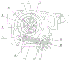
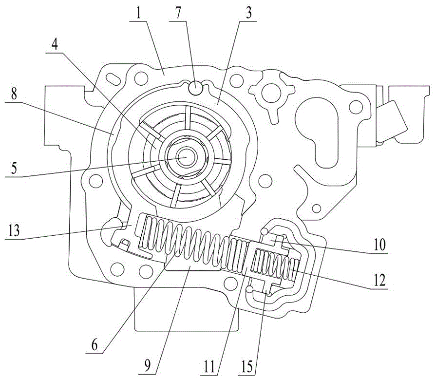
图1为本发明实施例中的泵体内的整体结构示意图;Fig. 1 is the overall structure schematic diagram in the pump body in the embodiment of the present invention;
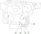
图2为实施例中泵体的结构示意图;Fig. 2 is the structural representation of pump body in the embodiment;
图3为实施例中泵盖的结构示意图;Fig. 3 is the structural representation of pump cover in the embodiment;
图4为实施例中滑阀的结构示意图;Fig. 4 is the structural representation of slide valve in the embodiment;
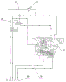
图5为本发明实施例中两级变量机油泵系统处于低油压调节模式时的结构示意图;Fig. 5 is a structural schematic diagram of the two-stage variable oil pump system in the embodiment of the present invention when it is in the low oil pressure adjustment mode;
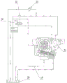
图6为本发明实施例中两级变量机油泵系统处于高油压调节模式时的结构示意图。Fig. 6 is a schematic structural diagram of the two-stage variable oil pump system in the high oil pressure regulation mode in the embodiment of the present invention.
附图标记为:The reference signs are:
1——泵体 2——泵盖 3——滑块1——
4——转子 5——泵轴 6——主变量弹簧4——
7——旋转销 8——反馈腔 9——低压吸油腔7——rotating
10——油压控制腔 11——滑阀 12——副变量弹簧10—Oil
13——滑块臂 14——导向孔 15——导板13——
16——进油孔 17——引油通道 18——弹簧导向槽16——
19——集滤器 20——油底壳 21——泵出口19——
22——机滤器 23——冷启动安全阀 24——开关电磁阀22——
25——排油孔。25——oil drain hole.
具体实施方式Detailed ways
为了便于本领域技术人员的理解,下面结合实施例与附图对本发明作进一步的说明,实施方式提及的内容并非对本发明的限定。In order to facilitate the understanding of those skilled in the art, the present invention will be further described below in conjunction with the embodiments and accompanying drawings, and the contents mentioned in the embodiments are not intended to limit the present invention.
需要提前说明的是,在本发明中,除非另有明确的规定和限定,术语“安装”、“相连”、“连接”、“固定” 等术语应做广义理解,例如,可以是固定连接,也可以是可拆卸连接,或一体地连接。对于本领域的普通技术人员而言,可以根据具体情况理解上述术语在本发明中的具体含义。此外,在本发明中,除非另有明确的规定和限定,第一特征在第二特征“上”或“下”可以包括第一和第二特征直接接触,也可以包括第一和第二特征不是直接接触而是通过它们之间的另外的特征接触。It should be noted in advance that in the present invention, unless otherwise clearly specified and limited, terms such as "installation", "connection", "connection", and "fixation" should be understood in a broad sense, for example, it may be a fixed connection, It can also be detachably connected, or integrally connected. Those of ordinary skill in the art can understand the specific meanings of the above terms in the present invention according to specific situations. In addition, in the present invention, unless otherwise clearly specified and limited, a first feature being "on" or "under" a second feature may include direct contact between the first and second features, or include the first and second features Not in direct contact but through another characteristic contact between them.
如图1-3所示,采用滑阀和开关电磁阀联合控制的两级变量机油泵,包括泵体1、泵盖2、设置在泵体1内的滑块3、转子4、泵轴5以及主变量弹簧6,滑块3的前侧通过旋转销7与泵体1内壁连接,滑块3的左侧面与泵体1内壁之间设有反馈腔8,滑块3的右侧设有低压吸油腔9,反馈腔8与主油道连通,泵体1的右侧设有油压控制腔10,油压控制腔10内设有滑阀11,滑阀11的右端与油压控制腔10的内壁之间抵接有副变量弹簧12,滑块3的后侧设有滑块臂13,主变量弹簧6的左端抵接于滑块臂13、右端伸入油压控制腔10中并抵接于滑阀11,主变量弹簧6和副变量弹簧12的轴向方向一致;油压控制腔10通过开关电磁阀24与主油道连通,从而可在油压控制腔10内产生油压以推动滑阀11往右移动并压缩副变量弹簧12,或者开关电磁阀24可断开油压控制腔10与主油道的连接,从而可使副变量弹簧12推动滑阀11往左移动。As shown in Figure 1-3, the two-stage variable oil pump controlled by the slide valve and the switch solenoid valve includes the
其中,油压控制腔10的左端设有可供滑阀11伸入的导向孔14,滑阀11的外壁轮廓与导向孔14的内壁轮廓相匹配,主变量弹簧6的右端伸入导向孔14中并抵靠于滑阀11的左端面,这使得滑阀11在导向孔14中相当于起到了隔开低压吸油腔9与油压控制腔10的作用,使两个腔内的油压可相对独立,让机油泵的工作更加稳定,作为优选地,导向孔14可设计为圆柱孔的形式,相应地,滑阀11也可设计为外周面为圆柱面形式的结构。Wherein, the left end of the oil
作为优选地,滑阀11的侧壁面上环形设置有导板15,油压控制腔10的内壁上设有限位台阶,导板15可受油压作用往右移动至抵靠于限位台阶,或者导板15可随着副变量弹簧12推动滑阀11往左移动后抵靠于油压控制腔10的左壁面,这使得滑阀11在左右移动的过程中都会受到限位作用,以便于设计副变量弹簧12伸缩到极限位置时,让主变量弹簧6达到所需的与压缩量。Preferably, a
在上述基础上,油压控制腔10的左端设有两个进油孔16,并且两个进油孔16对称设置在滑阀11的两侧,以便于油压控制腔10进油后对滑阀11的推动力更加均匀,让滑阀11的移动更加稳定和顺畅,在实际应用当中,可以使其中一个进油孔16连通开关电磁阀24。然后使两个进油孔16之间连接有引油通道17,以让两个进油孔16都能进油。On the basis of the above, two
作为优选地,如图4所示,滑阀11的右端设有用于供副变量弹簧12伸入的弹簧导向槽18,这样一方面可减轻滑阀11的重量,另一方面可对副变量弹簧12起到导向作用,让副变量弹簧12的运动更加稳定。Preferably, as shown in Figure 4, the right end of the
本领域的技术人员应该知道,作为较优的方案,本实施例中的副变量弹簧12的劲度系数可小于主变量弹簧6。而本实施例中的滑块3、转子4泵轴5的连接方式和常见的可变排量机油泵一样,包括叶片以及定位环的设置,均可参考现有技术,由于本申请的发明点不在于此,因此在本实施例中没有进行和赘述,本领域技术人员对于如何组装这几部分的结构不会存在任何技术障碍。Those skilled in the art should know that, as a better solution, the stiffness coefficient of the secondary
另外,本实施例还提供一种两级变量机油泵系统,其包括上述的采用滑阀和开关电磁阀联合控制的两级变量机油泵,低压吸油腔9通过集滤器19连通油底壳20,泵体1的泵出口21通过机滤器22连接主油道,主油道的油液进入发动机润滑部位后排入油底壳20,主油道通过一条油路连接开关电磁阀24,开关电磁阀24设有A出口和T出口,A出口与油压控制腔10连通,所述T出口与油底壳20连通,开关电磁阀24可控制A出口和T出口其中的一个打开并同时使另一个关闭,油压控制腔10通过排油孔25连通油底壳20,泵出口21还通过一个泄压油路连接油底壳20,泄压油路中设置有冷启动安全阀23。In addition, this embodiment also provides a two-stage variable oil pump system, which includes the above-mentioned two-stage variable oil pump controlled jointly by the slide valve and the switch solenoid valve. The low-pressure
下面详细阐述该系统的工作原理和方式,对于两级可变排量机油泵而言,一般分为低油压调节模式和高油压调节模式进行工作,其中开关电磁阀24可连接车辆自带的控制系统。如图5所示,当进行低油压调节模式时,开关电磁阀24得电,A出口打开且同时T出口关闭,这使得开关电磁阀24连通主油道和油压控制腔10,那么此时主油道的油液可进入到油压控制腔10中形成压力并推动滑阀11往右移动,直至导板15往右抵靠到限位台阶,到达极限位置,使得副变量弹簧12被压缩,相应地,主变量弹簧6伸长并可使其预压缩量处于最小的状态,那么此时主油道直接进入反馈腔8内的油液只需要较小的油压即可推动滑块变量,油液从油底壳20进入低压吸油腔9后进入到滑块3内,在转子、叶片的运动下被压入泵出口21,以高压油的形式进入主油道后送入发动机润滑部位,再最终排入到油底壳20中去。The working principle and method of the system will be described in detail below. For the two-stage variable displacement oil pump, it is generally divided into low oil pressure regulation mode and high oil pressure regulation mode to work, wherein the
如图6所示,当进行高油压调节模式时,开关电磁阀24失电,A出口关闭同时T出口打开,使得主油道的油液无法再进入到油压控制腔10内,那么油压控制腔10内无油压,则此时副变量弹簧12可推动滑阀11往左移动,直到导板12往左抵靠到油压控制腔10的左壁面,到达极限位置,这导致主变量弹簧6被压缩,那么此时相当于需要较大的主油道油压进入反馈腔8内才可克服主变量弹簧6加副变量弹簧12的预压缩力来推动滑块3移动进行变量,这便进入了高油压调节模式,而此时的油压控制腔10内的油液一方面从进油孔16流出至开关电磁阀24再从T出口排入油底壳20,另一方面可通过排油孔25直接排入到油底壳20中。As shown in Figure 6, when the high oil pressure adjustment mode is in operation, the switching
通过上述机油泵及系统实现两级变排量,不仅结构简单,易于实现,而且还使得反馈腔8中只需要接收来自主油道反馈的油液,克服了传统的先导式两级变量机油泵及系统存在的抗干扰能力差的缺点,尤其是温度升高油液粘度降低进而因油液窜漏而产生的干扰,让滑阀11和开关电磁阀24联合控制的模式形成了力矩平衡加力平衡的双组合系统,打破了传统机油泵的结构形式,具备良好的应用前景。Realizing the two-stage variable displacement through the above-mentioned oil pump and system is not only simple in structure and easy to implement, but also makes the
为了让本领域普通技术人员更方便地理解本发明相对于现有技术的改进之处,本发明的一些附图和描述已经被简化,并且上述实施例为本发明较佳的实现方案,除此之外,本发明还可以其它方式实现,在不脱离本技术方案构思的前提下任何显而易见的替换均在本发明的保护范围之内。In order to allow those of ordinary skill in the art to more easily understand the improvement of the present invention compared to the prior art, some drawings and descriptions of the present invention have been simplified, and the above-mentioned embodiments are preferred implementation solutions of the present invention, in addition In addition, the present invention can also be realized in other ways, and any obvious replacements are within the protection scope of the present invention without departing from the concept of the technical solution.
Claims (8)
Priority Applications (1)
| Application Number | Priority Date | Filing Date | Title |
|---|---|---|---|
| CN202111618115.3A CN114215744B (en) | 2021-12-28 | 2021-12-28 | Two-stage variable oil pump and system jointly controlled by slide valve and switch electromagnetic valve |
Applications Claiming Priority (1)
| Application Number | Priority Date | Filing Date | Title |
|---|---|---|---|
| CN202111618115.3A CN114215744B (en) | 2021-12-28 | 2021-12-28 | Two-stage variable oil pump and system jointly controlled by slide valve and switch electromagnetic valve |
Publications (2)
| Publication Number | Publication Date |
|---|---|
| CN114215744A CN114215744A (en) | 2022-03-22 |
| CN114215744B true CN114215744B (en) | 2023-04-07 |
Family
ID=80706292
Family Applications (1)
| Application Number | Title | Priority Date | Filing Date |
|---|---|---|---|
| CN202111618115.3A Active CN114215744B (en) | 2021-12-28 | 2021-12-28 | Two-stage variable oil pump and system jointly controlled by slide valve and switch electromagnetic valve |
Country Status (1)
| Country | Link |
|---|---|
| CN (1) | CN114215744B (en) |
Citations (8)
| Publication number | Priority date | Publication date | Assignee | Title |
|---|---|---|---|---|
| DE102005057339A1 (en) * | 2004-12-18 | 2006-06-22 | Luk Automobiltechnik Gmbh & Co. Kg | Pump e.g. sliding vane pump, for internal combustion engine, has pressure pockets connected/disconnected by check valve that has valve body, where body has three differently arranged functional areas |
| CN101379296A (en) * | 2006-01-31 | 2009-03-04 | 麦格纳动力系有限公司 | Variable displacement variable pressure vane pump system |
| WO2010006705A2 (en) * | 2008-07-15 | 2010-01-21 | Ixetic Bad Homburg Gmbh | Variable displacement pump comprising a flow rate regulator and a pressure valve |
| GB201209338D0 (en) * | 2012-05-25 | 2012-07-11 | Gm Global Tech Operations Inc | Lubrication system for an internal combustion engine |
| JP2014105624A (en) * | 2012-11-27 | 2014-06-09 | Hitachi Automotive Systems Ltd | Variable capacity type pump |
| CN104541059A (en) * | 2012-09-07 | 2015-04-22 | 日立汽车系统株式会社 | Variable-capacity oil pump and oil supply system using same |
| CN105715542A (en) * | 2014-12-18 | 2016-06-29 | 日立汽车系统株式会社 | Variable displacement oil pump |
| CN107605720A (en) * | 2017-10-27 | 2018-01-19 | 湖南机油泵股份有限公司 | A kind of three-level or level Four displacement-variable oil pump based on biswitch magnetic valve |
-
2021
- 2021-12-28 CN CN202111618115.3A patent/CN114215744B/en active Active
Patent Citations (9)
| Publication number | Priority date | Publication date | Assignee | Title |
|---|---|---|---|---|
| DE102005057339A1 (en) * | 2004-12-18 | 2006-06-22 | Luk Automobiltechnik Gmbh & Co. Kg | Pump e.g. sliding vane pump, for internal combustion engine, has pressure pockets connected/disconnected by check valve that has valve body, where body has three differently arranged functional areas |
| CN101379296A (en) * | 2006-01-31 | 2009-03-04 | 麦格纳动力系有限公司 | Variable displacement variable pressure vane pump system |
| WO2010006705A2 (en) * | 2008-07-15 | 2010-01-21 | Ixetic Bad Homburg Gmbh | Variable displacement pump comprising a flow rate regulator and a pressure valve |
| GB201209338D0 (en) * | 2012-05-25 | 2012-07-11 | Gm Global Tech Operations Inc | Lubrication system for an internal combustion engine |
| GB2502369A (en) * | 2012-05-25 | 2013-11-27 | Gm Global Tech Operations Inc | An Engine Lubrication System Flow Control Arrangement Which Includes Piston Oil Jet Cooling and a Variable Output Oil Pump. |
| CN104541059A (en) * | 2012-09-07 | 2015-04-22 | 日立汽车系统株式会社 | Variable-capacity oil pump and oil supply system using same |
| JP2014105624A (en) * | 2012-11-27 | 2014-06-09 | Hitachi Automotive Systems Ltd | Variable capacity type pump |
| CN105715542A (en) * | 2014-12-18 | 2016-06-29 | 日立汽车系统株式会社 | Variable displacement oil pump |
| CN107605720A (en) * | 2017-10-27 | 2018-01-19 | 湖南机油泵股份有限公司 | A kind of three-level or level Four displacement-variable oil pump based on biswitch magnetic valve |
Also Published As
| Publication number | Publication date |
|---|---|
| CN114215744A (en) | 2022-03-22 |
Similar Documents
| Publication | Publication Date | Title |
|---|---|---|
| KR100378704B1 (en) | Compressor and capacity control valve for the compressor and method for controlling capacity of the compressor | |
| JP2908435B1 (en) | Relief valve | |
| CN101379296A (en) | Variable displacement variable pressure vane pump system | |
| CN108894847B (en) | Control system of direct-push type single-cavity supercharging variable-discharge oil pump | |
| JPH04276196A (en) | Screw compressor | |
| JPH0211750B2 (en) | ||
| CN112360589B (en) | Fully variable displacement oil pump with integrated safety valve function slider | |
| CN106051441A (en) | Output displacement variable duplex rotor pump and control system thereof | |
| JP4252178B2 (en) | Relief valve | |
| US8926299B2 (en) | Pump device | |
| CN113565817A (en) | An unloading valve and its loader hydraulic multi-pump confluence system | |
| CN210178435U (en) | A device for a two-stage variable oil pump controlled by a combined valve | |
| CN114215744A (en) | Two-stage variable oil pump and system jointly controlled by slide valve and switch electromagnetic valve | |
| CN218760431U (en) | Axial pressure balancing device | |
| CN101375062B (en) | Screw compressor | |
| CN212272338U (en) | Variable displacement oil pump slide block control mechanism | |
| CN213478418U (en) | Oil pump of vehicle and engine | |
| CN111648836B (en) | A variable displacement oil pump slider control mechanism | |
| CN113606214B (en) | Overflow valve and engineering machinery having the same | |
| JPH0456158B2 (en) | ||
| JP2023136256A (en) | air compressor | |
| JP2777713B2 (en) | Capacity control device for hermetic screw compressor | |
| CN216789843U (en) | Novel wall-mounted oil pump with two-stage oil pumping and displacement regulation | |
| JP2517867Y2 (en) | Vane back pressure control device in gas compressor | |
| CN222436526U (en) | An electro-hydraulic composite power control structure for a hydraulic pump |
Legal Events
| Date | Code | Title | Description |
|---|---|---|---|
| PB01 | Publication | ||
| PB01 | Publication | ||
| SE01 | Entry into force of request for substantive examination | ||
| SE01 | Entry into force of request for substantive examination | ||
| GR01 | Patent grant | ||
| GR01 | Patent grant | ||
| CP03 | Change of name, title or address |
Address after: No.69 Hengyue North Road, Chengguan Town, Hengdong County, Hengyang City, Hunan Province Patentee after: Hunan Meihu Intelligent Manufacturing Co.,Ltd. Country or region after: China Address before: No.69 Hengyue North Road, Chengguan Town, Hengdong County, Hengyang City, Hunan Province Patentee before: Hunan Oil Pump Co.,Ltd. Country or region before: China |
|
| CP03 | Change of name, title or address |