CN114683029B - A hair extension button assembly machine - Google Patents
A hair extension button assembly machine Download PDFInfo
- Publication number
- CN114683029B CN114683029B CN202210388662.5A CN202210388662A CN114683029B CN 114683029 B CN114683029 B CN 114683029B CN 202210388662 A CN202210388662 A CN 202210388662A CN 114683029 B CN114683029 B CN 114683029B
- Authority
- CN
- China
- Prior art keywords
- inner ring
- clamping
- outer ring
- station
- along
- Prior art date
- Legal status (The legal status is an assumption and is not a legal conclusion. Google has not performed a legal analysis and makes no representation as to the accuracy of the status listed.)
- Active
Links
Images


Classifications
-
- B—PERFORMING OPERATIONS; TRANSPORTING
- B23—MACHINE TOOLS; METAL-WORKING NOT OTHERWISE PROVIDED FOR
- B23P—METAL-WORKING NOT OTHERWISE PROVIDED FOR; COMBINED OPERATIONS; UNIVERSAL MACHINE TOOLS
- B23P19/00—Machines for simply fitting together or separating metal parts or objects, or metal and non-metal parts, whether or not involving some deformation; Tools or devices therefor so far as not provided for in other classes
- B23P19/04—Machines for simply fitting together or separating metal parts or objects, or metal and non-metal parts, whether or not involving some deformation; Tools or devices therefor so far as not provided for in other classes for assembling or disassembling parts
-
- A—HUMAN NECESSITIES
- A41—WEARING APPAREL
- A41G—ARTIFICIAL FLOWERS; WIGS; MASKS; FEATHERS
- A41G5/00—Hair pieces, inserts, rolls, pads, or the like; Toupées
- A41G5/004—Hairpieces, e.g. hair extensions
- A41G5/0053—Fastening thereof
- A41G5/0073—Fastening thereof by mechanical fasteners, e.g. clasps, buttons, combs
Landscapes
- Engineering & Computer Science (AREA)
- Mechanical Engineering (AREA)
- Textile Engineering (AREA)
- Automatic Assembly (AREA)
Abstract
Description
技术领域technical field
本发明涉及自动化设备技术领域,具体涉及一种接发扣组装机。The invention relates to the technical field of automation equipment, in particular to a hair extension button assembly machine.
背景技术Background technique
接发是众所周知并且流行的产品,用于增长个人头发的长度或提高蓬松度,同时混合在佩戴者的头发中或与佩戴者的头发结合为一体。接发允许佩戴者通过通常加入多束具有所选的一种或多种长度和一种或多种颜色的接发来修整其头发的外观,以获得期望的外观。Hair extensions are well known and popular products used to increase the length or volume of an individual's hair while being blended into or integrated with the wearer's hair. Hair extensions allow the wearer to modify the appearance of his hair by typically adding strands of hair extensions of one or more lengths and one or more colors of choice to achieve a desired look.
如图1-2所示,为当下流行的一种纳米接发扣,其包括外环100以及设置在外环100内的内环200,内环通常为硅胶材料,硅胶本身具有一定弹性,内环在装入外环后,其通过自身弹性与外环卡紧。接发时,利用钩针将头发穿过内环,由内环夹紧头发固定。As shown in Figure 1-2, it is a kind of nano hair extension button which is popular at present. It includes an
目前,上述接发扣都是通过人工手动组装,即通过人工手动将内环压入外环,但是上述接发扣体积非常小,而且需要用力克服内环的弹性力将内环压入外环,因此在操作时非常不方便,人工组装的工作效率非常低。At present, the above-mentioned hair extension buttons are all manually assembled, that is, the inner ring is manually pressed into the outer ring, but the volume of the above-mentioned hair extension buttons is very small, and it is necessary to overcome the elastic force of the inner ring to press the inner ring into the outer ring , so it is very inconvenient to operate, and the work efficiency of manual assembly is very low.
发明内容Contents of the invention
为了克服背景技术的不足,本发明提供一种接发扣组装机。In order to overcome the disadvantages of the background technology, the present invention provides a hair extension button assembly machine.
本发明所采用的技术方案:一种接发扣组装机,包括:The technical solution adopted in the present invention: a hair extension assembly machine, comprising:
外环输送装置,用于将外环从进料工位输送至组装工位;The outer ring conveying device is used to transport the outer ring from the feeding station to the assembly station;
内环组装装置,用于将内环输送至组装工位,并在组装工位,将内环压入外环形成接发扣。The inner ring assembly device is used to transport the inner ring to the assembly station, and at the assembly station, press the inner ring into the outer ring to form a hair extension button.
所述外环输送装置同时用于将接发扣从组装工位输送至下料工位。The outer ring conveying device is also used to convey the hair extension buttons from the assembly station to the unloading station.
所述外环输送装置包括支撑轨道、外环移送机构以及外环夹持机构;所述支撑轨道沿X轴方向直线布置,并依次通过进料工位、组装工位与下料工位;所述外环移送机构设置在支撑轨道的其中一侧,包括能沿X轴方向直线滑移的滑动座以及驱使滑动座往复滑移的第一驱动件;所述外环夹持机构安装在外环移送机构上,包括能够沿Y轴方向直线滑移的夹持座以及驱使夹持座往复滑移的第二驱动件;所述夹持座朝向支撑轨道的一侧至少形成有一组与外环适配的夹持槽,所述夹持座通过沿Y轴方向的动作实现与外环的夹持与分离,通过沿X轴方向的动作实现外环沿支撑轨道移送。The outer ring conveying device includes a support track, an outer ring transfer mechanism and an outer ring clamping mechanism; the support track is arranged in a straight line along the X-axis direction, and passes through the feeding station, the assembly station and the blanking station in sequence; The outer ring transfer mechanism is arranged on one side of the support track, and includes a sliding seat capable of linearly sliding along the X-axis direction and a first driving member that drives the sliding seat to reciprocate and slide; the outer ring clamping mechanism is installed on the outer ring The transfer mechanism includes a clamping seat capable of linearly sliding along the Y-axis direction and a second driving member that drives the clamping seat to reciprocate and slide; the side of the clamping seat facing the support track forms at least one set of The clamping groove is equipped, and the clamping seat realizes the clamping and separation from the outer ring through the action along the Y axis direction, and realizes the transfer of the outer ring along the support track through the action along the X axis direction.
所述夹持座上设有两组夹持槽,两组夹持槽分别位于夹持座沿X轴方向的两端;且所述进料工位与组装工位之间的间距、组装工位与下料工位之间的间距、以及夹持座上两组夹持槽之间的间距相一致。The clamping seat is provided with two groups of clamping grooves, and the two groups of clamping grooves are respectively located at both ends of the clamping seat along the X-axis direction; and the distance between the feeding station and the assembly station, the assembly process The distance between the position and the blanking station, and the distance between the two groups of clamping grooves on the clamping seat are consistent.
所述内环组装装置包括内环定位导向机构、移动机构、内环夹持机构以及内环组装机构;所述内环定位导向机构安装在组装工位,包括支撑板,所述支撑板上形成有若干上下导通并沿X轴方向并列设置的导向槽;所述移动机构包括移动座以及驱使移动座沿Y轴与Z轴方向动作的移动驱动单元;所述内环夹持机构安装在移动座上,用于夹持内环,能随移动座动作并将内环放入支撑板的导向槽内;所述内环组装机构安装在移动座上,包括若干与支撑板上导向槽相适配的压杆,所述压杆能随移动座动作插入导向槽并将内环沿导向槽向下压装入外环。The inner ring assembly device includes an inner ring positioning guide mechanism, a moving mechanism, an inner ring clamping mechanism and an inner ring assembly mechanism; There are a number of guide grooves that are connected up and down and arranged side by side along the X-axis direction; the moving mechanism includes a moving seat and a moving drive unit that drives the moving seat to move along the Y-axis and Z-axis directions; the inner ring clamping mechanism is installed on the moving On the seat, it is used to clamp the inner ring, which can move with the moving seat and put the inner ring into the guide groove of the supporting plate; the inner ring assembly mechanism is installed on the moving seat, including several guide grooves on the supporting plate The matching pressing rod can be inserted into the guide groove along with the movement of the moving seat and the inner ring can be pressed down along the guiding groove into the outer ring.
所述导向槽包括与内环适配的圆形部以及沿圆形部周向均布的若干凸出部。The guide groove includes a circular portion adapted to the inner ring and several protrusions uniformly distributed along the circumference of the circular portion.
所述内环夹持机构包括限位块、若干夹持杆以及能驱使夹持杆上下往复滑移的第三驱动件;所述夹持杆贯穿限位块并与内环的内圈适配,所述夹持杆通过沿Z轴方向的上下动作实现与内环的夹持与分离。The clamping mechanism of the inner ring includes a limit block, a plurality of clamping rods and a third driving member capable of driving the clamping rod to reciprocate up and down; the clamping rod passes through the limit block and is adapted to the inner ring of the inner ring , the clamping rod realizes clamping and separation from the inner ring by moving up and down along the Z-axis direction.
所述支撑板连接有驱使其上下动作的第四驱动件。The support plate is connected with a fourth driving member that drives it to move up and down.
所述支撑板延伸至下料工位,所述支撑板对应下料工位的位置设有若干下料限位杆,所述下料限位杆外轮廓小于内环内圈。The support plate extends to the blanking station, and the support plate is provided with a number of blanking limit rods corresponding to the blanking station, and the outer contour of the blanking limit rods is smaller than the inner ring of the inner ring.
本发明的有益效果是:采用以上方案,能够实现接发扣的自动组装作业,减少人工操作,降低人工成本低,且提高组装工作效率。The beneficial effects of the present invention are: adopting the above scheme, the automatic assembly operation of the hair extension can be realized, the manual operation is reduced, the labor cost is reduced, and the assembly work efficiency is improved.
附图说明Description of drawings
图1为接发扣的结构示意图。Fig. 1 is a structural schematic diagram of a hair extension button.
图2为接发扣的分解结构示意图。Fig. 2 is a schematic diagram of an exploded structure of a hair extension.
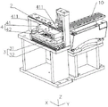
图3为本发明实施例接发扣组装机的结构示意图。Fig. 3 is a structural schematic diagram of a hair extension assembling machine according to an embodiment of the present invention.
图4为本发明实施例接发扣组装机省略部分结构后的结构示意图。Fig. 4 is a structural schematic diagram of the hair extension assembling machine according to the embodiment of the present invention, with some structures omitted.
图5为本发明实施例接发扣组装机省略部分结构后另一角度下的结构示意图。Fig. 5 is a structural schematic view from another angle of the hair extension assembling machine according to the embodiment of the present invention with some structures omitted.
图6为本发明实施例外环输送装置的结构示意图。Fig. 6 is a schematic structural diagram of an outer ring conveying device according to an embodiment of the present invention.
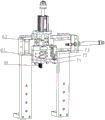
图7为本发明实施例内环组装装置的结构示意图。Fig. 7 is a schematic structural diagram of an inner ring assembly device according to an embodiment of the present invention.
图8为本发明实施例移动机构与内环夹持机构的结构示意图。Fig. 8 is a schematic structural diagram of the moving mechanism and the inner ring clamping mechanism according to the embodiment of the present invention.
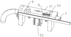
图9为本发明实施例内环定位导向机构的结构示意图。Fig. 9 is a schematic structural view of the positioning and guiding mechanism of the inner ring according to the embodiment of the present invention.
图10为图9中A处的放大示意图。FIG. 10 is an enlarged schematic view of point A in FIG. 9 .
具体实施方式Detailed ways
下面结合附图对本发明实施例作进一步说明。The embodiments of the present invention will be further described below in conjunction with the accompanying drawings.
如图1-2所示,一种接发扣,其包括外环100与内环200,内环200设置在外环100内圈,内环100采用具有一定弹性的硅胶环,本实施例用于接发扣的自动组装,即将内环200压入外环100形成所述的接发扣。As shown in Figure 1-2, a hair extension button includes an
如图3-10所示,一种接发扣组装机,包括机架1与控制装置,以及安装在机架1上的外环进料装置10、内环进料装置11、外环输送装置、内环组装装置。As shown in Figure 3-10, a hair extension assembly machine includes a frame 1 and a control device, and an outer
如图3-6所示,所述外环进料装置10设置在进料工位,用于外环的自动进料,所述外环进料装置10采用常规进料装置,如本实施例中,其采用振动盘的进料形式,由振动盘振动实现自动排序供料,外环能够沿外环进料轨道持续进料,在外环进料轨道的末端还可以进一步设置间歇性动作的外环定位机构,用于阻挡外环,实现外环的间歇性进料,使其能够保持与外环输送装置相同的运动节拍,保证外环稳定的进料作业。其中,所述外环进料轨道设有多条,能够实现多个外环的同步进料,在本实施例中,外环进料轨道设有4条。As shown in Figures 3-6, the outer
如图6所示,所述外环输送装置包括支撑轨道2、外环移送机构3以及外环夹持机构4,用于外环间歇性输送转移。As shown in FIG. 6 , the outer ring conveying device includes a
所述支撑轨道2沿X轴方向直线布置,所述支撑轨道2上形成有宽度与外环适配且深度小于外环长度的轨道槽,外环能够沿支撑轨道2的轨道槽进行输送,所述支撑轨道2沿X轴方向从前往后的依次通过进料工位、组装工位与下料工位。The
所述外环移送机构3设置在支撑轨道2的其中一侧,包括能沿X轴方向直线滑移的滑动座31以及驱使滑动座31往复滑移的第一驱动件32,所述第一驱动件32具体可以采用气缸、油缸、直线电机或电动丝杆等直线驱动件。The outer
所述外环夹持机构4安装在外环移送机构3的滑动座31上,其包括能够沿Y轴方向直线滑移的夹持座41以及驱使夹持座41往复滑移的第二驱动件42,所述第二驱动件42具体可以采用气缸、油缸、直线电机或电动丝杆等直线驱动件。The outer
所述夹持座41朝向支撑轨道2的一侧形成有两组与外环适配的夹持槽411,夹持槽411具体为U型槽,所述夹持座41通过沿Y轴方向的动作实现与外环的夹持与分离,通过沿X轴方向的动作实现外环沿支撑轨道2移送。通过上述外环输送装置能够用于将外环从进料工位输送至组装工位,并将组装完成的接发扣从组装工位输送至下料工位。The side of the
其中,所述夹持座41上设有两组夹持槽411,两组夹持槽411分别位于夹持座沿X轴方向的两端;且所述进料工位与组装工位之间的间距、组装工位与下料工位之间的间距、以及夹持座上两组夹持槽411之间的间距相一致,夹持座41在将进料工位的外环输送至组装工位的同时,能够将组装工位的接发扣成品输送至下料工位进行下料,进一步提高工作效率。Wherein, the
而且,每组夹持槽411均包含有4个夹持槽,与外环进料装置10的外环进料轨道数量相一致,那么在每次输送动作时,均能够同时夹持4个外环,大大提高工作效率,当然,每组夹持槽与外环进料轨道的数量不局限于4个,也可以是3个、5个甚至更多,采用4个时,既满足动作的高效性,提高工作效率,同时又保证整体设备结构紧凑,动作稳定,是一个较为合理的选择。Moreover, each set of
上述外环输送装置具体动作过程如下:The specific action process of the above-mentioned outer ring conveying device is as follows:
1)夹持座41在第二驱动件42的动作下沿Y轴方向朝向支撑轨道2动作,夹持座41前端的一组夹持槽能够卡住被送入到进料工位的外环;1) The
2)夹持座41在外环移送机构3的动作下沿X轴方向从前向后进行输送,将外环送入组装工位,进行组装;2) The clamping
3)夹持座41在第二驱动件42的动作下沿Y轴方向远离支撑轨道2动作,与外环实现分离,然后在外环移送机构3的动作下沿X轴方向从后向前进行复位;3) The clamping
4)复位后,夹持座41在第二驱动件42的动作下再次沿Y轴方向朝向支撑轨道2动作,夹持座41前端的一组夹持槽能够卡住被送入到进料工位新的一组外环,而夹持座41后端的一组夹持槽则能够卡住完成组装的接线扣;4) After reset, the clamping
5)夹持座41在外环移送机构3的动作下沿X轴方向从前向后进行输送,新的一组外环被送入组装工位,进行组装,而完成组装的接线扣则被送入到下料工位进行下料;5) The clamping
6)夹持座41在第二驱动件42的动作下沿Y轴方向远离支撑轨道2动作,与外环、接线扣实现分离,然后在外环移送机构3的动作下沿X轴方向从后向前进行复位;6) The clamping
7)复位后重复动作4-6,便可实现连续的送料动作。7) Repeat action 4-6 after reset to realize continuous feeding action.
如图3-5及图7所示,所述内环进料装置11与外环进料装置10平行设置,采用与外环进料装置10相似的进料装置,由振动盘振动实现内环的自动排序供料,且内环能够沿内环进料轨道持续进料,在内环进料轨道的末端则进一步设置间歇性动作的内环推送机构,用于推出内环,实现内环的间歇性进料,使其能够保持与内环组装装置相同的运动节拍,保证内环稳定的进料作业。其中,所述内环进料轨道同样设置4条,每次进料4个内环。As shown in Figure 3-5 and Figure 7, the inner
如图7-10所示,所述内环组装装置包括内环定位导向机构5、移动机构6、内环夹持机构7以及内环组装机构8。As shown in FIGS. 7-10 , the inner ring assembly device includes an inner ring
所述内环定位导向机构5设置在组装工位,并位于支撑轨道2的上方,所述内环定位导向机构5包括支撑板51,所述支撑板51上形成有若干上下导通并沿X轴方向依次并列的导向槽52,所述导向槽52包括与内环适配的圆形部521以及沿圆形部521外圆对称布置的若干凸出部522。The inner ring
所述移动机构6包括移动座61以及驱使移动座61动作的移动驱动单元62,所述移动驱动单元62包括两组交叉设置的直线驱动单元,其驱动源具体可以气缸、油缸、直线电机或电动丝杆,能够驱使移动座61沿Y轴与Z轴方向动作。The moving
所述内环夹持机构7安装在移动座61上,包括限位块71、若干夹持杆72以及驱使夹持杆72上下往复滑移的第三驱动件73,所述限位块71上形成有上下导通且与夹持杆72适配的导槽,所述夹持杆72贯穿导槽并与内环的内圈适配,所述第三驱动件73具体可以采用气缸、油缸、直线电机或电动丝杆等直线驱动件,所述内环夹持机构7用于夹持内环,夹持杆72通过插入内环实现对内环的夹持,夹持杆72通过沿Z轴方向的上下动作实现与内环的夹持与分离,同时随着移动座61的动作,并将内环放入支撑板51的导向槽52内。The inner
所述内环组装机构8同样安装在移动座61上,包括若干与支撑板51上导向槽52相适配的压杆81,所述压杆81能随移动座61动作插入导向槽52并将内环沿导向槽52向下压装入外环。The inner
当然,压杆81、夹持杆72的数量与每组夹持槽411的数量相同。Of course, the number of
另外,所述支撑板51还连接有驱使其上下动作的第四驱动件53,所述支撑板51同样可以采用气缸、油缸、直线电机或电动丝杆等直线驱动件,在组装动作时,可通过支撑板51压住外环,进一步确保外环位置稳定,保证准确组装动作,同时支撑板51在压住外环时,固定外环,能进一步方便夹持座41与外环分离。In addition, the
进一步的,所述支撑板51延伸至下料工位,所述支撑板51对应下料工位的位置设有若干下料杆9,所述下料杆9的直径略小于内环内圈,在外环输送装置将成品接发扣从组装工位输送至下料工位时,下料限位杆9能够在支撑板51的驱动下同步向下动作,并插入到接发扣的内环内圈,从而能进一步方便夹持座41沿Y轴推出时,能够与外环快速分离。Further, the
上述内环组装装置的具体动作过程如下:The specific action process of the above-mentioned inner ring assembly device is as follows:
1)夹持杆72穿出至限位块71下方,并在移动机构6的动作下,夹持杆72穿过由内环进料装置11送出的一组内环内圈,利用内环本身弹性,使得内环固定套设在夹持杆72端部,完成夹持动作;1) The clamping
2)内环夹持机构7在移动机构6的动作下进行转移,使得其夹持杆72伸入导向槽52,并利用限位块71将内环压入到导向槽52的圆形部内,然后夹持杆72在第三驱动件73的动作下沿Z轴方向向上收缩,利用限位块71将内环从夹持杆72上脱出;2) The inner
3)内环夹持机构7在移动机构6的动作下进行复位转移,夹持杆72重新穿出至限位块71下方,在移动机构6的动作下,夹持杆72穿过新的一组内环内圈,完成夹持,同时压杆81被伸入到导向槽52内,并将导向槽52的内环沿导向槽52向下压入到组装工位的外环内,完成内环组装动作;3) The inner
4)重复动作2-3,实现连续的组装动作。4) Repeat actions 2-3 to achieve continuous assembly actions.
如图3-5所示,在支撑轨道2的末端还设有储料框12,成品接线扣在下料工位下料后,会留在支撑轨道2上,随着外环输送装置的重复动作,夹持座会将接线扣沿支撑轨道2不断向后推送,并将接线扣推到储料框12中进行收集。As shown in Figure 3-5, there is also a
采用以上方案,能够实现接发扣的自动组装作业,减少人工操作,降低人工成本低,且提高组装工作效率。By adopting the above solution, the automatic assembly operation of the hair extension can be realized, the manual operation is reduced, the labor cost is reduced, and the assembly work efficiency is improved.
在本发明的描述中,需要说明的是,术语“中心”、“纵向”、“横向”、“上”、“下”、“前”、“后”、“左”、“右”、“竖直”、“水平”、“顶”、“底”、“内”、“外”等指示的方位或位置关系为基于附图所示的方位或位置关系,仅是为了便于描述本发明和简化描述,而不是指示或暗示所指的装置或元件必须具有特定的方位、以特定的方位构造和操作,因此不能理解为对本发明的限制。此外,术语“第一”、“第二”仅用于描述目的,而不能理解为指示或暗示相对重要性。In the description of the present invention, it should be noted that the terms "center", "longitudinal", "transverse", "upper", "lower", "front", "rear", "left", "right", " The orientations or positional relationships indicated by "vertical", "horizontal", "top", "bottom", "inner" and "outer" are based on the orientations or positional relationships shown in the drawings, and are only for the convenience of describing the present invention and Simplified descriptions, rather than indicating or implying that the device or element referred to must have a particular orientation, be constructed and operate in a particular orientation, and thus should not be construed as limiting the invention. In addition, the terms "first" and "second" are used for descriptive purposes only, and should not be understood as indicating or implying relative importance.
在本发明的描述中,需要说明的是,除非另有明确的规定和限定,术语“安装”、“相连”、“连接”应做广义理解,例如,可以是固定连接,也可以是可拆卸连接,或一体地连接;可以是机械连接,也可以是电连接;可以是直接相连,也可以通过中间媒介间接相连,可以是两个元件内部的连通。对于本领域的普通技术人员而言,可以具体情况理解上述术语在本发明中的具体含义。此外,在本发明的描述中,除非另有说明,“多个”的含义是两个或两个以上。In the description of the present invention, it should be noted that unless otherwise specified and limited, the terms "installation", "connection" and "connection" should be understood in a broad sense, for example, it can be a fixed connection or a detachable connection. Connected, or integrally connected; it can be mechanically connected or electrically connected; it can be directly connected or indirectly connected through an intermediary, and it can be the internal communication of two components. Those of ordinary skill in the art can understand the specific meanings of the above terms in the present invention in specific situations. In addition, in the description of the present invention, unless otherwise specified, "plurality" means two or more.
各位技术人员须知:虽然本发明已按照上述具体实施方式做了描述,但是本发明的发明思想并不仅限于此发明,任何运用本发明思想的改装,都将纳入本专利专利权保护范围内。Notes to all technical personnel: Although the present invention has been described according to the above-mentioned specific embodiments, the inventive idea of the present invention is not limited to this invention, and any modification using the inventive idea will be included in the scope of protection of this patent.
Claims (8)
Priority Applications (1)
| Application Number | Priority Date | Filing Date | Title |
|---|---|---|---|
| CN202210388662.5A CN114683029B (en) | 2022-04-14 | 2022-04-14 | A hair extension button assembly machine |
Applications Claiming Priority (1)
| Application Number | Priority Date | Filing Date | Title |
|---|---|---|---|
| CN202210388662.5A CN114683029B (en) | 2022-04-14 | 2022-04-14 | A hair extension button assembly machine |
Publications (2)
| Publication Number | Publication Date |
|---|---|
| CN114683029A CN114683029A (en) | 2022-07-01 |
| CN114683029B true CN114683029B (en) | 2023-02-10 |
Family
ID=82142303
Family Applications (1)
| Application Number | Title | Priority Date | Filing Date |
|---|---|---|---|
| CN202210388662.5A Active CN114683029B (en) | 2022-04-14 | 2022-04-14 | A hair extension button assembly machine |
Country Status (1)
| Country | Link |
|---|---|
| CN (1) | CN114683029B (en) |
Families Citing this family (1)
| Publication number | Priority date | Publication date | Assignee | Title |
|---|---|---|---|---|
| CN120680733B (en) * | 2025-08-20 | 2025-10-28 | 乐清市宏旭自动化科技有限公司 | Connect knot equipment |
Citations (4)
| Publication number | Priority date | Publication date | Assignee | Title |
|---|---|---|---|---|
| JPH081327A (en) * | 1994-06-15 | 1996-01-09 | Hino Motors Ltd | Working device for ring-shaped work |
| CN210549364U (en) * | 2019-07-19 | 2020-05-19 | 苏州康克莱自动化科技有限公司 | Small-size bearing press fitting equipment |
| CN210756230U (en) * | 2019-06-28 | 2020-06-16 | 无锡双益精密机械有限公司 | Automatic lining ring press-in machine |
| CN213969855U (en) * | 2020-12-31 | 2021-08-17 | 河北亚超轴承集团有限公司 | A interior outer ring suit device for antifriction bearing production |
-
2022
- 2022-04-14 CN CN202210388662.5A patent/CN114683029B/en active Active
Patent Citations (4)
| Publication number | Priority date | Publication date | Assignee | Title |
|---|---|---|---|---|
| JPH081327A (en) * | 1994-06-15 | 1996-01-09 | Hino Motors Ltd | Working device for ring-shaped work |
| CN210756230U (en) * | 2019-06-28 | 2020-06-16 | 无锡双益精密机械有限公司 | Automatic lining ring press-in machine |
| CN210549364U (en) * | 2019-07-19 | 2020-05-19 | 苏州康克莱自动化科技有限公司 | Small-size bearing press fitting equipment |
| CN213969855U (en) * | 2020-12-31 | 2021-08-17 | 河北亚超轴承集团有限公司 | A interior outer ring suit device for antifriction bearing production |
Also Published As
| Publication number | Publication date |
|---|---|
| CN114683029A (en) | 2022-07-01 |
Similar Documents
| Publication | Publication Date | Title |
|---|---|---|
| CN114683029B (en) | A hair extension button assembly machine | |
| CN207972052U (en) | Frame punches production line | |
| CN106820493B (en) | A kind of intelligence punching beading apparatus people | |
| CN210225209U (en) | Automatic series excited motor stator slot-entering paper machine | |
| CN115156903A (en) | Automatic moving cutter set assembling device for automatic razor head assembling line | |
| CN107263071B (en) | Automatic jump ring assembler | |
| CN207563546U (en) | A kind of new and effective pneumatic flag-shaped Linker Mold | |
| CN210394793U (en) | Bead-nailing embroidery machine | |
| CN210054847U (en) | Fancy pulling piece reverse-penetrating head penetrating machine | |
| CN219026568U (en) | Production assembly equipment for coil clamps | |
| CN211208873U (en) | Automatic forming machine for 5G base station antenna radio frequency SMP (symmetric multiple processing) plate-to-plate adapter sleeve | |
| CN207759677U (en) | A kind of pearl embroidery machine send pearl device | |
| CN212822463U (en) | Riveting device and equipment | |
| CN221489234U (en) | Zipper head penetrating device | |
| CN210620974U (en) | Automatic double-station zipper head hanging device | |
| CN212192048U (en) | A light string automatic assembly equipment | |
| CN109348701B (en) | Vibration type tubular flying device | |
| CN217127737U (en) | Small-mouth lengthening type computer sewing machine | |
| CN223879118U (en) | A fabric pressing and feeding device | |
| CN205629795U (en) | Duplex position allies oneself with dynamic positioning device | |
| CN219729740U (en) | Multi-position automatic variable-pitch transfer mechanism | |
| CN223590186U (en) | Press fit device with good press fit effect | |
| CN220946286U (en) | Charging head and tail material feeding and folding equipment | |
| CN223977932U (en) | Cell feeding mechanism and winding equipment | |
| CN219945184U (en) | Big and small piece feeding mechanism of high-speed clip assembly machine |
Legal Events
| Date | Code | Title | Description |
|---|---|---|---|
| PB01 | Publication | ||
| PB01 | Publication | ||
| SE01 | Entry into force of request for substantive examination | ||
| SE01 | Entry into force of request for substantive examination | ||
| GR01 | Patent grant | ||
| GR01 | Patent grant | ||
| PE01 | Entry into force of the registration of the contract for pledge of patent right | ||
| PE01 | Entry into force of the registration of the contract for pledge of patent right |
Denomination of invention: A hair clip assembly machine Granted publication date: 20230210 Pledgee: Qingtian branch of China Postal Savings Bank Limited by Share Ltd. Pledgor: ZHEJIANG HONGRI AUTOMATION TECHNOLOGY Co.,Ltd. Registration number: Y2025980001727 |