Manipulator moving device for machine tool
Technical Field
The invention relates to the technical field of workpiece processing equipment accessories, in particular to the technical field of a manipulator moving device for a machine tool.
Background
Rod barrel machining devices in the market generally achieve the clamping process of the rod barrel machining devices by chucks after being transmitted through rollers and directly reach the chucks of a machine tool through a hollow main shaft of the machine tool, and the rod barrel can be driven by the rollers to exit the machine tool after machining is completed, so that the automatic machining requirements are met; the rod barrel type processing device is mainly used for processing long rod barrels, when short rod barrels are processed by the rod barrel type processing device, the distance between a power roller for supporting and transmitting the rod barrels and the distance between front and rear chucks of a processing machine tool are fixed, the short rod barrels directly fall between the two chucks after entering a hollow main shaft of the machine tool through a roller due to unbalance, the short rod barrels cannot automatically clamp the short rod barrels, the short rod barrels cannot automatically withdraw from the machine tool, and therefore the short rod barrels can only be processed manually.
In order to reduce the labor intensity of workers, reduce the potential safety hazard of production and realize automatic processing of short rod barrels, a manipulator moving device for a machine tool is designed.
Disclosure of Invention
The technical problem to be solved by the invention is as follows: aiming at the defects of the prior art, the manipulator moving device for the machine tool is provided, can directly extend into a processing device, and can clamp one end of a short rod barrel; thereby avoiding the time waste of manual traction and improving the production efficiency.
The invention adopts the following technical scheme for solving the technical problems:
a manipulator moving device for a machine tool, comprising
The clamping device comprises a machine tool base, a clamping part and a supporting plate, wherein one side of the machine tool base is provided with the clamping part, and the other side of the machine tool base is provided with the supporting plate;
a manipulator slide rail portion, one end of which is disposed on the clamping portion and the other end of which is disposed on the support plate;
the support plate structure is connected to the manipulator slide rail part in a sliding mode and provided with a clamping manipulator structure, and the manipulator used for clamping one end of a workpiece is arranged towards the clamping part.
The manipulator moving device for the machine tool is characterized in that the clamping part is of a box body structure, and two sides of the box body structure are respectively provided with the pneumatic chucks.
The manipulator moving device for a machine tool described above, wherein the inclined slide rail portion is provided to the machine tool base, and the inclined slide rail portion is located between the clamping portion and the support plate; the inclined slide rail part is arranged along the length direction of the machine tool base and is connected with an inclined platform in a sliding mode.
The manipulator moving device for the machine tool is characterized in that a slide rail part is arranged on the inclined platform along the inclined direction of the inclined platform, and a processing device is connected to the slide rail part in a sliding manner.
The manipulator moving device for the machine tool is characterized in that a slide rail is arranged on the upper end surface of the manipulator slide rail part along one side of the length of the manipulator slide rail part, and a rack structure is arranged on the upper end surface of the manipulator slide rail part along the other side of the length of the manipulator slide rail part; and a guide rail is arranged on the side surface of the mechanical slide rail part.
The manipulator moving device for the machine tool is characterized in that the supporting plate structure comprises a first supporting plate and a second supporting plate; one end of the manipulator is arranged on the first supporting plate, and the other end of the manipulator is arranged on the second supporting plate; the first supporting plate is provided with a motor, the motor is provided with a gear structure, and the gear structure is matched with the rack.
The manipulator moving device for a machine tool described above, wherein the first pallet and the second pallet each include an L-shaped sliding portion and an inclined connecting portion connected thereto; the right angle of the L-shaped sliding part is right opposite to one edge of the length direction of the upper end surface of the manipulator sliding rail part; a first sliding block part and a second sliding block part are respectively arranged on two sides of the right angle of the L-shaped sliding part; the first sliding block part is matched with the sliding rail, and the second sliding block part is matched with the guide rail; the lower end of the L-shaped sliding part is connected with the inclined connecting part.
The manipulator moving device for the machine tool is characterized in that the inclined connecting part of the first supporting plate is sleeved with one end of the manipulator structure at the hand grip, and the inclined connecting part of the second supporting plate is sleeved with one end of the manipulator structure, which is opposite to the hand grip; the L-shaped sliding part of the first supporting plate is connected with the L-shaped sliding part of the second supporting plate through a connecting rod.
By adopting the technical scheme, compared with the prior art, the invention has the following technical effects:
according to the invention, the support plate structure can slide on the sliding rail part of the manipulator, so that the manipulator structure is moved on the support plate structure, the manipulator structure can move the short rod barrel, and the short rod barrel is prevented from falling on the clamping part.
Drawings
Fig. 1 is an angular perspective view of a robot moving device of a machine tool according to the present invention;
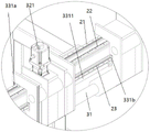
FIG. 2 is an enlarged view of A of FIG. 1;
fig. 3 is a perspective view of another angle of the robot moving device of the machine tool according to the present invention.
1. A machine tool base; 11. a clamping portion; 111. an inclined slide rail portion; 1110. a pneumatic chuck; 12. a support plate; 2. a manipulator slide rail portion; 21. a slide rail; 22. a rack structure; 23. a guide rail; 3. a pallet structure; 31. a manipulator structure; 311. a gripper; 32. a first pallet; 321. a motor; 33. a second pallet; 331. an L-shaped sliding part; 3311. a connecting rod; 331a, a first slider part; 331b, a second slider part; 332. an inclined connecting part; 4. an inclined slide rail portion; 41. a ramp platform; 411. a slide rail portion; 412. provided is a processing device.
Detailed Description
The technical solution of the present invention is further described in detail below with reference to the accompanying drawings.
Fig. 1 is an angular perspective view of a robot moving device of a machine tool according to the present invention; FIG. 2 is an enlarged view of A of FIG. 1; fig. 3 is a perspective view of another angle of the robot moving device of the machine tool according to the present invention.
As shown in fig. 1 to 3, the present embodiment provides a robot moving device for a machine tool, including:
the machine tool base comprises a machine tool base 1, wherein one side of the machine tool base 1 is provided with a clamping part 11, and the other side of the machine tool base 1 is provided with a supporting plate 12.
And one end of the manipulator slide rail part 2 is arranged on the clamping part 11, and the other end of the manipulator slide rail part 2 is arranged on the supporting plate 12.
The layer board structure 3, layer board structure 3 sliding connection is in manipulator slide rail part 2 to layer board structure 3 centre gripping manipulator structure 31, the manipulator for centre gripping work piece one end sets up towards the clamping part.
The above are merely preferred embodiments of the present invention, and the embodiments and the protection scope of the present invention are not limited thereby.
Further, in a preferred embodiment, the holding portion 11 is a box structure, and the respective air chucks 1110 are provided on both sides of the box structure.
Further, in a preferred embodiment, the inclined slide rail portion 4 is provided to the machine tool base 1, and the inclined slide rail portion 4 is located between the clamping portion 11 and the support plate 12; the inclined slide rail part 4 is arranged along the length direction of the machine tool base 1, and the inclined slide rail part 4 is connected with an inclined platform 41 in a sliding mode.
Further, in a preferred embodiment, a slide rail portion 411 is disposed on the inclined platform 41 along the inclined direction thereof, and the slide rail portion 411 is slidably connected with the processing device 412.
Further, in a preferred embodiment, the upper end surface of the robot slide rail portion 2 is provided with a slide rail 21 along one side of the length thereof, and the upper end surface of the robot slide rail portion 2 is provided with a rack structure 22 along the other side of the length thereof; and the side of the mechanical slide part 2 is provided with a guide rail 23.
Further, in a preferred embodiment, the pallet structure 3 comprises a first pallet 32 and a second pallet 33; one end of the manipulator structure 31 is arranged on the first pallet 32, and the other end of the manipulator structure 31 is arranged on the second pallet 33; the first supporting plate 32 is provided with a motor 321, and an output end of the motor 321 is provided with a gear structure (not shown in the figure), and the gear structure is matched with the rack 22.
Further, in a preferred embodiment, the first and second support plates 32 and 33 each include an L-shaped sliding portion 331 and an inclined connecting portion 332 connected thereto; the right angle of the L-shaped sliding part 331 is right opposite to one edge of the length direction of the upper end surface of the manipulator slide rail part 2; a first slider portion 331a and a second slider portion 331b are provided on both surfaces of the L-shaped sliding portion 331 at right angles; the first slider portion 331a is matched with the slide rail 21, and the second slider portion 331b is matched with the guide rail 23; the lower end of the L-shaped sliding portion 331 is connected to the inclined connecting portion 332.
Further, in a preferred embodiment, the inclined connecting portion 332 of the first supporting plate 32 is sleeved with one end of the robot structure 31 at the position of the hand 311, and the inclined connecting portion of the second supporting plate 33 is sleeved with one end of the robot structure 31 opposite to the hand 311; the L-shaped sliding portion 331 of the first support plate 32 is connected to the L-shaped sliding portion 331 of the second support plate 33 by a link 3311.
In addition to the above embodiments, the present invention also has the following methods of use:
when the short barrel enters the gripping part 11, the pallet structure 3 moves towards the gripping part 11 and the pallet structure 3 moves into the gripping part 11 and the robot structure 31 of the pallet structure 3 starts to grab the end of the short barrel facing the robot structure 31; then the supporting plate structure 3 moves in the direction opposite to the clamping part 31, and the short rod barrel moves in the direction until the two ends of the short rod barrel are respectively positioned at the air chucks 1110 at the two sides of the clamping part 11, and the two air chucks 1110 clamp the short rod barrel; at this time, the machining device 412 is moved to a position facing the short barrel, and the inclined surface platform 41 on the inclined slide rail portion 4 is moved to an end of the adjacent short barrel and machined.
While the invention has been described with reference to a preferred embodiment, it will be understood by those skilled in the art that various changes in form and detail may be made therein without departing from the spirit and scope of the invention.