CN115043473A - Weaving sewage treatment ware - Google Patents

Weaving sewage treatment ware Download PDF

Info

Publication number
CN115043473A
CN115043473A CN202210977648.9A CN202210977648A CN115043473A CN 115043473 A CN115043473 A CN 115043473A CN 202210977648 A CN202210977648 A CN 202210977648A CN 115043473 A CN115043473 A CN 115043473A
Authority
CN
China
Prior art keywords
mixing tank
mixing
top plate
liquid storage
piston
Prior art date
Legal status (The legal status is an assumption and is not a legal conclusion. Google has not performed a legal analysis and makes no representation as to the accuracy of the status listed.)
Granted
Application number
CN202210977648.9A
Other languages
Chinese (zh)
Other versions
CN115043473B (en
Inventor
黄涛
任栋梁
王越
Current Assignee (The listed assignees may be inaccurate. Google has not performed a legal analysis and makes no representation or warranty as to the accuracy of the list.)
Shandong Huasheng Innovative Textile Technology Co ltd
Original Assignee
Yangxin Jinfeng Ecological Fiber Co ltd
Priority date (The priority date is an assumption and is not a legal conclusion. Google has not performed a legal analysis and makes no representation as to the accuracy of the date listed.)
Filing date
Publication date
Application filed by Yangxin Jinfeng Ecological Fiber Co ltd filed Critical Yangxin Jinfeng Ecological Fiber Co ltd
Priority to CN202210977648.9A priority Critical patent/CN115043473B/en
Publication of CN115043473A publication Critical patent/CN115043473A/en
Application granted granted Critical
Publication of CN115043473B publication Critical patent/CN115043473B/en
Active legal-status Critical Current
Anticipated expiration legal-status Critical

Links

Images

Classifications

    • C—CHEMISTRY; METALLURGY
    • C02—TREATMENT OF WATER, WASTE WATER, SEWAGE, OR SLUDGE
    • C02F—TREATMENT OF WATER, WASTE WATER, SEWAGE, OR SLUDGE
    • C02F1/00—Treatment of water, waste water, or sewage
    • C02F1/52—Treatment of water, waste water, or sewage by flocculation or precipitation of suspended impurities
    • C02F1/5281—Installations for water purification using chemical agents
    • B—PERFORMING OPERATIONS; TRANSPORTING
    • B01—PHYSICAL OR CHEMICAL PROCESSES OR APPARATUS IN GENERAL
    • B01F—MIXING, e.g. DISSOLVING, EMULSIFYING OR DISPERSING
    • B01F25/00—Flow mixers; Mixers for falling materials, e.g. solid particles
    • B01F25/10—Mixing by creating a vortex flow, e.g. by tangential introduction of flow components
    • C—CHEMISTRY; METALLURGY
    • C02—TREATMENT OF WATER, WASTE WATER, SEWAGE, OR SLUDGE
    • C02F—TREATMENT OF WATER, WASTE WATER, SEWAGE, OR SLUDGE
    • C02F2103/00—Nature of the water, waste water, sewage or sludge to be treated
    • C02F2103/30—Nature of the water, waste water, sewage or sludge to be treated from the textile industry
    • Y—GENERAL TAGGING OF NEW TECHNOLOGICAL DEVELOPMENTS; GENERAL TAGGING OF CROSS-SECTIONAL TECHNOLOGIES SPANNING OVER SEVERAL SECTIONS OF THE IPC; TECHNICAL SUBJECTS COVERED BY FORMER USPC CROSS-REFERENCE ART COLLECTIONS [XRACs] AND DIGESTS
    • Y02—TECHNOLOGIES OR APPLICATIONS FOR MITIGATION OR ADAPTATION AGAINST CLIMATE CHANGE
    • Y02W—CLIMATE CHANGE MITIGATION TECHNOLOGIES RELATED TO WASTEWATER TREATMENT OR WASTE MANAGEMENT
    • Y02W10/00—Technologies for wastewater treatment
    • Y02W10/10—Biological treatment of water, waste water, or sewage

Landscapes

  • Chemical & Material Sciences (AREA)
  • Chemical Kinetics & Catalysis (AREA)
  • General Chemical & Material Sciences (AREA)
  • Life Sciences & Earth Sciences (AREA)
  • Hydrology & Water Resources (AREA)
  • Engineering & Computer Science (AREA)
  • Environmental & Geological Engineering (AREA)
  • Water Supply & Treatment (AREA)
  • Organic Chemistry (AREA)
  • Separation Of Suspended Particles By Flocculating Agents (AREA)

Abstract

The invention relates to the technical field of sewage treatment, and discloses a textile sewage treatment device which comprises a mixing tank, a treating agent feeding mechanism and a mixing mechanism, wherein a discharge port is formed in the bottom of the mixing tank; the mixing mechanism comprises a piston which is in sliding connection with the mixing tank, a top rod is arranged on one side of the piston, which is far away from the mixing tank, a top plate is arranged at one end of the top rod, which is far away from the mixing tank, and a reciprocating pushing assembly for adjusting the height of the top plate is arranged on the side wall of the mixing tank; the treating agent feeding mechanism comprises a liquid storage pipe arranged on the side wall of the mixing tank, the bottom of the liquid storage pipe is connected with the mixing tank through a material guide pipe, and an arc-shaped pipe connected with the end part of the material guide pipe is arranged inside the mixing tank. The invention is suitable for a textile sewage treatment device, and the mixing treatment is not carried out by arranging the stirring rod in the mixing tank, so that floccules can be better precipitated, and the precipitation effect is improved.

Description

Weaving sewage treatment ware
Technical Field
The invention relates to the technical field of sewage treatment, in particular to a textile sewage treatment device.
Background
The textile industry is the industry with the most serious water pollution problem except the industries of steel, paper making and the like, and the textile industry puts the treated water into a water storage tank through precipitation and regulation links and then discharges the water into the nature or recycles the treated water as industrial water.
Weaving sewage is when handling, need add the post reaction of treating agent and form the flocculent precipitate after mixing, then carry out filtration treatment, but some mixing arrangement of current need use the puddler to carry out stirring treatment, and this has led to the flocculent precipitate can be attached to on the puddler, consequently can influence the sediment of flocculent, needs improve it.
Disclosure of Invention
The invention provides a textile sewage treatment device, which solves the problems in the background technology.
In order to achieve the purpose, the invention provides the following technical scheme:
a textile sewage treatment device comprises a mixing tank, a treating agent feeding mechanism and a mixing mechanism, wherein a discharge port is formed in the bottom of the mixing tank;
the mixing mechanism comprises a piston which is in sliding connection with the mixing tank, a top rod is arranged on one side of the piston, which is far away from the mixing tank, a top plate is arranged at one end of the top rod, which is far away from the mixing tank, and a reciprocating pushing assembly for adjusting the height of the top plate is arranged on the side wall of the mixing tank;
the treating agent feeding mechanism comprises a liquid storage pipe arranged on the side wall of the mixing tank, the bottom of the liquid storage pipe is connected with the mixing tank through a material guide pipe, and an arc-shaped pipe connected with the end part of the material guide pipe is arranged inside the mixing tank.
As a preferable technical scheme of the invention, the inner wall of the liquid storage pipe is provided with a retaining ring, a conical plug matched with the retaining ring is arranged inside the liquid storage pipe, and the side wall of the mixing tank is provided with a suspension assembly for adjusting the height of the conical plug.
As a preferable technical scheme of the invention, the suspension assembly comprises a mounting frame fixedly connected with the mixing tank, the mounting frame is rotatably connected with a winding roller, a lifting rope is wound outside the winding roller, and the free end of the lifting rope is connected with the conical plug.
As a preferable technical scheme of the invention, the side edge of the mounting frame is connected with a sliding plate in a sliding manner, the middle part of the sliding plate is provided with a top block matched with the winding roller, and a spring is arranged between the sliding plate and the mixing tank.
As a preferred technical solution of the present invention, the mounting bracket is slidably connected with a wedge-shaped block matched with the sliding plate, and the section of the wedge-shaped block is trapezoidal.
As a preferred technical scheme of the invention, the ejector rod is connected with the top plate in a sliding manner, one end of the ejector rod, which is far away from the piston, is fixedly connected with the adjusting block, the adjusting block is rotatably connected with the bolt, and the bolt is in threaded connection with the top plate.
As a preferred technical scheme, the reciprocating pushing assembly comprises a placing frame arranged on the side wall of the mixing tank, the placing frame is rotatably connected with a rotating head, one end, close to the mixing tank, of the rotating head is fixedly connected with a rotating plate, one end, far away from the rotating head, of the rotating plate is rotatably connected with one end of a supporting rod, and the other end of the supporting rod is rotatably connected with a top plate.
As a preferable technical scheme of the invention, the top plate is fixedly connected with a sliding rod which is in sliding connection with the placing frame.
As a preferred technical scheme of the invention, the rack is provided with a driving motor, an output shaft of the driving motor is fixedly connected with a first bevel gear, the first bevel gear is meshed with a second bevel gear, and the second bevel gear is fixedly connected with a rotating head.
As a preferable technical scheme of the invention, throttle valves are arranged in the discharge opening and the material guide pipe.
The invention has the following advantages:
the invention is suitable for a textile sewage processor, liquid moves between a liquid storage pipe and a mixing tank through the up-and-down movement of a piston, and the spiral water flow can be formed after the liquid enters the mixing tank due to the arc-shaped pipe arranged at the bottom of the mixing tank, so that the sewage and a treating agent can be fully mixed, however, a stirring rod is not arranged in the mixing tank for mixing treatment, so that floccules can be better precipitated, and the precipitation effect is improved.
Drawings
In order to more clearly illustrate the embodiments of the present invention or the technical solutions in the prior art, the drawings used in the description of the embodiments or the prior art will be briefly described below, it is obvious that the drawings in the following description are only some embodiments of the present invention, and for those skilled in the art, other drawings can be obtained according to the drawings without creative efforts.
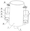
Fig. 1 is a schematic structural diagram of a textile sewage treatment device.
Fig. 2 is a right side view of a textile sewage treatment device.
Fig. 3 is a schematic structural diagram of a reciprocating pushing assembly in the textile sewage treatment device.
Fig. 4 is a schematic structural diagram of an arc-shaped pipe in the textile sewage treatment device.
FIG. 5 is a schematic structural view of a treating agent feeding mechanism in a textile sewage treatment device.
FIG. 6 is a front view of a treating agent feeding mechanism in a textile sewage treatment apparatus.
Fig. 7 is a schematic structural diagram of a suspension assembly in the textile sewage treatment device.
FIG. 8 is a front view of a hanger assembly in a textile sewage processor.
In the figure: 1. a mixing tank; 2. a discharge outlet; 3. a feed inlet; 4. a treating agent feeding mechanism; 5. a mixing mechanism; 6. a piston; 7. a top rod; 8. a top plate; 9. an adjusting block; 10. a reciprocating pushing assembly; 11. a bolt; 12. placing a rack; 13. a drive motor; 14. a first bevel gear; 15. rotating the head; 16. a second bevel gear; 17. a rotating plate; 18. a support bar; 19. a slide bar; 20. a material guide pipe; 21. an arc tube; 22. a liquid storage tube; 23. a retainer ring; 24. a conical plug; 25. a feed inlet; 26. a suspension assembly; 27. a mounting frame; 28. a winding roller; 29. a top block; 30. a sliding plate; 31. a spring; 32. a wedge block; 33. a lifting rope.
Detailed Description
The technical solutions in the embodiments of the present invention will be clearly and completely described below with reference to the drawings in the embodiments of the present invention, and it is obvious that the described embodiments are only a part of the embodiments of the present invention, and not all of the embodiments. All other embodiments, which can be derived by a person skilled in the art from the embodiments given herein without making any creative effort, shall fall within the protection scope of the present invention.
In one embodiment, referring to fig. 1-8, a textile sewage treatment device comprises a mixing tank 1, a discharge port 2 is arranged at the bottom of the mixing tank 1, the mixing tank 1 is a tubular mechanism with an opening at the upper end, flocculent sediments can be discharged through the discharge port 2, a treating agent feeding mechanism 4 and a mixing mechanism 5 are further included;
the mixing mechanism 5 comprises a piston 6 which is in sliding connection with the mixing tank 1, the piston 6 can move up and down along the inside of the mixing tank 1, one side, away from the mixing tank 1, of the piston 6 is provided with an ejector rod 7, one end, away from the mixing tank 1, of the ejector rod 7 is provided with a top plate 8, the side wall of the mixing tank 1 is provided with a reciprocating pushing assembly 10 for adjusting the height of the top plate 8, the reciprocating pushing assembly 10 can push the top plate 8 to move up and down, so that the piston 6 can move up and down along the inside of the mixing tank 1, the front side above the mixing tank 1 is provided with a feed inlet 3, and sewage can be introduced into the mixing tank 1 through the feed inlet 3 for treatment;
treating agent charging mechanism 4, including setting up in the liquid storage pipe 22 of 1 lateral wall of blending tank, liquid storage pipe 22 bottom passes through the passage 20 and connects blending tank 1, the inside of blending tank 1 is equipped with the arc 21 with the passage 20 end connection, and the arc 21 can with the laminating of 1 inner wall of blending tank, and after the quantity more than or equal to two of arc 21, a plurality of arc 21 sets up along fixed direction, carries out the spiral symmetry setting for the center of blending tank 1 for the rivers that the arc 21 flows all are along the clockwise rotation of the inner wall of blending tank 1 or anticlockwise rotation, set up charge door 25 at the top lateral wall of material storage tank, adjust the treating agent through charge door 25.
In one aspect of this embodiment, a retaining ring 23 is disposed on an inner wall of the liquid storage tube 22, a tapered plug 24 engaged with the retaining ring 23 is disposed inside the liquid storage tube 22, the retaining ring 23 is disposed at a lower portion of the liquid storage tube 22, the tapered plug 24 contacts with the retaining ring 23 after moving to the lower portion, so that the liquid storage tube 22 is blocked by the tapered plug 24, a suspension assembly 26 for adjusting the height of the tapered plug 24 is disposed on a side wall of the mixing tank 1, and the suspension assembly 26 can drive the tapered plug 24 to move up and down.
In one aspect of the present embodiment, the suspension assembly 26 includes a mounting bracket 27 fixedly connected to the mixing tank 1, the mounting bracket 27 is rotatably connected to a winding roller 28, a lifting rope 33 is wound around the winding roller 28, a free end of the lifting rope 33 is connected to the tapered plug 24, and the winding roller 28 can pull the tapered plug 24 to move up and down by the lifting rope 33 when rotating. The side edge of the mounting frame 27 is slidably connected with a sliding plate 30, the middle part of the sliding plate 30 is provided with a top block 29 matched with the winding roller 28, a spring 31 is arranged between the sliding plate 30 and the mixing tank 1, and the spring 31 can pull the sliding plate 30 to move towards the direction close to the mixing tank 1. The mounting bracket 27 is slidably connected with a wedge block 32 matched with the sliding plate 30, and the section of the wedge block 32 is trapezoidal. Pushing the wedge block 32 up and down changes the left and right position of the slide plate 30, and when the slide plate 30 moves to a position away from the mixing tank 1, the top block 29 comes into contact with the winding roller 28, so that the winding roller 28 stops moving, and the tapered plug 24 is fixed at a certain height.
In one aspect of the present embodiment, the top rod 7 is slidably connected to the top plate 8, an end of the top rod 7 away from the piston 6 is fixedly connected to the adjusting block 9, the adjusting block 9 is rotatably connected to the bolt 11, and the bolt 11 is threadedly connected to the top plate 8. The distance between the adjusting block 9 and the top plate 8 is changed through the bolt 11, when the interior of the mixing tank 1 needs to be cleaned or sewage is added, an operator can push the top plate 8 to move upwards in a mode of manually rotating the bolt 11, so that the piston 6 can be separated from the mixing tank 1 after moving to the upper side, and the interior of the mixing tank 1 can be cleaned or sewage can be added.
In one aspect of the present embodiment, the reciprocating pushing assembly 10 includes a placing frame 12 disposed on the side wall of the mixing tank 1, the placing frame 12 is rotatably connected to a rotating head 15, one end of the rotating head 15 close to the mixing tank 1 is fixedly connected to a rotating plate 17, one end of the rotating plate 17 far away from the rotating head 15 is rotatably connected to one end of a supporting rod 18, and the other end of the supporting rod 18 is rotatably connected to the top plate 8. Rack 12 is L type structure, and rack 12 sets up lateral wall middle part behind blending tank 1, and swivel head 15 is connected in the top commentaries on classics of rack 12, can reciprocate through bracing piece 18 pulling roof 8 when rotor plate 17 is rotatory. The top plate 8 is fixedly connected with a sliding rod 19 which is connected with the placing rack 12 in a sliding manner. The lower part of the placing rack 12 is connected with the middle part of the sliding rod 19 in a sliding way, and the upper end of the sliding rod 19 is fixedly connected with the top plate 8, so that the limiting effect of the top plate 8 can be achieved through the sliding rod 19. The rack 12 is provided with a driving motor 13, an output shaft of the driving motor 13 is fixedly connected with a first bevel gear 14, the first bevel gear 14 is meshed with a second bevel gear 16, and the second bevel gear 16 is fixedly connected with a rotating head 15.
In one case of this embodiment, a throttle valve is provided in each of the discharge opening 2 and the guide duct 20. The throttle valve can be used for realizing the on-off of the discharge opening 2 and the material guide pipe 20, thereby realizing different discharge modes.
In the implementation process of the embodiment, the throttle valves of the material guiding pipe 20 and the material discharging opening 2 are firstly closed, and the driving motor 13 is started, the output shaft of the driving motor 13 drives the top plate 8 to move upwards through the first bevel gear 14 and the second bevel gear 16 which are meshed and connected, so that the piston 6 moves to the uppermost part of the mixing tank 1, the piston 6 is made to be higher than the mixing tank 1 through the bolt 11, so that the upper opening of the mixing tank 1 is opened, sewage is added into the mixing tank 1 through the material inlet 3, the piston 6 can move downwards through the bolt 11 after the addition is completed, so that the piston 6 moves to the inside of the mixing tank 1, at this time, the winding roller 28 can be manually rotated, the winding roller 28 drives the tapered plug 24 to move upwards through the lifting rope 33, so that the tapered plug 24 is higher than the material charging opening 25 of the liquid storage tank, and because the outer diameter of the tapered plug 24 is smaller than the inner diameter of the liquid storage pipe plug 22, different treating agents can be added into different liquid storing pipes 22 through the feed opening 25, and after the addition is completed, the lifting rope 33 can be released, so that the tapered plug 24 can fall above the treating agents, and the tapered plug 24 floats on the treating agents due to the small specific gravity of the tapered plug 24.
The throttle valve of the guide pipe 20 is opened, at this time, the driving motor 13 is started again, so that the piston 6 moves up and down, the piston 6 moves down first, the sewage in the mixing tank 1 flows into the liquid storage pipe 22 through the guide pipe 20, when the piston 6 moves to the bottom of the mixing tank 1, the air above the mixing tank 1 also enters the liquid storage pipe 22, so as to be discharged through the gap between the liquid storage pipe 22 and the tapered plug 24, when the piston 6 moves up, the liquid in the liquid storage pipe 22 enters the mixing tank 1, and when the liquid enters the mixing tank 1 due to the presence of the arc-shaped pipe 21, the entering liquid forms a spiral water flow at the bottom of the mixing tank 1, so that the mixing treatment of the treating agent and the sewage is realized through the spiral water flow, and when the water flow in the liquid storage pipe 22 flows out, the tapered plug 24 contacts with the retaining ring 23, at this time, the liquid storage pipe 22 is blocked, however, the piston 6 is continuously moved upward at this time, so that the pressure inside the mixing tank 1 is lowered, thereby improving the mixing effect, and thus the mixing treatment of the sewage and the treatment agent is achieved along with the up-and-down movement of the piston 6, after the mixing is completed, the throttle valve in the guide duct 20 may be closed, the sewage in the mixing tank 1 forms flocculent precipitate under the action of the treatment agent, the throttle valve of the discharge port 2 may be opened after the precipitation for a period of time, thereby allowing the flocculent precipitate to be discharged through the bottom of the mixing tank 1, and after the flocculent precipitate is discharged, a receiving device may be provided below the discharge port 2, thereby allowing the treated sewage to be separately discharged from the flocculent precipitate.
The invention is suitable for a textile sewage treatment device, liquid moves between a liquid storage pipe 22 and a mixing tank 1 through the up-and-down movement of a piston 6, and because the arc-shaped pipe 21 is arranged at the bottom of the mixing tank 1, the liquid can form spiral water flow after entering the mixing tank 1, so that sewage and a treatment agent can be fully mixed, but a stirring rod is not arranged in the mixing tank 1 for mixing treatment, so that floccules can be better precipitated, and the precipitation effect is improved.
It will be evident to those skilled in the art that the invention is not limited to the details of the foregoing illustrative embodiments, and that the present invention may be embodied in other specific forms without departing from the spirit or essential attributes thereof. The present embodiments are therefore to be considered in all respects as illustrative and not restrictive, the scope of the invention being indicated by the appended claims rather than by the foregoing description, and all changes which come within the meaning and range of equivalency of the claims are therefore intended to be embraced therein. Any reference sign in a claim should not be construed as limiting the claim concerned.

Claims (10)

1. A textile sewage treatment device comprises a mixing tank, wherein the bottom of the mixing tank is provided with a discharge hole, and is characterized by also comprising a treating agent feeding mechanism and a mixing mechanism;
the mixing mechanism comprises a piston which is in sliding connection with the mixing tank, a top rod is arranged on one side of the piston, which is far away from the mixing tank, a top plate is arranged at one end of the top rod, which is far away from the mixing tank, and a reciprocating pushing assembly for adjusting the height of the top plate is arranged on the side wall of the mixing tank;
the treating agent feeding mechanism comprises a liquid storage pipe arranged on the side wall of the mixing tank, the bottom of the liquid storage pipe is connected with the mixing tank through a material guide pipe, and an arc-shaped pipe connected with the end part of the material guide pipe is arranged inside the mixing tank.
2. A treatment device for textile sewage according to claim 1, wherein the inner wall of the liquid storage pipe is provided with a retaining ring, a conical plug matched with the retaining ring is arranged inside the liquid storage pipe, and the side wall of the mixing tank is provided with a suspension assembly for adjusting the height of the conical plug.
3. The textile sewage processor of claim 2, wherein the suspension assembly comprises a mounting frame fixedly connected with the mixing tank, the mounting frame is rotatably connected with the winding roller, a lifting rope is wound outside the winding roller, and the free end of the lifting rope is connected with the conical plug.
4. A treatment device for textile sewage according to claim 3, wherein the side edges of the mounting frame are slidably connected with sliding plates, the middle parts of the sliding plates are provided with top blocks matched with the winding rollers, and springs are arranged between the sliding plates and the mixing tank.
5. A treatment plant as claimed in claim 4, wherein the mounting frame is slidably connected to a wedge cooperating with the slide plate, the wedge having a trapezoidal cross-section.
6. The textile sewage processor of claim 1, wherein the ejector rod is slidably connected with the top plate, one end of the ejector rod, which is far away from the piston, is fixedly connected with an adjusting block, the adjusting block is rotatably connected with a bolt, and the bolt is in threaded connection with the top plate.
7. The textile sewage processor of claim 1, wherein the reciprocating pushing assembly comprises a placing frame arranged on the side wall of the mixing tank, the placing frame is rotatably connected with a rotating head, one end of the rotating head, which is close to the mixing tank, is fixedly connected with a rotating plate, one end of the rotating plate, which is far away from the rotating head, is rotatably connected with one end of a supporting rod, and the other end of the supporting rod is rotatably connected with a top plate.
8. A treatment device for textile sewage according to claim 7, wherein the top plate is fixedly connected with a sliding rod which is slidably connected with the placing frame.
9. The textile sewage processor of claim 7, wherein the rack is provided with a driving motor, an output shaft of the driving motor is fixedly connected with a first bevel gear, the first bevel gear is meshed with a second bevel gear, and the second bevel gear is fixedly connected with the rotating head.
10. A treatment apparatus for textile wastewater according to claim 1, wherein the discharge port and the material guiding pipe are provided with throttle valves.
CN202210977648.9A 2022-08-16 2022-08-16 Weaving sewage treatment ware Active CN115043473B (en)

Priority Applications (1)

Application Number Priority Date Filing Date Title
CN202210977648.9A CN115043473B (en) 2022-08-16 2022-08-16 Weaving sewage treatment ware

Applications Claiming Priority (1)

Application Number Priority Date Filing Date Title
CN202210977648.9A CN115043473B (en) 2022-08-16 2022-08-16 Weaving sewage treatment ware

Publications (2)

Publication Number Publication Date
CN115043473A true CN115043473A (en) 2022-09-13
CN115043473B CN115043473B (en) 2022-11-15

Family

ID=83167869

Family Applications (1)

Application Number Title Priority Date Filing Date
CN202210977648.9A Active CN115043473B (en) 2022-08-16 2022-08-16 Weaving sewage treatment ware

Country Status (1)

Country Link
CN (1) CN115043473B (en)

Cited By (3)

* Cited by examiner, † Cited by third party
Publication number Priority date Publication date Assignee Title
CN116375184A (en) * 2023-05-26 2023-07-04 日照城投环境科技集团有限公司 Sulfur self-oxygen sewage treatment mechanism
CN120061080A (en) * 2025-04-28 2025-05-30 天津工业大学 Dark-colored animal plush fiber decoloring agent mixing equipment and low-carbon decoloring method
CN120553786A (en) * 2025-07-24 2025-08-29 河北慧纤新材料科技有限公司 A textile wastewater treatment device and treatment process

Citations (17)

* Cited by examiner, † Cited by third party
Publication number Priority date Publication date Assignee Title
US6109778A (en) * 1997-09-22 2000-08-29 United States Filter Corporation Apparatus for homogeneous mixing of a solution with tangential jet outlets
CN106000147A (en) * 2016-07-11 2016-10-12 北京创世捷能机器人有限公司 Mortar mixing and stirring device
US20160354129A1 (en) * 2015-06-03 2016-12-08 Heraeus Medical Gmbh Device for mixing and storing polymethylmethacrylate bone cement
CN207822822U (en) * 2017-10-31 2018-09-07 河北绿色农华作物科技有限公司 A kind of suspension liquid fertilizer refinement mixing arrangement
CN208218479U (en) * 2018-04-11 2018-12-11 浙江君泰生态环保科技有限公司 A kind of flocculant for sewage treatment deployment device
CN109092185A (en) * 2018-08-15 2018-12-28 杜鑫 A kind of impingement mix formula coating material agitator
CN208809067U (en) * 2018-07-03 2019-05-03 王海燕 A kind of pharmacy dispensation apparatus
CN111068536A (en) * 2019-12-12 2020-04-28 陕西航天机电环境工程设计院有限责任公司 Pipeline mixer
CN213132695U (en) * 2020-09-02 2021-05-07 青岛阿兰贝尔科技发展有限公司 Raw material dispersing device for water-based paint
CN213791355U (en) * 2020-11-11 2021-07-27 肇庆苗和堂医药有限公司 A kind of anti-hair loss hair growth water mixing device
CN213834861U (en) * 2020-12-11 2021-07-30 江西高信前沿科技有限公司 Wastewater treatment equipment for chemical production
CN113354144A (en) * 2021-06-04 2021-09-07 重庆智伦电镀有限公司 Nickel-containing wastewater treatment system for industrial park
CN113600055A (en) * 2021-09-02 2021-11-05 河北科技大学 A synthetic device for the production of heat-expandable foamed microspheres
CN214765245U (en) * 2021-05-12 2021-11-19 清远市美佳乐环保新材股份有限公司 Mixed emulsification device is used in synthetic leather penetrant production
CN215627325U (en) * 2021-10-14 2022-01-25 江苏钦越环保科技有限公司 Sewage pressure drive regulation's sewage equalizing basin
CN215963165U (en) * 2021-09-23 2022-03-08 佛山市英霸润滑油有限公司 A blending tank for lubricating oil processing
CN216998121U (en) * 2021-12-21 2022-07-19 常州市深水江边污水处理有限公司 Multi-point dosing device

Patent Citations (17)

* Cited by examiner, † Cited by third party
Publication number Priority date Publication date Assignee Title
US6109778A (en) * 1997-09-22 2000-08-29 United States Filter Corporation Apparatus for homogeneous mixing of a solution with tangential jet outlets
US20160354129A1 (en) * 2015-06-03 2016-12-08 Heraeus Medical Gmbh Device for mixing and storing polymethylmethacrylate bone cement
CN106000147A (en) * 2016-07-11 2016-10-12 北京创世捷能机器人有限公司 Mortar mixing and stirring device
CN207822822U (en) * 2017-10-31 2018-09-07 河北绿色农华作物科技有限公司 A kind of suspension liquid fertilizer refinement mixing arrangement
CN208218479U (en) * 2018-04-11 2018-12-11 浙江君泰生态环保科技有限公司 A kind of flocculant for sewage treatment deployment device
CN208809067U (en) * 2018-07-03 2019-05-03 王海燕 A kind of pharmacy dispensation apparatus
CN109092185A (en) * 2018-08-15 2018-12-28 杜鑫 A kind of impingement mix formula coating material agitator
CN111068536A (en) * 2019-12-12 2020-04-28 陕西航天机电环境工程设计院有限责任公司 Pipeline mixer
CN213132695U (en) * 2020-09-02 2021-05-07 青岛阿兰贝尔科技发展有限公司 Raw material dispersing device for water-based paint
CN213791355U (en) * 2020-11-11 2021-07-27 肇庆苗和堂医药有限公司 A kind of anti-hair loss hair growth water mixing device
CN213834861U (en) * 2020-12-11 2021-07-30 江西高信前沿科技有限公司 Wastewater treatment equipment for chemical production
CN214765245U (en) * 2021-05-12 2021-11-19 清远市美佳乐环保新材股份有限公司 Mixed emulsification device is used in synthetic leather penetrant production
CN113354144A (en) * 2021-06-04 2021-09-07 重庆智伦电镀有限公司 Nickel-containing wastewater treatment system for industrial park
CN113600055A (en) * 2021-09-02 2021-11-05 河北科技大学 A synthetic device for the production of heat-expandable foamed microspheres
CN215963165U (en) * 2021-09-23 2022-03-08 佛山市英霸润滑油有限公司 A blending tank for lubricating oil processing
CN215627325U (en) * 2021-10-14 2022-01-25 江苏钦越环保科技有限公司 Sewage pressure drive regulation's sewage equalizing basin
CN216998121U (en) * 2021-12-21 2022-07-19 常州市深水江边污水处理有限公司 Multi-point dosing device

Cited By (6)

* Cited by examiner, † Cited by third party
Publication number Priority date Publication date Assignee Title
CN116375184A (en) * 2023-05-26 2023-07-04 日照城投环境科技集团有限公司 Sulfur self-oxygen sewage treatment mechanism
CN116375184B (en) * 2023-05-26 2025-07-04 日照城投环境科技集团有限公司 Sulfur autotrophic sewage treatment mechanism
CN120061080A (en) * 2025-04-28 2025-05-30 天津工业大学 Dark-colored animal plush fiber decoloring agent mixing equipment and low-carbon decoloring method
CN120061080B (en) * 2025-04-28 2025-08-22 天津工业大学 Dark animal hair fiber decolorant mixing device and low-carbon decolorization method
JP7820750B1 (en) * 2025-04-28 2026-02-26 天津工業大学 Mixing device for bleaching agent for dark-colored animal hair and villi and low-carbon bleaching method
CN120553786A (en) * 2025-07-24 2025-08-29 河北慧纤新材料科技有限公司 A textile wastewater treatment device and treatment process

Also Published As

Publication number Publication date
CN115043473B (en) 2022-11-15

Similar Documents

Publication Publication Date Title
CN115043473B (en) Weaving sewage treatment ware
CN120058159B (en) Environment-friendly fabric printing and dyeing wastewater treatment system and method
CN218740760U (en) Wastewater sedimentation treatment device
CN116874075B (en) Electric desalting wastewater treatment device
CN210825774U (en) Sewage air-flotation treatment device
CN113105005A (en) Air flotation coagulation integrated advanced treatment equipment for textile sewage
CN107619157A (en) Portable integrated equipment for sewage treatment
CN112759079A (en) Three-dimensional integrated sewage treatment process system
CN112062336A (en) Desulfurization waste water zero release processing system
CN118812105A (en) Sewage treatment equipment and treatment method
CN118811982A (en) Fluorite beneficiation wastewater treatment and recycling device
CN217549080U (en) Black titanium liquid subsides purifier
CN207153182U (en) A kind of three-level sedimentation basin
CN213728514U (en) Waste incineration fly ash treatment device
CN114835331B (en) Energy-saving environment-friendly building wastewater treatment device
CN114380411B (en) Industrial wastewater's purification treatment equipment that becomes more meticulous
CN116871241A (en) Barium chloride raw material ore washing device
CN109305734B (en) Blue algae bloom emergency treatment device and blue algae bloom emergency treatment method
CN203411429U (en) Reactor for removing iron and impurities through continuous settlement of fluid
CN108211450B (en) Sewage filtering treatment device
CN113860580A (en) A marine facility domestic sewage treatment device
CN223324092U (en) Chemical liquid material sedimentation tank
CN109351038B (en) Environment-friendly solid-liquid separation equipment for chemical industry
CN220609449U (en) Vertical integrated sewage treatment plant of intelligence
CN113209687A (en) Waste liquid and waste residue separating device

Legal Events

Date Code Title Description
PB01 Publication
PB01 Publication
SE01 Entry into force of request for substantive examination
TA01 Transfer of patent application right

Effective date of registration: 20221027

Address after: 251900 Xinghu 5th Road, Economic Development Zone, Wudi County, Binzhou City, Shandong Province

Applicant after: Shandong Huasheng innovative Textile Technology Co.,Ltd.

Address before: 251800 north of Gongye 1st Road, Yangxin Economic Development Zone, Binzhou City, Shandong Province (in the courtyard of norui fabric company)

Applicant before: YANGXIN JINFENG ECOLOGICAL FIBER Co.,Ltd.

TA01 Transfer of patent application right
GR01 Patent grant
GR01 Patent grant
PE01 Entry into force of the registration of the contract for pledge of patent right

Denomination of invention: A textile wastewater treatment device

Granted publication date: 20221115

Pledgee: Agricultural Bank of China Limited Wudi County sub branch

Pledgor: Shandong Huasheng innovative Textile Technology Co.,Ltd.

Registration number: Y2024980001276

PE01 Entry into force of the registration of the contract for pledge of patent right