Disclosure of Invention
The invention provides a textile sewage treatment device, which solves the problems in the background technology.
In order to achieve the purpose, the invention provides the following technical scheme:
a textile sewage treatment device comprises a mixing tank, a treating agent feeding mechanism and a mixing mechanism, wherein a discharge port is formed in the bottom of the mixing tank;
the mixing mechanism comprises a piston which is in sliding connection with the mixing tank, a push rod is arranged on one side of the piston away from the mixing tank, a top plate is arranged at one end of the push rod away from the mixing tank, and a reciprocating pushing assembly for adjusting the height of the top plate is arranged on the side wall of the mixing tank;
the treating agent feeding mechanism comprises a liquid storage pipe arranged on the side wall of the mixing tank, the bottom of the liquid storage pipe is connected with the mixing tank through a material guide pipe, and an arc-shaped pipe connected with the end part of the material guide pipe is arranged inside the mixing tank.
As a preferable technical scheme of the invention, the inner wall of the liquid storage pipe is provided with a retaining ring, a conical plug matched with the retaining ring is arranged inside the liquid storage pipe, and the side wall of the mixing tank is provided with a suspension assembly for adjusting the height of the conical plug.
As a preferable technical scheme of the invention, the suspension assembly comprises a mounting frame fixedly connected with the mixing tank, the mounting frame is rotatably connected with a winding roller, a lifting rope is wound outside the winding roller, and the free end of the lifting rope is connected with the conical plug.
As a preferable technical scheme of the invention, the side edge of the mounting frame is connected with a sliding plate in a sliding mode, the middle of the sliding plate is provided with a top block matched with the winding roller, and a spring is arranged between the sliding plate and the mixing tank.
As a preferred technical solution of the present invention, the mounting bracket is slidably connected with a wedge-shaped block matched with the sliding plate, and the section of the wedge-shaped block is trapezoidal.
As a preferred technical scheme of the invention, the ejector rod is connected with the top plate in a sliding manner, one end of the ejector rod, which is far away from the piston, is fixedly connected with the adjusting block, the adjusting block is rotatably connected with the bolt, and the bolt is in threaded connection with the top plate.
As a preferred technical scheme of the invention, the reciprocating pushing assembly comprises a placing frame arranged on the side wall of the mixing tank, the placing frame is rotatably connected with a rotating head, one end of the rotating head, which is close to the mixing tank, is fixedly connected with a rotating plate, one end of the rotating plate, which is far away from the rotating head, is rotatably connected with one end of a supporting rod, and the other end of the supporting rod is rotatably connected with a top plate.
As a preferable technical scheme of the invention, the top plate is fixedly connected with a sliding rod which is connected with the placing frame in a sliding manner.
As a preferred technical scheme of the invention, the rack is provided with a driving motor, an output shaft of the driving motor is fixedly connected with a first bevel gear, the first bevel gear is meshed with a second bevel gear, and the second bevel gear is fixedly connected with a rotating head.
As a preferable technical scheme of the invention, the discharge opening and the material guide pipe are respectively provided with a throttle valve.
The invention has the following advantages:
the invention is suitable for a textile sewage processor, liquid moves between a liquid storage pipe and a mixing tank through the up-and-down movement of a piston, and the spiral water flow can be formed after the liquid enters the mixing tank due to the arc-shaped pipe arranged at the bottom of the mixing tank, so that the sewage and a treating agent can be fully mixed, however, a stirring rod is not arranged in the mixing tank for mixing treatment, so that floccules can be better precipitated, and the precipitation effect is improved.
Detailed Description
The technical solutions in the embodiments of the present invention will be clearly and completely described below with reference to the drawings in the embodiments of the present invention, and it is obvious that the described embodiments are only a part of the embodiments of the present invention, and not all of the embodiments. All other embodiments, which can be derived by a person skilled in the art from the embodiments given herein without making any creative effort, shall fall within the protection scope of the present invention.
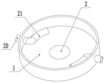
In one embodiment, referring to fig. 1-8, a textile sewage treatment device comprises a mixing tank 1, a discharge port 2 is arranged at the bottom of the mixing tank 1, the mixing tank 1 is a tubular mechanism with an opening at the upper end, flocculent sediments can be discharged through the discharge port 2, a treating agent feeding mechanism 4 and a mixing mechanism 5 are further included;
the mixing mechanism 5 comprises a piston 6 which is in sliding connection with the mixing tank 1, the piston 6 can move up and down along the inside of the mixing tank 1, one side, away from the mixing tank 1, of the piston 6 is provided with an ejector rod 7, one end, away from the mixing tank 1, of the ejector rod 7 is provided with a top plate 8, the side wall of the mixing tank 1 is provided with a reciprocating pushing assembly 10 for adjusting the height of the top plate 8, the reciprocating pushing assembly 10 can push the top plate 8 to move up and down, so that the piston 6 can move up and down along the inside of the mixing tank 1, a feed port 3 is formed in the front side above the mixing tank 1, and sewage can be introduced through the feed port 3 for treatment;
treating agent charging mechanism 4, including setting up in the liquid storage pipe 22 of 1 lateral wall of blending tank, liquid storage pipe 22 bottom passes through the passage 20 and connects blending tank 1, the inside of blending tank 1 is equipped with the arc 21 with the passage 20 end connection, and the arc 21 can with the laminating of 1 inner wall of blending tank, and after the quantity more than or equal to two of arc 21, a plurality of arc 21 sets up along fixed direction, carries out the spiral symmetry setting for the center of blending tank 1 for the rivers that the arc 21 flows all are along the clockwise rotation of the inner wall of blending tank 1 or anticlockwise rotation, set up charge door 25 at the top lateral wall of material storage tank, adjust the treating agent through charge door 25.
In one aspect of this embodiment, a retaining ring 23 is disposed on an inner wall of the liquid storage tube 22, a tapered plug 24 engaged with the retaining ring 23 is disposed inside the liquid storage tube 22, the retaining ring 23 is disposed at a lower portion of the liquid storage tube 22, the tapered plug 24 contacts with the retaining ring 23 after moving to the lower portion, so that the liquid storage tube 22 is blocked by the tapered plug 24, a suspension assembly 26 for adjusting the height of the tapered plug 24 is disposed on a side wall of the mixing tank 1, and the suspension assembly 26 can drive the tapered plug 24 to move up and down.
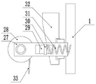
In one aspect of the present embodiment, the suspension assembly 26 includes a mounting bracket 27 fixedly connected to the mixing tank 1, the mounting bracket 27 is rotatably connected to a winding roller 28, a lifting rope 33 is wound around the winding roller 28, a free end of the lifting rope 33 is connected to the tapered plug 24, and the winding roller 28 can pull the tapered plug 24 to move up and down by the lifting rope 33 when rotating. The side edge of the mounting frame 27 is slidably connected with a sliding plate 30, the middle part of the sliding plate 30 is provided with a top block 29 matched with the winding roller 28, a spring 31 is arranged between the sliding plate 30 and the mixing tank 1, and the spring 31 can pull the sliding plate 30 to move towards the direction close to the mixing tank 1. The mounting bracket 27 is slidably connected with a wedge block 32 matched with the sliding plate 30, and the section of the wedge block 32 is trapezoidal. Pushing the wedge block 32 up and down changes the left and right position of the slide plate 30, and when the slide plate 30 moves to a position away from the mixing tank 1, the top block 29 comes into contact with the winding roller 28, so that the winding roller 28 stops moving, and the tapered plug 24 is fixed at a certain height.
In one case of the embodiment, the top rod 7 is slidably connected with the top plate 8, one end of the top rod 7, which is far away from the piston 6, is fixedly connected with the adjusting block 9, the adjusting block 9 rotates the connecting bolt 11, and the bolt 11 is in threaded connection with the top plate 8. Change the interval between regulating block 9 and the roof 8 through bolt 11, when needs clear up or the sewage is reinforced to the inside of blending tank 1, operating personnel can push roof 8 rebound through the mode of manual rotatory bolt 11 to make piston 6 remove the top after can throw off with blending tank 1, can clear up the inside of blending tank 1 this moment and handle or add sewage.
In one aspect of this embodiment, the reciprocating pushing assembly 10 includes a placing rack 12 disposed on a side wall of the mixing tank 1, the placing rack 12 is rotatably connected to a rotating head 15, one end of the rotating head 15 close to the mixing tank 1 is fixedly connected to a rotating plate 17, one end of the rotating plate 17 far away from the rotating head 15 is rotatably connected to one end of a supporting rod 18, and the other end of the supporting rod 18 is rotatably connected to the top plate 8. Rack 12 is L type structure, and rack 12 sets up lateral wall middle part behind blending tank 1, and the top of rack 12 is changeed and is connected swivel head 15, and the rotor plate 17 can reciprocate through bracing piece 18 pulling roof 8 when rotatory. The top plate 8 is fixedly connected with a sliding rod 19 which is connected with the placing rack 12 in a sliding mode. The lower part of the placing rack 12 is connected with the middle part of the sliding rod 19 in a sliding way, and the upper end of the sliding rod 19 is fixedly connected with the top plate 8, so that the limiting effect of the top plate 8 can be achieved through the sliding rod 19. The rack 12 is provided with a driving motor 13, an output shaft of the driving motor 13 is fixedly connected with a first bevel gear 14, the first bevel gear 14 is meshed with a second bevel gear 16, and the second bevel gear 16 is fixedly connected with a rotating head 15.
In one case of this embodiment, a throttle valve is provided in each of the discharge opening 2 and the guide duct 20. The throttle valve can be used for realizing the on-off of the discharge opening 2 and the material guide pipe 20, thereby realizing different discharge modes.
In this embodiment, the throttle valves of the material guiding pipe 20 and the material discharging port 2 are first closed, and the driving motor 13 is started, the output shaft of the driving motor 13 drives the top plate 8 to move upward by the first bevel gear 14 and the second bevel gear 16 which are engaged, so that the piston 6 moves to the uppermost side of the mixing tank 1, the piston 6 is made to be higher than the mixing tank 1 by the bolt 11 so that the upper opening of the mixing tank 1 is opened, the sewage is added to the inside of the mixing tank 1 through the material inlet 3, the piston 6 can be moved downward by the bolt 11 after the addition is completed, so that the piston 6 moves to the inside of the mixing tank 1, the wind roller 28 can be manually rotated, the wind roller 28 drives the tapered plug 24 to move upward by the hanging rope 33 so that the tapered plug 24 is higher than the material filling port 25 for filling the liquid, and different treating agents can be added to different liquid storage pipes 22 through the material filling port 25 because the outer diameter of the tapered plug 24 is smaller than the inner diameter of the material storage pipe 22, and after the addition is completed, the hanging rope 33 can be released so that the tapered plug 24 can float on the treating agent.
When the throttle valve of the guide pipe 20 is opened, the driving motor 13 is again started, so that the piston 6 moves up and down, the piston 6 first moves down, the sewage in the mixing tank 1 flows into the liquid storage pipe 22 through the guide pipe 20, when the piston 6 moves to the bottom of the mixing tank 1, the air above the mixing tank 1 also enters the liquid storage pipe 22, so that the sewage is discharged through the gap between the liquid storage pipe 22 and the tapered plug 24, when the piston 6 moves up, the liquid in the liquid storage pipe 22 enters the mixing tank 1, and due to the presence of the curved pipe 21, when the liquid enters the mixing tank 1, the entered liquid forms a spiral water flow at the bottom of the mixing tank 1, so that the mixed treatment of the treating agent and the sewage is realized through the spiral water flow, and when the tapered plug 24 contacts the check ring 23 after the water flow in the liquid storage pipe 22 flows out, however, the piston 6 continues to move up, so that the pressure inside the mixing tank 1 is reduced, so that the mixed effect of the mixed treating agent and sewage is improved, thus the mixed treating of the sewage is realized with the throttle valve 6, when the mixed treatment of the sewage and the mixed treating agent is opened, the mixed treatment of the sewage can be separated from the mixed settling tank 1, and the sewage can be discharged after the sewage is discharged, and the sewage can be discharged after the mixed settling of the mixed settling tank 1, and the sewage can be separated, and the sewage can be discharged, and the sewage can be separated, and the sewage can be discharged after the sewage can be discharged, and the sewage can be separated, and the sewage can be discharged.
The invention is suitable for a textile sewage treatment device, liquid moves between a liquid storage pipe 22 and a mixing tank 1 through the up-and-down movement of a piston 6, and because the arc-shaped pipe 21 is arranged at the bottom of the mixing tank 1, the liquid can form spiral water flow after entering the mixing tank 1, so that sewage and a treatment agent can be fully mixed, but a stirring rod is not arranged in the mixing tank 1 for mixing treatment, so that floccules can be better precipitated, and the precipitation effect is improved.
It will be evident to those skilled in the art that the invention is not limited to the details of the foregoing illustrative embodiments, and that the present invention may be embodied in other specific forms without departing from the spirit or essential attributes thereof. The present embodiments are therefore to be considered in all respects as illustrative and not restrictive, the scope of the invention being indicated by the appended claims rather than by the foregoing description, and all changes which come within the meaning and range of equivalency of the claims are therefore intended to be embraced therein. Any reference sign in a claim should not be construed as limiting the claim concerned.