Disclosure of Invention
The application provides a cargo carrying device, a cargo carrying system and a cargo unloading method, and aims to solve the technical problem that a cargo is easy to fall and damage in the unloading process of the conventional cargo carrying device.
In a first aspect, the present application provides a cargo handling device comprising:
the trolley is provided with a bearing surface for bearing goods;
the protection assembly is fixed on the trolley and used for limiting the goods on the bearing surface, the protection assembly comprises a first protection piece and a first telescopic piece, the first protection piece is located on at least one side of the bearing surface, the first telescopic piece is fixed on the first protection piece, a first limiting surface is formed on one side, facing the goods, of the first protection piece, the first telescopic piece is provided with a telescopic direction, the telescopic direction is parallel to the first limiting surface, and the telescopic direction is provided with a component parallel to the bearing surface.
In some embodiments, the first protection member is a protection plate, a surface of the protection plate facing the cargo forms a first limiting surface, and the surface of the protection plate on the first limiting surface is provided with an avoidance groove for guiding the first expansion member to extend into the cargo and the protection plate.
In some embodiments, the first extensible member includes a fixed portion and an extensible portion, a cavity for accommodating the first extensible member is formed in the side surface of the protective plate, the fixed portion is located in the cavity of the protective plate, and the extensible portion stretches from the cavity to the outside of the protective plate.
In some embodiments, the fender assembly further comprises a second fender disposed toward both sides of the cargo;
the second protection member has a transverse through slot for transversely passing the first telescopic member therethrough, and is connected to the first protection member.
In some embodiments, the second protection member comprises a plurality of horizontally arranged protection rods, one end of each protection rod adjacent to the first protection member is connected with the first protection member, and a transverse through groove for the first telescopic member to pass through is formed between the adjacent protection rods.
In some embodiments, the cart includes a first fork and a second fork with a discharge slot therebetween.
In some embodiments, the bearing surface is an inclined surface which is arranged obliquely, and the included angle between the bearing surface and the horizontal plane is 5-10 degrees
In a second aspect, the present application provides a cargo handling system comprising: at least two cargo handling devices according to the first aspect, a fieldbus, and a controller, the cargo handling devices being communicatively coupled to the controller.
In a third aspect, the present application provides a method of unloading, the method being applied to the cargo handling system according to the second aspect, the method comprising:
controlling the first cargo handling device and the second cargo handling device to arrive at destinations and arrange side by side, wherein the first cargo handling device and the second cargo handling device carry cargos to be placed;
controlling a first telescopic piece of the first cargo carrying device to extend out towards the second cargo carrying device, and enabling the first telescopic piece to extend into the back of the cargo carried by the second cargo carrying device and to perform anti-tilting protection on the back of the cargo;
and controlling the first cargo handling device and/or the second cargo handling device to move so that the second cargo handling device completes the unloading process.
In some embodiments, the step of controlling the first and second load handling devices to reach the destination side-by-side arrangement comprises:
controlling the second cargo handling device to move to the destination, and then controlling the first cargo handling device to move to the destination and to be arranged side by side with the second cargo handling device; or
And controlling the first cargo handling device and the second cargo handling device to move side by side and reach the destination.
In some embodiments, the step of controlling the movement of the first and/or second load handling devices such that the second load handling device completes the unloading process comprises:
controlling the first cargo handling device to move along a first direction, wherein the first direction is a direction in which the back of the cargo points to the front of the cargo; and/or
And controlling the second cargo handling device to move along a second direction, wherein the second direction is a direction in which the front side of the cargo points to the back side of the cargo.
In some embodiments, after the second cargo handling device completes the unloading process, the method further comprises:
controlling the first cargo handling device and the second cargo handling device to be arranged side by side again;
controlling a first telescopic piece of the second cargo carrying device to extend out towards the first cargo carrying device, and enabling the first telescopic piece to extend into the back of the cargo carried by the first cargo carrying device and to perform anti-tilting protection on the back of the cargo;
and controlling the first cargo handling device and/or the second cargo handling device to move so that the first cargo handling device completes the unloading process.
This application is through setting up first protection piece at the dolly back, the phenomenon that the goods toppled over backward in the transfer process has effectively been avoided, simultaneously when another cargo handling device unloads, first extensible member stretches into the back of goods, and carry out anti-tilt protection to the back of goods, make another cargo handling device unload can normally leave after accomplishing, effectively avoided cargo handling device to leave the phenomenon that the in-process goods fell and damage after the goods shifts and unloads.
Detailed Description
The technical solutions in the embodiments of the present application will be clearly and completely described below with reference to the drawings in the embodiments of the present application, and it is obvious that the described embodiments are only a part of the embodiments of the present invention, and not all of the embodiments. All other embodiments, which can be obtained by a person skilled in the art without inventive step based on the embodiments of the present invention, are within the scope of protection of the present invention.
In the description of the present invention, it is to be understood that the terms "center", "longitudinal", "lateral", "length", "width", "thickness", "upper", "lower", "front", "rear", "left", "right", "vertical", "horizontal", "top", "bottom", "inner", "outer", etc. indicate orientations or positional relationships based on those shown in the drawings, and are only for convenience of description and simplicity of description, but do not indicate or imply that the device or element being referred to must have a particular orientation, be constructed and operated in a particular orientation, and thus, should not be considered as limiting the present invention. Furthermore, the terms "first", "second" and "first" are used for descriptive purposes only and are not to be construed as indicating or implying relative importance or implicitly indicating the number of technical features indicated. Thus, a feature defined as "first" or "second" may explicitly or implicitly include one or more features. In the description of the present invention, "a plurality" means two or more unless specifically defined otherwise.
In this application, the word "exemplary" is used to mean "serving as an example, instance, or illustration. Any embodiment described herein as "exemplary" is not necessarily to be construed as preferred or advantageous over other embodiments. The following description is presented to enable any person skilled in the art to make and use the invention. In the following description, details are set forth for the purpose of explanation. It will be apparent to one of ordinary skill in the art that the present invention may be practiced without these specific details. In other instances, well-known structures and processes are not shown in detail to avoid obscuring the description of the invention with unnecessary detail. Thus, the present invention is not intended to be limited to the embodiments shown, but is to be accorded the widest scope consistent with the principles and features disclosed herein.
At present, in order to improve the efficiency of the goods moving process such as placing and loading goods in the production field, an Automated Guided Vehicle (AGV) is receiving more and more attention from enterprises, wherein the AGV is equipped with an electromagnetic or optical automatic guiding device and can travel along a specified guiding path to automatically complete the goods moving process such as placing and loading goods in the production field. For example, the electromagnetic track is adhered to the floor, and the automated guided vehicle moves, loads or unloads according to the information from the electromagnetic track.
However, the unmanned vehicles often have the situation that goods fall off during transportation, and meanwhile, the unmanned vehicles easily touch the goods and further cause the goods to dump in the process that the unmanned vehicles descend to unload and leave. In view of the above, embodiments of the present invention provide a cargo handling device, a cargo handling system, and an unloading method, which are suitable for preventing various types of cargo handling devices (such as a pallet truck, a cart, or a forklift truck), and are particularly suitable for preventing an automated guided vehicle from falling, and will be described in detail below.
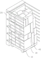
First, referring to fig. 1 and fig. 2, fig. 1 shows a schematic view of a load 40 carried on a load handling device provided in an embodiment of the present application, and fig. 2 shows a schematic view of a structure of the load handling device provided in the embodiment of the present application. Wherein, cargo handling device includes:
the trolley 10, the trolley 10 is provided with a bearing surface 101 for bearing the goods 40;
the protection assembly 20 is fixed on the trolley 10 and used for limiting the cargo 40 on the carrying surface 101, the protection assembly 20 includes a first protection member 21 on at least one side of the carrying surface 101 and a first telescopic member 212 fixed on the first protection member 21, a first limiting surface 213 is formed on one side of the first protection member 21 facing the cargo 40, the first telescopic member 212 has a telescopic direction, the telescopic direction is parallel to the first limiting surface 213, and the telescopic direction has a component parallel to the carrying surface 101.
This application is through setting up first guard piece 21 at the dolly 10 back, has effectively avoided the phenomenon that goods 40 topples over backward in the transfer process, and when another cargo handling device unloaded simultaneously, first extensible member 212 stretches into the back of goods 40 to prevent inclining the protection to the back of goods 40, can normally leave after making another cargo handling device unload to accomplish, has effectively avoided the phenomenon that cargo handling device leaves the in-process goods 40 and falls to damage after goods 40 shifts and unloads.
The cart 10 has a carrying surface 101 for carrying the goods 40, and is used for carrying the goods 40 to be transported, in order to facilitate the movement of the cart 10, the moving wheel 13 is installed below the cart 10, it can be understood that for the automated guided vehicle, the cart 10 may further have a driving mechanism for driving the moving wheel 13 to move, such as a driving motor and a transmission gear, and meanwhile, in order to facilitate the automatic navigation for carrying the goods 40, the cart 10 may further have an electromagnetic or optical automatic guiding device, so that the cart 10 can travel along a prescribed guiding path.
In some embodiments of the present application, to facilitate unloading of cargo 40 from cart 10, cart 10 may also have a lift mechanism by which cargo 40 is loaded or unloaded. As an example, as shown in fig. 2, the trolley 10 includes a first fork 11 and a second fork 12, a discharge slot is provided between the first fork 11 and the second fork 12, a moving wheel 13 is provided at the bottom of the first fork 11 and the second fork 12, a cargo 40 is stacked on the pallet 30, the lower portion of the pallet 30 has a space into which the first fork 11 and the second fork 12 extend, when loading the cargo 40, the lifting mechanism lowers the first fork 11 and the second fork 12, the first fork 11 and the second fork 12 extend into the bottom of the pallet 30 by moving the moving wheel 13, then raises the first fork 11 and the second fork 12, and the pallet 30 finally loaded with the cargo 40 is placed on the trolley 10, thereby completing the loading process of the cargo 40; when the cargo 40 is being unloaded, the first fork 11 and the second fork 12 are lowered by the lifting mechanism, the pallet 30 contacts the ground or the stacking platform, and the first fork 11 and the second fork 12 are withdrawn by the movement of the moving wheels 13, thereby completing the unloading process of the cart 10.
The protection assembly 20 is used for preventing at least the back side of the cargo 40 on the trolley 10 from tipping over, and in particular, the protection assembly 20 is fixed on the trolley 10 and used for limiting the cargo 40 on the bearing surface 101, wherein the protection assembly 20 comprises a first protection member 21 positioned on at least one side of the bearing surface 101 (for example, the back side of the cargo 40 as shown in fig. 1) and a first telescopic member 212 fixed on the first protection member 21, and a first limiting surface 213 is formed on one side of the first protection member 21 facing the cargo 40 to prevent the cargo 40 from tipping over from the first limiting surface 213.
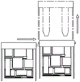
The first telescopic member 212 has a preset telescopic direction, the telescopic direction is parallel to the first limiting surface 213, and the telescopic direction has a component parallel to the bearing surface 101, for example, the telescopic direction may be parallel to the horizontal plane, so that the telescopic direction of the first telescopic member 212 horizontally extends toward the lateral direction of the trolley 10, so that the first telescopic member 212 laterally extends into the back surface of the cargo handling device transporting the cargo 40 when another cargo handling device unloads the cargo, and the back surface of the cargo 40 is protected against tilting. Referring to fig. 3, fig. 3 shows a schematic view of the cooperative unloading of two cargo-handling devices provided in the embodiment of the present application, since the backside of the cargo 40 is protected by the first telescopic member 212 extending thereinto when the cargo-handling device is unloaded, the cargo 40 will not topple backwards during the unloading and withdrawing of the cargo-handling device, and the purpose of preventing the backside of the cargo 40 from toppling over is achieved.
As an example, referring to fig. 4, fig. 4 shows a schematic structural diagram of the first protection part 21 and the cart 10 in the embodiment of the present application, wherein the first protection part 21 may be a protection plate 211 that is vertically placed, a surface of the protection plate 211 facing the cargo 40 forms a first limiting surface 213, that is, a surface of the protection plate 211 facing the back side of the cart 10 abuts against the back side of the cargo 40, so as to prevent the cargo 40 from falling down during transportation of the cargo 40. It is understood that the first protection member 21 may also be a guard rail formed by a plurality of protection rods 221, which can be used to block the back of the cargo 40, so as to prevent the cargo 40 from falling down during the transportation of the cargo 40.
In some embodiments of the present application, for example, for the embodiment where the first protection member 21 is the protection plate 211, as shown in fig. 4, the protection plate 211 has an avoidance groove 214 on a surface of the first limiting surface 213 for guiding the first expansion member 212 to extend into between the cargo 40 and the protection plate 211, when two cargo 40 transportation devices are arranged side by side, a back surface of the cargo 40 abuts against the first limiting surface 213 of the first protection member 21, and the first expansion member 212 extends into a back surface of the cargo 40 through the avoidance groove 214, so that the first protection member 21 can extend into the back surface of the cargo 40 while the first protection member 212 abuts against the back surface of the cargo 40, and thus the anti-tipping protection is performed in the unloading process.
Specifically, the avoiding groove 214 may be a groove with a square, rectangular, trapezoidal or circular cross section. As an example, referring to fig. 5, fig. 5 shows a schematic structural view of the first protection component 21 and the trolley 10 in the embodiment of the present application, wherein the avoidance groove 214 is an inverted trapezoid groove, where the inverted trapezoid groove means that the bottom edge of the trapezoid is located at the first limiting surface 213, that is, the trapezoid opening faces the back surface of the cargo 40, and the telescopic portion of the first telescopic component 212 fits in the avoidance groove 214, that is, the cross section of the first telescopic component 212 is a trapezoid, and the wider bottom edge of the first telescopic component faces the back surface of the cargo 40, so that the contact area between the first telescopic component 212 and the back surface of the cargo 40 can be increased, and the first telescopic component 212 can better protect the cargo 40 from falling.
It should be noted that the first extensible member 212 may adopt various extensible devices to achieve an extensible function, such as a hydraulic extensible rod, a pneumatic extensible rod, an electric extensible rod or a lead screw extensible mechanism, as an example, the first extensible member 212 includes a fixed portion and an extensible portion, a cavity for accommodating the first extensible member 212 is opened on a side surface of the protection plate 211, the fixed portion is located in the cavity of the protection plate 211, the extensible portion extends from the cavity to the outside of the protection plate 211, so that the first extensible member 212 is completely hidden inside the first protection member 21, and further, the reduction of the volume of the cargo handling device is facilitated.
Further, in order to achieve the anti-tipping protection of the two sides of the cargo 40 on the trolley 10, in some embodiments of the present application, the protection assembly 20 may further include second protection members 22 disposed on the two sides of the trolley 10, so that during the transportation of the cargo 40 by the trolley 10, the cargo 40 can be prevented from tipping to the left and right due to the protection of the second protection members 22 on the two sides, and the risk of tipping of the cargo 40 transported by the cargo handling device can be further reduced.
Specifically, the second protection member 22 may be a protection plate vertically disposed on the cart 10, and a surface of the protection plate faces to a side of the cart 10, and the protection plate is configured to abut against two sides of the cargo 40, so as to prevent the cargo 40 from falling down during transportation of the cargo 40. It is understood that the second protection member 22 may also be a guard rail formed by a plurality of guard bars 221, which can prevent the cargo 40 from moving to both sides during the transportation of the cargo 40 by the guard rail.
In order to allow the cargo handling apparatus to be normally withdrawn through the second shielding member 22 after the first telescopic member 212 is extended into the backside of the cargo 40, in some embodiments of the present application, the second shielding member 22 has a transverse through slot 222 for allowing the first telescopic member 212 to pass transversely therethrough, and in an example of a guard rail in which the second shielding member 22 is composed of a plurality of guard bars 221, the transverse through slot 222 for allowing the first telescopic member 212 to pass therethrough is formed between adjacent guard bars 221. In some embodiments, to achieve the fixation of the second protection member 22, the second protection member 22 is connected with the first protection member 21, for example, an end of the protection rod 221 adjacent to the first protection member 21 is connected with the first protection member 21. It is understood that when the second protection member 22 is a protection plate, the second protection member 22 may be opened with a plurality of transverse through slots 222 to achieve the purpose that the first expansion member 212 may pass through the second protection member 22.
In some embodiments of the present disclosure, a plurality of guard bars 221 may be disposed between adjacent transverse through slots 222, for example, as shown in fig. 1, two guard bars 221 are disposed between adjacent transverse through slots 222, and further, since the first guard 21 does not pass through the two guard bars 221, the two guard bars 221 may be connected to each other, so as to further enhance the structural strength of the guard bars 221 and avoid the situation that the guard bars 221 cannot bear the acting force generated by the falling of the cargo 40.
Further, on the basis that the above-mentioned embodiment achieves the anti-tipping of the back side and the left and right sides of the cargo 40, in order to prevent the cargo 40 from tipping forward during transportation, as shown in fig. 4 or fig. 5, the cart 10 has the carrying surface 101 disposed obliquely to the first protection member 21, and since the carrying surface 101 has a backward-tipping angle, when the cargo 40 is prevented on the carrying surface 101, the cargo 40 slides backward and abuts against the first protection member 21, thereby preventing the cargo 40 from tipping forward. For example, the angle between the bearing surface 101 and the horizontal plane may be 5 °, but is not limited thereto, and may also be 5 ° to 10 °, for example.
It should be noted that the above description of the cargo handling apparatus is only for the sake of clarity of the verification process of the present application, and those skilled in the art can make equivalent modifications to the above apparatus under the guidance of the present application, for example, the cargo handling apparatus may further include a communication device to exchange information with the electromagnetic track on the ground to obtain moving, loading or unloading instructions.
In order to better implement the above-mentioned cargo handling device, on the basis of the cargo handling device provided in the embodiment of the present application, the present application further provides a method for unloading, where the method for unloading is applied to a cargo handling system, the cargo handling system includes at least two cargo handling devices according to any one of the above-mentioned embodiments, and referring to fig. 6, fig. 6 shows a schematic flow chart of the method for unloading in the embodiment of the present application, where the method for unloading includes:
step S601, controlling a first cargo carrying device and a second cargo carrying device to arrive at destinations and arrange side by side, wherein the first cargo carrying device and the second cargo carrying device carry cargos 40 to be placed;
the destination refers to a discharge location of the goods 40, for example, in an express loading scenario shown in fig. 7, the destination may be a truck compartment, a designated storage location, and the like, where the goods 40 to be placed may refer to stacked express packages. It will be appreciated that the loading of the load 40 onto the cart 10 is completed prior to unloading, and in particular, the loading of the load 40 may be completed by lowering the first fork 11 and the second fork 12 via the lifting mechanism, then extending the first fork 11 and the second fork 12 into the bottom of the pallet 30, and lifting the same to complete the loading process.
In some embodiments of the present application, the control of the first and second cargo-moving devices to the destination side by side may be achieved by electromagnetic or optical automatic guiding devices, such as electromagnetic rails attached to the floor, and the first and second cargo-moving devices moving and operating according to the information from the electromagnetic rails. As an example, the second cargo handling device may be controlled to move to the destination, and then the first cargo handling device may be controlled to move to the destination and be arranged side by side with the second cargo handling device; as another example, the first and second cargo handling devices may also be controlled to move side by side and reach the destination at the same time.
Step 602, controlling the first telescopic member 212 of the first cargo handling device to extend out towards the second cargo handling device, and controlling the first telescopic member 212 to extend into the back side of the cargo 40 carried by the second cargo handling device and to perform anti-tilt protection on the back side of the cargo 40;
after the first cargo handling device and the second cargo handling device reach the destination and are arranged side by side, the first telescoping member 212 of the first cargo handling device can be controlled to extend towards the second cargo handling device. As an example, when the first telescopic member 212 is a hydraulic telescopic rod, the pump may be controlled to introduce liquid into the hydraulic telescopic rod, so as to drive the first telescopic member 212 to extend and retract. It can be understood that the timing of the first telescopic member 212 can be determined by the sensing device, for example, when the first cargo handling device and the second cargo handling device move to the destination, the electromagnetic track corresponding to the ground at the destination indicates the first telescopic member 212 to be telescopic, and for example, when the laser correlation sensors respectively disposed on the first cargo handling device and the second cargo handling device are aligned, the telescopic movement of the first telescopic member 212 can be controlled.
Step S603, controlling the first cargo handling device and/or the second cargo handling device to move, so that the second cargo handling device completes the unloading process.
After the first telescoping member 212 of the first cargo handling device is extended towards the second cargo handling device, the unloading process of the second cargo handling device can be determined to begin. Specifically, the unloading process of the second cargo handling device may include:
controlling the first cargo handling device to move along a first direction, wherein the first direction is a direction in which the back surface of the cargo 40 points to the front surface of the cargo 40; and/or
The second load handling device is controlled to move in a second direction, which is the direction in which the front side of the load 40 points towards the back side of the load 40.
As shown in fig. 8, taking the second cargo handling device as an example of moving, the first cargo handling device is fixed, the second cargo handling device lifting mechanism lowers the first forks 11 and the second forks 12, the second cargo handling device moves backward after the pallet 30 with the stacked cargo 40 falls to the ground, and the first forks 11 and the second forks 12 withdraw from the pallet 30, thereby completing the unloading process.
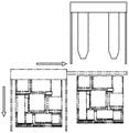
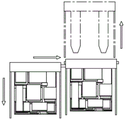
As another example, as shown in fig. 9, the first cargo handling device is moved and the second cargo handling device is stationary, and the cargo 40 is pushed down the cart 10 of the second cargo handling device by the first telescoping member 212 of the first cargo handling device. As a further example, as shown in fig. 10, it is also possible to move the first and second load handling devices simultaneously in opposite directions, and by relative movement push the load 40 down the trolley 10 of the second load handling device.
To facilitate the tipping-off process of the first cargo-handling device after the unloading process of the second cargo-handling device is completed, in some embodiments of the present application, the method further comprises:
controlling the first cargo handling device and the second cargo handling device to be arranged side by side again;
controlling the first telescopic member 212 of the second cargo handling device to extend out towards the first cargo handling device, wherein the first telescopic member 212 extends into the back of the cargo 40 carried by the first cargo handling device, and performing anti-tilt protection on the back of the cargo 40;
and controlling the first cargo handling device and/or the second cargo handling device to move so that the first cargo handling device completes the unloading process.
Finally, the unloading process is completed through the cooperation process of the first cargo carrying device and the second cargo carrying device, so that the two cargo carrying devices can normally leave after unloading, and the phenomenon that the cargo carrying devices leave the process after the cargo 40 is transferred and unloaded, and the cargo 40 falls and is damaged is effectively avoided.
In order to better implement the cargo handling device in the embodiment of the present application, on the cargo handling device, a cargo handling system is further provided in the embodiment of the present application, the cargo handling system includes a controller, a bus, and the cargo handling device in any one of the embodiments, wherein:
the controller is a control center of the cargo handling system, connects various parts of the whole system by using various interfaces and lines, and executes various functions of the device by running or executing stored programs, thereby performing overall control on the system and realizing a cargo 40 handling process. Alternatively, the controller may include one or more processing cores; the controller may be a Central Processing Unit (CPU), other general purpose controller, a Digital Signal Processor (DSP), an Application Specific Integrated Circuit (ASIC), an off-the-shelf Programmable Gate Array (FPGA) or other Programmable logic device, a discrete Gate or transistor logic device, a discrete hardware component, a Programmable logic controller (PLC controller), etc.
A bus is a communication network of the cargo handling system that allows communication between various parts of the system to facilitate the transfer of information and/or data. Optionally, the industrial communication network may include wired communication, such as a field bus, an industrial ethernet, an industrial Internet (TSN), and the like, and may also include wireless communication, such as a Narrow Band Internet of Things (NB-IoT), and the like.
The cargo handling device is a device for performing a handling process of the cargo 40, and is connected to the controller through a bus to receive a control command from the controller. Specifically, the cargo handling device comprises a trolley 10, moving wheels 13 are arranged below the trolley 10, and the trolley 10 is used for carrying cargos 40 to be transported; the protection assembly 20, the protection assembly 20 includes a first protection member 21 surrounding the back side of the trolley 10, the first protection member 21 is provided with a first telescopic member 212, the first telescopic member 212 is telescopic towards the side of the trolley 10, so that the first telescopic member 212 can extend into the back side of the cargo 40 when another cargo handling device unloads, and the back side of the cargo 40 can be protected from tilting.
It should be noted that the above description of the cargo handling system is only for the sake of clarity of the verification process of the present application, and those skilled in the art can make equivalent modifications to the above system under the guidance of the present application, for example, the cargo handling system may further include a display to display the position, the amount of power, the load capacity, etc. of each cargo handling device.
In the above embodiments, the descriptions of the respective embodiments have respective emphasis, and parts that are not described in detail in a certain embodiment may refer to the above detailed descriptions of other embodiments, and are not described herein again.
Having thus described the basic concept, it will be apparent to those skilled in the art that the foregoing detailed disclosure is to be considered merely illustrative and not restrictive of the broad application. Various modifications, improvements and adaptations to the present application may occur to those skilled in the art, although not explicitly described herein. Such modifications, improvements and adaptations are proposed in the present application and thus fall within the spirit and scope of the exemplary embodiments of the present application.
Also, this application uses specific language to describe embodiments of the application. Reference throughout this specification to "one embodiment," "an embodiment," and/or "some embodiments" means that a particular feature, structure, or characteristic described in connection with at least one embodiment of the present application is included in at least one embodiment of the present application. Therefore, it is emphasized and should be appreciated that two or more references to "an embodiment" or "one embodiment" or "an alternative embodiment" in various places throughout this specification are not necessarily all referring to the same embodiment. Furthermore, certain features, structures, or characteristics may be combined as suitable in one or more embodiments of the application.
It should be noted that in the foregoing description of embodiments of the application, various features are sometimes grouped together in a single embodiment, figure, or description thereof for the purpose of streamlining the disclosure aiding in the understanding of one or more of the embodiments. This method of disclosure, however, is not intended to require more features than are expressly recited in the claims. Indeed, the embodiments may be characterized as having less than all of the features of a single embodiment disclosed above.
The cargo handling device, the cargo handling system, and the unloading method provided in the embodiments of the present application are described in detail above, and specific examples are applied herein to illustrate the principles and embodiments of the present invention, and the description of the embodiments above is only used to help understand the method and the core ideas of the present invention; meanwhile, for those skilled in the art, according to the idea of the present invention, there may be variations in the specific embodiments and the application scope, and in summary, the content of the present specification should not be construed as a limitation to the present invention.