CN115190850A - Internal delivery box - Google Patents
Internal delivery box Download PDFInfo
- Publication number
- CN115190850A CN115190850A CN202080097844.6A CN202080097844A CN115190850A CN 115190850 A CN115190850 A CN 115190850A CN 202080097844 A CN202080097844 A CN 202080097844A CN 115190850 A CN115190850 A CN 115190850A
- Authority
- CN
- China
- Prior art keywords
- base
- vehicle container
- vehicle
- housing
- seat
- Prior art date
- Legal status (The legal status is an assumption and is not a legal conclusion. Google has not performed a legal analysis and makes no representation as to the accuracy of the status listed.)
- Granted
Links
Images


Classifications
-
- B—PERFORMING OPERATIONS; TRANSPORTING
- B60—VEHICLES IN GENERAL
- B60R—VEHICLES, VEHICLE FITTINGS, OR VEHICLE PARTS, NOT OTHERWISE PROVIDED FOR
- B60R7/00—Stowing or holding appliances inside vehicle primarily intended for personal property smaller than suit-cases, e.g. travelling articles, or maps
- B60R7/04—Stowing or holding appliances inside vehicle primarily intended for personal property smaller than suit-cases, e.g. travelling articles, or maps in driver or passenger space, e.g. using racks
- B60R7/043—Stowing or holding appliances inside vehicle primarily intended for personal property smaller than suit-cases, e.g. travelling articles, or maps in driver or passenger space, e.g. using racks mounted on or under a seat
-
- B—PERFORMING OPERATIONS; TRANSPORTING
- B60—VEHICLES IN GENERAL
- B60R—VEHICLES, VEHICLE FITTINGS, OR VEHICLE PARTS, NOT OTHERWISE PROVIDED FOR
- B60R11/00—Arrangements for holding or mounting articles, not otherwise provided for
- B60R2011/0042—Arrangements for holding or mounting articles, not otherwise provided for characterised by mounting means
- B60R2011/0049—Arrangements for holding or mounting articles, not otherwise provided for characterised by mounting means for non integrated articles
- B60R2011/005—Connection with the vehicle part
- B60R2011/0059—Connection with the vehicle part using clips, clamps, straps or the like
-
- B—PERFORMING OPERATIONS; TRANSPORTING
- B60—VEHICLES IN GENERAL
- B60R—VEHICLES, VEHICLE FITTINGS, OR VEHICLE PARTS, NOT OTHERWISE PROVIDED FOR
- B60R11/00—Arrangements for holding or mounting articles, not otherwise provided for
- B60R2011/0042—Arrangements for holding or mounting articles, not otherwise provided for characterised by mounting means
- B60R2011/0049—Arrangements for holding or mounting articles, not otherwise provided for characterised by mounting means for non integrated articles
- B60R2011/005—Connection with the vehicle part
- B60R2011/0061—Connection with the vehicle part using key-type connections
Landscapes
- Engineering & Computer Science (AREA)
- Mechanical Engineering (AREA)
- Vehicle Step Arrangements And Article Storage (AREA)
Abstract
用于车辆容器(104)的基座,其包含安装至车辆座椅的主体(202),和嵌入主体(202)内的附着元件(208),所述附着元件(208)包含安装元件(210,212)以接收车辆容器(104)的一部分(242),并且其中所述安装元件(210,212)保持所述车辆容器(104)的部分(246)被接收时的竖直位置。

A base for a vehicle container (104) comprising a body (202) mounted to a vehicle seat, and an attachment element (208) embedded within the body (202), the attachment element (208) comprising a mounting element (210) , 212) to receive a portion (242) of a vehicle container (104), and wherein the mounting elements (210, 212) maintain an upright position in which the portion (246) of the vehicle container (104) is received.
Description
Cross Reference to Related Applications
This application claims the benefits and priority of U.S. patent application serial No. 16/731,628 entitled "interface DELIVERY BOX," filed 2019, 12, 31, which is incorporated herein by reference in its entirety.
Technical Field
The present disclosure relates generally to vehicular transportation of cargo, and more particularly to an apparatus and method for providing a container to be installed within a vehicle for the transportation of cargo.
Background
Vehicles have been the primary mode of transportation in many societies. In addition to carrying passengers, vehicles have become a means for transporting items and delivering items. As ride-sharing and ride-owning companies grow and expand services, passenger vehicles have become a common means of delivering items.
Drawings
The following figures and accompanying description are provided to provide some examples for an understanding of the subject matter disclosed herein. In all figures, a component may be labeled with the same reference numeral to indicate that the component is the same component in all figures using the same reference numeral.
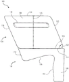
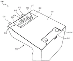
Fig. 1 provides an example vehicle container unit according to some embodiments of the present disclosure.
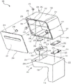
Fig. 2 provides an exploded perspective view of the example vehicle container unit of fig. 1, according to some embodiments of the present disclosure.
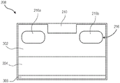
Fig. 3 provides a top view of the example attachment member shown in fig. 2, according to some embodiments of the present disclosure.
Fig. 4 provides a perspective view of the example mounting element shown in fig. 2, according to some embodiments of the present disclosure.
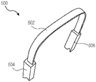
Figure 5 provides an example tether according to some embodiments of the present disclosure.
Fig. 6 provides an example pedestal arrangement according to some embodiments of the present disclosure.
Fig. 7 provides an example vehicle container unit arrangement according to some embodiments of the present disclosure.
Fig. 8 provides another example vehicle container unit arrangement, according to some embodiments of the present disclosure.
Fig. 9 provides another example vehicle container unit, according to some embodiments of the present disclosure.
Fig. 10 provides another arrangement of the example vehicle container unit of fig. 9, according to some embodiments of the present disclosure.
Fig. 11 provides an example vehicle container unit arrangement according to some embodiments of the present disclosure.
FIG. 12 illustrates an example autonomous vehicle according to embodiments described herein.
Fig. 13 illustrates example components that may be implemented within an autonomous vehicle according to embodiments described herein.
Detailed Description
SUMMARY
The following description and the annexed drawings set forth in detail certain illustrative examples of the features of the subject matter described herein. The present disclosure relates generally to vehicular transportation of cargo, and more particularly to an apparatus and method for providing a container to be installed within a vehicle for the transportation of cargo. As will be appreciated by one skilled in the art, the features described herein may be embodied in various ways-for example, as methods, apparatus, systems, and/or otherwise.
The following detailed description presents various descriptions of certain specific embodiments. The innovations described herein may, however, be embodied in many different forms, for example, as defined and covered by the claims and/or selected examples. In the following description, reference is made to the accompanying drawings wherein like reference numerals may indicate identical or functionally similar elements. It will be understood that the elements illustrated in the figures are not necessarily drawn to scale. Further, it will be understood that certain embodiments may include more elements than illustrated in the figures and/or a subset of the elements illustrated in the figures. Furthermore, some embodiments may incorporate any suitable combination of features from two or more of the figures.
Other features and advantages of the disclosure will be apparent from the following description and from the claims.
Description of the preferred embodiment
The vehicle container unit described herein may facilitate transporting items within a vehicle. For example, the vehicle container unit may facilitate transporting items on a vehicle seat while reducing concern for damage to items or other items within the passenger compartment of the vehicle. Vehicle container units may be used in situations where items are transported within the passenger compartment of a vehicle, as often occurs in ride-sharing situations, and autonomous vehicles. The vehicle container unit can be used without having to change the vehicle.
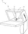
Fig. 1 provides an example vehicle container unit 100 according to some embodiments of the present disclosure. The vehicle container unit 100 may be used in a vehicle that transports goods. In particular, the vehicle container unit 100 may have a space enclosed within the vehicle container unit 100 into which items may be placed for transport within the vehicle, as further described throughout this disclosure. In some cases, the vehicle container unit 100 may be referred to as an interior delivery box.
The vehicle container unit 100 may include a base 102 and a vehicle container 104. The base 102 may be mounted to a vehicle seat and facilitates installation of the vehicle container 104 within a vehicle. In particular, the vehicle container 104 may be mounted to the base 102, wherein the base 102 mounts the vehicle container 104 to a seat and maintains the position of the vehicle container 104 when installed. Although a particular vehicle container 104 is described throughout this disclosure, it should be understood that the base 102 may be used to mount other forms of vehicle containers and/or other structures to be used in a vehicle.
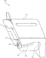
The base 102 may have a surface 106 that is placed over the seat to which the base 102 and vehicle container 104 are to be mounted. The surface 106 may abut the seat and may be contoured to match the contour of the seat or a portion thereof such that the surface 106 may conform to the seat or a portion thereof when positioned on the seat. As discussed further throughout this disclosure, the base 102 may include attachment elements for mounting the base 102 to a seat, wherein the surface 106 may be held against the seat when the base 102 is mounted to the seat. The base 102 may further have a surface 114 on which the vehicle container 104 is to be positioned. The surface 114 may be located on an opposite side of the base 102 from the surface 106. The surface 114 may be substantially (within 10 degrees) parallel to a contact plane of the vehicle with a surface on which the vehicle is located, wherein the contact plane may contain an imaginary line drawn between locations where wheels of the vehicle contact the surface on which the vehicle is located.
The base 102 may further have a portion 108 that is located forward of the front edge of the seat and may extend downward from the seat. In particular, if the individual is properly seated in the seat, the portion 108 may be located where the individual's legs will extend. In some embodiments, the surface 110 of the portion 108, or portions thereof, may abut and extend along the front side of the seat and/or the infrastructure on which the seat is positioned. In these embodiments, the surface 110, or portions thereof, may be contoured to match the contour of the front side of the seat and/or the infrastructure upon which the seat is positioned, wherein the surface 110 may mate with the front side of the seat and/or the infrastructure when the base 102 is mounted to the seat. In some embodiments, the surface 112 of the base 102 may abut and extend along the back of the seat. In these embodiments, the contour of the surface 112 can be designed to match the contour of the back of the seat, wherein the surface 112 can mate with the back of the seat when the base 102 is mounted to the seat.
The vehicle container 104 may be mounted to a surface 114 of the base 102. In particular, when the vehicle container 104 is mounted to the base 102, a surface 116 of the vehicle container 104 may abut the surface 114 of the base 102 and extend along the surface 114. The vehicle container 104 may include a mounting mechanism that may be coupled to a mounting mechanism of the base 102 to mount the vehicle container 104 to the base 102, as further described throughout this disclosure, wherein the surface 116 may remain against the surface 114 when the vehicle container 104 is mounted to the base 102.
The vehicle container 104 may have a surface 118 that abuts the back of the seat when the base 102 and vehicle container 104 are mounted to the seat. The surface 118 may extend at the same angle as the back of the seat such that when the vehicle container 104 is installed, the surface 118 extends along the back of the seat. In some embodiments, the contour of the surface 118 may be further designed to match the contour of the back of the seat, wherein the surface 118 may be mated with the back of the seat when the vehicle container 104 is mounted to the seat.
The vehicle container 104 may further have a surface 120 located on a side of the vehicle container 104 opposite the seat. In particular, the surface 120 may be located on an opposite side of the vehicle container 104 from the surface 118. In some embodiments, the surface 120 may be angled toward the back of the seat. For example, in some embodiments, the surface 120 may extend at an angle 122 of about (within 10 degrees) 67.5 degrees from the surface 116. In some embodiments, surface 120 may be about (within 10 degrees) parallel to surface 118. In other embodiments, the angle 122 may be less than 67.5 degrees or greater than 67.5 degrees. The angle 122 of the surface 120 may be provided to another seat in front of the seat in which the vehicle container unit 100 is installed. In some embodiments, the angle 122 of the surface 120 may allow another seat in front of the seat in which the vehicle container unit 100 is installed to be tilted about (within 5 degrees) 5 degrees from an upright position.
The vehicle container 104 may further have a surface 124 located opposite the base 102. In particular, the surface 124 may be located on an opposite side of the vehicle container 104 from the surface 116. In some embodiments, surface 124 may be about (within 10 degrees) parallel to surface 116. In some embodiments, surface 124 may be located at a distance of about (within 10 millimeters (mm)) 393.70 mm from surface 116. Thus, in these embodiments, the height 126 of the vehicle container 104 may be about (within 10 mm) 393.70 mm. In other embodiments, the height 126 of the vehicle container 104 may be less than 393.70 mm or greater than 393.70 mm. The height 126 of the vehicle container 104 may allow a vehicle operator to view the vehicle container 104 from a rear window of the vehicle. In other embodiments, the vehicle container 104 may extend to a ceiling of the vehicle in which the vehicle container 104 is to be positioned. In these embodiments where the vehicle container 104 extends to the ceiling, the surface 124 may abut the ceiling of the vehicle. Further, in these embodiments, surface 124 may be contoured to conform to the roof of the vehicle.
The vehicle container 104 may have a door 128. The door 128 may be opened to expose a space enclosed within the vehicle container 104 for transporting cargo. The door 128 may include a handle 130 to facilitate opening and closing of the door 128. In some embodiments, the handle 130 and/or the door 128 may include an indication that a user may interact with the handle 130. In the illustrated embodiment, the door 128 is illustrated on a side of the vehicle container 104 corresponding to the right side of the seat. In these embodiments, the vehicle container unit 100 may be intended to be positioned in a seat, toward the right side of the vehicle, such that the door 128 is adjacent to the door on the right side of the vehicle. In some embodiments, when the door 128 is positioned in a vehicle, it may be aligned with a window of the vehicle. In these embodiments where the door 128 is aligned with a window, when the window is open, the door 128 may be accessed through the window without opening the vehicle door, and when the door 128 is open, the enclosed space within the vehicle container 104 may be accessed through the open window. Thus, items may be retrieved and/or placed within the space within the vehicle container 104 without having to open the doors of the vehicle. In other embodiments, the door 128 may be located on an opposite side of the vehicle container 104, which corresponds to the left side of the seat. In these embodiments, the vehicle container unit 100 may be intended to be positioned in a seat, toward the left side of the vehicle, such that the door 128 is adjacent the door to the left side of the vehicle. It should be understood that while the door 128 is described in some embodiments as being intended to be adjacent to a door of an automobile, the position of the door 128 relative to the automobile door should not be construed as limiting, and the vehicle container unit 100 may be mounted in a seat toward either side of the vehicle, regardless of which side of the vehicle container unit 104 the door 128 is located, and the vehicle container unit 100 may be mounted to the seat with the door 128 pointing toward the center of the vehicle. In other embodiments, the door 128 may be located at the front of the vehicle container 104 corresponding to the surface 120, at the top of the vehicle container 104 corresponding to the surface 124, on either side of the vehicle container 104, or some combination thereof.
Fig. 2 provides an exploded perspective view of the example vehicle container unit 100 of fig. 1, according to some embodiments of the present disclosure. In particular, fig. 2 illustrates separate vehicle container unit 100 components, wherein one or more components may be embedded within other components of the vehicle container unit 100, as further described.
The vehicle container unit 100 may include a main body 202. The body 202 may be a portion of the seat 102 (fig. 1) and defines the shape of the seat 102. For example, the body 202 may have the shape described with respect to the seat 102 in fig. 1 and include a surface. The body 202 may have a surface 106 that abuts the seat, a surface 110 that abuts the front of the seat and/or the infrastructure on which the seat is positioned, and a surface 112 that abuts the back of the seat when the body 202 is mounted to the seat. The body 202 may further include a surface 114 on which the vehicle container 104 (fig. 1) is to be mounted. The body 202 may have a groove 204 formed in the surface 114. In particular, the groove 204 may extend from the surface 114 into the body 202. The groove 204 may be located toward a first end 206 of the surface 114.
The body 202 may contain a condensable material that may retain shape until some force when the material may condense. The condensable materials may help prevent damage to other objects within the vehicle. The condensable material of the body 202 may comprise a foam material. In some embodiments, the foam material may comprise expanded polypropylene (EPP) foam. In some embodiments, the density of the EPP foam may be about (within 0.5 pounds per cubic foot (lb/cuft)) 1.9 lb/cuft. EPP foams can exhibit energy absorption, multiple impact resistance, thermal insulation, buoyancy, water and chemical resistance, and high strength to weight ratios. Thus, the EPP foam may allow the body 202 to retain shape while being light enough to be easily installed and removed from the seat.
The vehicle container unit 100 may further include an attachment member 208. The attachment member 208 may be embedded within the body 202. For example, the attachment element 208 may be embedded within the body 202 toward the first end 206 of the surface 114. The attachment element 208 may facilitate mounting the base 102 to a seat. The attachment member 208 may have a shape that matches the shape of the recess 204 and may be embedded within the portion of the body 202 having the recess 204. Accordingly, traction element 208 may be positioned adjacent to groove 204, wherein groove 204 is surrounded by traction element 208 based on the shape and position of traction element 208 relative to groove 204.
The attachment member 208 may have one or more apertures 216 formed in the attachment member 208. An aperture 216 may extend through the attachment member 208 and the body 202. For example, the aperture 216 may extend from the surface 114 to the surface 106, wherein the aperture 216 abuts the groove 204 formed in the surface 114. The tether may extend through the aperture 216 and connect to one or more anchors of the seat to mount the base 102 to the seat. In other embodiments, a tether may be coupled to attachment element 208. In some of these other embodiments, aperture 216 may be omitted and the tether connected to attachment element 208.
The attachment member 208 may include a mounting member for mounting the vehicle container 104 to the base 102. The mounting element may receive a portion of the vehicle container 104 and may maintain (within 1 cm) the vertical position of the portion of the vehicle container 104 when the portion of the vehicle container 104 is located within the mounting element. The mounting element may include an extension 210 and a recess 212 within the extension 210. In the illustrated embodiment, the extension 210 may form a rectangle around the recess 212 to surround the recess 212. The recess 212 may receive the portion of the vehicle container 104, and the extension 210 may maintain a vertical position of the portion of the vehicle container 104 when the portion of the vehicle container 104 is within the recess 212.
The vehicle container unit 100 may further include a first mounting plate 214. The first mounting plate 214 may be embedded within the body 202. First mounting plate 214 may be positioned toward a second end 222 of surface 114, where second end 222 is at an opposite end of surface 114 from first end 206. The first mounting plate 214 may engage a portion of the vehicle container 104 and, when engaged, may maintain (within 1 cm) the horizontal position of the portion of the vehicle container 104. The first mounting plate 214 may include one or more extrusions 218 that engage a portion of the vehicle container 104. In the illustrated embodiment, extrusion 218 has a circular shape, but it should be understood that in other embodiments extrusion 218 may have a different shape. When first mounting plate 214 is embedded within body 202, extrusion 218 may extend approximately (within 5 degrees) perpendicular to surface 114. In some embodiments, extrusion 218 may extend out of body 202 and a portion of extrusion 218 may be exposed. In other embodiments, extrusions 218 are embedded within body 202 and may cause portions of body 202 corresponding to extrusions 218 to be extruded from surface 114.
The first mounting plate 214 may further include an attachment mechanism 220. The attachment mechanism 220 may be used to attach the clamping element to the attachment mechanism 220. For example, in some embodiments, the attachment mechanism 220 may include an aperture, wherein a portion of the clamping element may extend through the aperture to attach the clamping element to the first mounting plate 214. The attachment mechanism 220 may extend outside of the body 202 beyond the second end 222 of the surface 114 and may be exposed. In some embodiments, the first mounting plate 214 may omit the attachment mechanism 220. In these embodiments, the attachment mechanism 220 and/or the clamping element may be coupled to the body 202 by another structure toward the second end 222 of the surface 114.
The attachment member 208 and the first mounting plate 214 may comprise a rigid material. For example, the attachment member 208 and the first mounting plate 214 may comprise a plastic material. The attachment element 208 and the first mounting plate 214, which are plastic materials, may provide rigidity for mounting the base 102 to the seat and the vehicle container 104 to the base 102. In some embodiments, the plastic material of attachment member 208 and first mounting plate 214 may comprise Acrylonitrile Styrene Acrylate (ASA).
The body 202, the attachment member 208, and the first mounting plate 214 may form the base 102. In particular, the body 202 with the attachment member 208 and the first mounting plate 214 embedded within the body 202 may form the seat 102. The attachment member 208 may facilitate mounting the base 102 to a seat. The attachment member 208 and the first mounting plate 214 may facilitate mounting the vehicle container 104 to the base 102.
The vehicle container unit 100 may further include an outer housing 224 having a door 226. The housing 224 with the door 226 may be part of the vehicle container 104 and define the shape of the vehicle container 104. For example, the housing 224 with the door 226 may have a shape as described with respect to the vehicle container 104 in fig. 1 and include a surface. The housing 224 may have a surface 116 that abuts the base 102 when the vehicle container 104 is mounted to the base 102. In particular, the surface 116 may abut the surface 114 when the vehicle container 104 is mounted to the base. The housing 224 may further include a surface 118 that abuts a back of a seat on which the vehicle container unit 100 is mounted, a surface 120 opposite the surface 118, and a surface 124 opposite the surface 116.
The housing 224 may enclose a space 228. The space 228 may be used for storage and transport of items, wherein items may be placed in the space and enclosed within the space 228 when the door 226 is closed. An inner wall 230 of the housing 224 may abut the space 228 and define the dimensions of the space 228. For example, the space 228 may have a height 232 of about (within 10 mm) 317.5 mm defined by a top wall of the inner wall 230 and a bottom wall of the inner wall 230. The space 228 may further have a length 234 of about (within 10 mm) 524.065 mm defined by a front wall of the inner wall 230 opposite the surface 120 and a rear wall of the inner wall 230 opposite the surface 118. The space 228 may further have a width 236 of about (within 10 mm) 446.61 mm defined by one of the interior walls 230 on the door 226 and the other of the interior walls 230 opposite the door 226. The inner wall 230 may form an angle 240 of about (within 5 degrees) 112.5 degrees between the bottom wall of the inner wall 230 and the back wall of the inner wall 230, and an angle 238 between the top wall of the inner wall 230 and the back wall of the inner wall 230. The inner wall 230 may be a quadrilateral in which the walls opposite the inner wall 230 are substantially (within 5 degrees) parallel and the diagonal angles formed by the inner wall 230 are substantially (within 5 degrees) equal. While the dimensions of the inner wall 230 and the space 228 of the illustrated embodiment are provided, it should be understood that these dimensions provide one example of dimensions, and that these dimensions may be different in other embodiments.
The housing 224 and door 226 may contain condensable materials that may retain shape until some force is possible where the materials may condense. The condensable materials may help prevent damage to other objects within the vehicle. The condensable material of the housing 224 and door 226 may comprise a foam material. In some embodiments, the foam material may comprise EPP foam. The EPP foam of the housing 224 and door 226 may be of a variety of different densities, or may both be of one density. For example, in some embodiments, the door 226 and the portion of the housing 224 surrounding the door 226 when the door 226 is closed may have a density of about (within 0.5 lb/cupt) 3.9 lb/cupt, and the remainder of the housing 224 may have a density of about (within 0.5 lb/cupt) 1.9 lb/cupt. EPP foams can exhibit energy absorption, multiple impact resistance, thermal insulation, buoyancy, water and chemical resistance, and high strength to weight ratios. Thus, the EPP foam may allow the housing 224 to retain shape while being light enough to be easily installed and removed from the seat. Additionally, the EPP foam may help maintain the temperature within the space 228 and provide for easy removal of any spillage that may occur from items being transported within the enclosure 224.
The housing 224 may include one or more magnets for holding the door 226 in the closed position in the absence of an external force. In particular, when the door 226 is positioned against the remainder of the housing 224, the magnet may hold the door 226 closed against the remainder of the housing 224. The door 226 may remain in the closed position until an amount of external force away from the remainder of the housing 224 is applied to the door 226 that exceeds the amount of magnetic force applied to the door 226 by the magnet to maintain the door 226 in the closed position. In the illustrated embodiment, the first magnet 254 may be embedded in the housing 224 while the second magnet 256 is embedded within the door 226 to maintain the door 226 in the closed position. A bottom edge 258 of door 226 may be rotationally coupled to an edge 260 of surface 116 via a hinge. In some embodiments, the hinge may comprise a multi-hinge. The first magnet 254 may be embedded within the housing 224 at an edge 262 of the surface 124, where the edge 262 abuts the door 226 and is positioned relative to the edge 260 having the hinge. The second magnet 256 may be embedded near a top edge 264 of the door 226, the top edge 264 being opposite the bottom edge 258 having the hinge. When the door 226 is closed, the first and second magnets 254, 256 may be positioned adjacent to each other and may generate a magnetic force that maintains the door 226 in a closed position. While magnets are described as being used to hold the door in the closed position, it should be understood that in other embodiments, one or more of the magnets may be replaced with a material (e.g., metal) that the magnets may act on to create a magnetic force. For example, in other embodiments, one of the first and second magnets 254, 256 may comprise a magnet and the other of the first and second magnets 254, 256 may comprise a material upon which the magnet may act.
The housing 224 may further include one or more magnets to hold the separation element in certain positions (as further described throughout this disclosure). For example, in the illustrated embodiment, the housing 224 may include a first magnet 266 and a second magnet 268. The first magnet 266 may be embedded within the housing 224 toward the end of the surface 124. The first magnet 266 may hold the separation element in a first position against one of the inner walls 230 of the housing 224. The second magnet 268 may be embedded within the housing toward the center of the surface 116. The second magnet 268 may hold the dividing element in the second position of the subdivision space 228. The first and second magnets 266, 268 may interact with another magnet embedded within the spacer element when in the respective positions to hold the spacer element in the respective positions. When in the respective position, the first and second magnets 266, 268 may be aligned with the magnets in the separation element to generate a magnetic force to hold the separation element in that position. For example, when the separator element is in the first position, the first magnet 266 may be aligned with a magnet in the separator element and generate a magnetic force that holds the separator element in the first position. When the separation element is in the second position, the second magnet 268 may align with a magnet in the separation element and generate a magnetic force that holds the separation element in the second position. Although magnets are described as being used to hold the separation element in these positions, it should be understood that in other embodiments one or more of the magnets may be replaced with a material (e.g., metal) that the magnets can act on to create a magnetic force. Furthermore, in other embodiments, one or more magnets for holding the separating element in these positions may be omitted and/or embedded in different positions. For example, in embodiments where the separation element is omitted from the housing 224, the magnet holding the separation element may be omitted.
The vehicle container unit 100 may further include a mounting element 242. The mounting element 242 may be embedded within the housing 224. In particular, the mounting element 242 may be embedded within the housing 224 at the surface 116. The mounting element 242 may be positioned toward a first end 244 of the surface 116. The mounting element 242 may include an arm 246 extending from the surface 116 from the housing 224, wherein the mounting element 242 is embedded within the housing 224. The arms 246 may engage with the attachment elements 208 to facilitate mounting the vehicle container 104 to the base 102. For example, the arm 246 may be positioned within the recess 212 to facilitate mounting the vehicle container 104 to the base 102, wherein the extension 210 may maintain (within 1 cm) the vertical position of the arm 246 when positioned within the recess 212. Positioning the arm 246 within the recess 212 may include rotating the arm 246 to insert the arm 246 into the recess 212.
The vehicle container unit 100 may further include a second mounting plate 248. The second mounting plate 248 may be embedded in the housing 224. The second mounting plate 248 may be positioned toward a second end 250 of the surface 116, where the second end 250 is located at an end of the surface 116 opposite the first end 244. The second mounting plate 248 may be engaged with the first mounting plate 214 to facilitate mounting the vehicle container 104 to the base 102. In particular, second mount plate 248 may include one or more extrusions 252 that form a space into which extrusions 218 of first mount plate 214 may be inserted. Extrusion 252 may have a diameter greater than the diameter of extrusion 218 such that extrusion 218 conforms to the space created by extrusion 252. First mount plate 214 may maintain (within 1 cm) the horizontal position of second mount plate 248 when extrusion 218 is positioned in the space created by extrusion 252.
The mounting member 242 and the second mounting plate 248 may comprise a rigid material. For example, the mounting element 242 and the second mounting plate 248 may comprise a plastic material. The mounting elements 242 and the second mounting plates 248, which are plastic materials, may provide rigidity for mounting the vehicle container 104 to the base 102. In some embodiments, the plastic material of the mounting element 242 and the second mounting plate 248 may comprise ASA.
The housing 224 with the door 226, the mounting element 242, and the second mounting plate 248 may form the vehicle container 104. In particular, the housing 224 with the mounting elements 242 and the second mounting plate 248 embedded within the housing 224 may form the vehicle container 104. The mounting elements 242 and the second mounting plates 248 may facilitate mounting the vehicle container 104 to the base 102.
Fig. 3 provides a top view of the example attachment member 208 shown in fig. 2, according to some embodiments of the present disclosure. In particular, fig. 3 illustrates a view of the attachment element 208 from a side facing the vehicle container 104 (fig. 1) when the attachment element 208 is embedded within the body 202 (fig. 2).
The attachment member 208 may include an aperture 216. In particular, attachment member 208 includes a first aperture 216a and a second aperture 216b. First and second apertures 216a, 216b may pass through first portion 302 of attachment member 208. The first hole 216a may be located on a first side of the extension 210, and the second hole 216b may be located on a second side of the extension 210, the second side being opposite the first side. The tether may pass through the first and second holes 216a, 216b to connect to the anchor of the seat and mount the base 102 (fig. 1) to the seat.
Fig. 4 provides a perspective view of the example mounting element 242 shown in fig. 2, according to some embodiments of the present disclosure. In particular, fig. 4 shows a perspective view of the mounting element 242 from the side of the mounting element 242 having the arms 246.
The mounting element 242 may include a base member 402. The base member 402 may be flat or have a small variation compared to flat. The base member 402 may be embedded within the housing 224. The arms 246 may extend from a surface of the base member 402. For example, the arm 246 may have a curved portion 404 that attaches to the base member 402 and extends from the base member 402. The arm 246 may further have a flat portion 406 at an end of the curved portion 404 opposite the base member 402, where the flat portion 406 may be flat or have a small variation compared to flat. When the flat portion 406 is embedded within the housing 224, the arms 246 may extend out of the housing 224. The arms 246 may be positioned within the recesses 212 (fig. 2) to mount the vehicle container 104 (fig. 1) to the base 102 (fig. 1).
Fig. 5 provides an example tether 500 according to some embodiments of the present disclosure. In particular, the tether 500 may be a tether used to mount a base, such as the base 102 (fig. 1), to a vehicle seat.
The tether 500 may include a strap portion 502. The band portion 502 may comprise a flexible material, such as a flexible plastic, a flexible cloth, or some other flexible material. In some embodiments, the band portion 502 may remain bent as shown in the illustrated embodiment in the absence of an external force. In some embodiments, the length of band portion 502 may be adjustable, while in other embodiments, the length of band portion 502 may be fixed. The band portion 502 may be attached to a first locking element 504 at one end of the band portion 502 and a second locking element 506 at the other end of the band portion 502. The first locking element 504 and the second locking element 506 may each be configured to be connected to an anchor of a vehicle seat. The anchor may comprise or be part of the anchoring system of the seat. In some embodiments, the anchor may comprise one or more hooks positioned between the seat and the back of the seat within the vehicle. When the tether 500 is positioned within the base and the first and second locking elements 504, 506 are connected to the anchors of the anchoring system of the seat, the tether 500 may mount the base (e.g., the base 102 (fig. 1)) to the vehicle seat.
Fig. 6 provides an example base device 600 according to some embodiments of the present disclosure. For example, the base apparatus 600 may comprise a base 602, wherein a tether 604 is arranged to mount the base 602 to a seat.
The tether 604 may include one or more features of the tether 500 (fig. 5). The tether 604 may pass through a hole of the attachment member 608 to mount the base 602 to a seat. In particular, the strap portion 618 of the tether 604 may extend between and through the apertures of the attachment member 608. For example, in the illustrated embodiment, the strap portion 618 extends between and through a first aperture 620 and a second aperture 622 of the attachment member 608. A first locking element 624 and a second locking element 626 at the ends of the strap portion 618 of the tether 604 may extend away from the aperture and the body 606. The first and second locking elements 624, 626 can be connected to anchors of the seat to mount the base 602 to the seat.
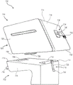
Fig. 7 provides an example vehicle container unit arrangement 700, according to some embodiments of the present disclosure. The vehicle container unit arrangement 700 may include a vehicle container unit 744, one or more features of the vehicle container unit 100 (fig. 1). For example, the vehicle container unit 744 may include the base 702 and the vehicle container 704, where the base 702 may include one or more features of the base 102 (fig. 1) and the vehicle container 704 may include one or more features of the vehicle container 104 (fig. 1). In the illustrated embodiment, the base 702 and the vehicle container 704 are illustrated as being separate prior to mounting the vehicle container 704 to the base 702.
The base 702 may further include a first clamping element 718. A first clamping element 718 may be coupled to the body 706 toward the second end 714 of the body 706. For example, the first clamping element 718 may be coupled at one end to an attachment mechanism of the first mounting plate 712 (e.g., the attachment mechanism 220 (fig. 2)). The first clamping element 718 may include a strap portion 720. The strap portion 720 may comprise a flexible material, such as a flexible plastic or a flexible cloth. The first clamping element 718 may further include a clamping buckle 722. A clip 722 may be coupled to the strap portion 720 at an end of the strap portion 720 opposite the attachment mechanism.
The vehicle container 704 may include a housing 724 having a door 726. Housing 724 may include a mounting element 728 embedded toward a first end 730 of housing 724 and a second mounting plate (e.g., second mounting plate 248 (fig. 2); obscured from view) embedded toward a second end 732 of housing 724. Mounting element 728 may include one or more features of mounting element 242 (fig. 2). The second mounting plate may include one or more features of the second mounting plate 248.
The vehicle container 704 may further include a second clamping element 734. The second clamping element 734 may be coupled to the housing 724 toward the second end 732 of the housing 724. For example, the second clamping element 734 may be coupled to the housing 724 via an attachment plate 736, the attachment plate 736 being embedded within the housing 724 at a side 738 of the housing 724 adjacent the second end 732. The second clamping member 734 may include a strap portion 740. Strap portion 740 may be coupled at one end to attachment plate 736. Band portion 740 may comprise a flexible material, such as a flexible plastic or a flexible cloth. In some embodiments, the strap portion 740 of the second clamping member 734 may comprise the same material as the strap portion 720 of the first clamping member 718. The second clip element 734 may further include a clip 742. A clip 742 may be coupled to the strap portion 740 at an end of the strap portion 720 opposite the attachment plate 736.
The second clamp element 734 may be connected to the first clamp element 718 when the vehicle container 704 is mounted to the base 702. In particular, the clip 742 of the second clip element 734 may be connected to the clip 722 of the first clip element 718. Clip 742 and clip 722 may comprise mating clip clasps. For example, the retaining buckle 742 may comprise a male retaining buckle having a portion that inserts into a female retaining buckle for connection, and the retaining buckle 722 may comprise a female retaining buckle to receive a portion of a male retaining buckle for connection.
Mounting the vehicle container 704 to the base 702 may include a procedure of lowering the vehicle container 704 onto the base 702 such that the mounting elements 728 of the vehicle container 704 are coupled with the attachment elements 708 of the base 702 and the second mounting plate is coupled with the first mounting plate 712 of the base 702. The procedure may include lowering first end 730 of housing 724 onto first end 710 of body 706, with an arm of mounting element 728, such as arm 246 (fig. 2), positioned within a recess of attachment element 708, such as recess 212 (fig. 2), which may include sliding the arm into the recess and moving housing 724 relative to body 706 accordingly. Once the arm has been positioned within the recess, second end 732 of housing 724 may be lowered onto second end 714 of body 706, where second mounting plate is coupled with first mounting plate 712. When the second end 732 of the housing 724 is lowered, the arm may rotate within the recess to be positioned in the coupled position within the recess. After second end 732 of housing 724 has been lowered against second end 714 of body 706, first clamping member 718 may be connected with second clamping member 734 to retain second end 732 of housing 724 against second end 714 of body 706.
The attachment element 708, the first mounting plate 712, and/or the first clamping element 718 may be included in the mounting mechanism of the base 702. Additionally, the mounting element 728, the second mounting plate, and/or the second clamping element 734 may be included in a mounting mechanism of the vehicle pod 704. When the mounting mechanism of the base 702 and the mounting mechanism of the vehicle container 704 are coupled together, the vehicle container 704 may be mounted to the base 702 and may be retained on the base 702.
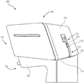
Fig. 8 provides another example vehicle receptacle unit arrangement 800, according to some embodiments of the present disclosure. In particular, the vehicle container unit arrangement 800 illustrates the vehicle container unit 744 of fig. 7. In the illustrated vehicle container unit arrangement 800, a vehicle container 704 is mounted to a base 702.
When the vehicle container 704 is mounted to the base 702, the vehicle container 704 may be positioned on the base 702. As can be seen, when the vehicle container 704 is mounted to the base 702, the first clamp element 718 is connected to the second clamp element 734. In particular, the catch 722 of the first clamping element 718 is connected to the catch 742 of the second clamping element 734. The joined first and second clamp elements 718, 734 may hold the second end 732 of the housing 724 against the second end 714 of the body 706. Retaining second end 732 of housing 724 against second end 714 of body 706 may retain attachment member 708 (fig. 7) in engagement with mounting member 728 (fig. 7) and first mounting plate 712 (fig. 7) in engagement with the second mounting plate to retain mounting of vehicle container 704 to base 702.
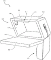
Fig. 9 provides another example vehicle container unit 900 according to some embodiments of the present disclosure. The vehicle container unit 900 may include one or more features of the vehicle container unit 100 (fig. 1). The vehicle container unit 900 may include a base 904 and a vehicle container 906, with the vehicle container 906 shown mounted to the base 904.
The vehicle container unit 900 is illustrated with the door 902 of the vehicle container unit 900 in an open position. For example, the door 902 is shown rotated away from the rest of the housing 908 of the vehicle container 906 via a hinge 910. The hinge 910 can include coupling the door 902 to the housing 908, and the door 902 can rotate about the hinge 910. In some embodiments, hinge 910 may comprise a multi-hinge.
The vehicle container 906 may include a dividing element 912. The separation element 912 may be coupled to an inner wall of an inner wall 914 of the housing 908 via a hinge 916. The separator element 912 can rotate about a hinge 916 between two or more different positions. In some embodiments, the hinge 916 may comprise a multi-hinge. An inner wall 914 of the housing 908 may enclose a space within the housing 908 in which items are to be placed for transport, wherein the inner wall 914 may enclose the space when the door 902 is closed. In the illustrated embodiment, the separation element 912 may be coupled to an inner wall at the top of the housing 908 via a hinge 916.
The separator element 912 may include a wall 918 coupled at one end to the inner wall via a hinge 916. The dividing element 912 may include a handle 920 coupled to the wall 918 and may be used to rotate the wall 918 about a hinge 916. The handle 920 may be coupled to the wall 918 via a hinge (e.g., a multi-hinge). In some embodiments, handle 920 may be omitted.
The separator element 912 can rotate about a hinge 916 between positions. In the illustrated embodiment, the separator element 912 is shown in a first position in which the separator element 912 rotates against an inner wall at the top of the housing 908. The separator element 912 may include a magnet embedded within the wall 918 of the separator element 912 (see fig. 10). When in the first position, the magnets of the separator element 912 may be aligned with magnets embedded within the housing 908, such as the first magnet 266 (fig. 2). The aligned magnets may generate a magnetic force that may hold the separator element 912 in the first position in the absence of an external force. In particular, the separator element 912 may be held in the first position by a magnet until an external force away from the first position exceeds the magnetic force.
Fig. 10 provides another arrangement of the example vehicle container unit 900 of fig. 9 according to some embodiments of the present disclosure. In particular, the separator element 912 of the vehicle container unit 900 is illustrated in a second position where the separator element 912 subdivides the space within the housing 908.
The separation element 912 may include a magnet 1002 embedded within the wall 918. The magnet 1002 may be positioned toward an end of the wall 918 opposite a hinge coupling the wall 918 to an inner wall of the housing 908. When in the second position, the magnet 1002 may be aligned with a magnet embedded within the housing 908, such as the second magnet 268 (fig. 2). The aligned magnets may generate a magnetic force that may hold the separator element 912 in the second position in the absence of an external force. In particular, the separation element 912 may be held in the second position by a magnet until an external force away from the second position exceeds the magnetic force. In other embodiments, magnets embedded within housing 908 may be omitted, and the weight and/or friction between separator element 912 and housing 908 may hold separator element 912 in the second position. While the magnet 1002 and the magnet within the housing 908 are described as magnets, it should be understood that in other embodiments, one or more of the magnets may be replaced by a material (e.g., metal) that the magnet may act on to generate a magnetic force.
In the illustrated embodiment, when in the second position, the handle 920 is rotated against the wall 918. In particular, the handle 920 may be rotated about a hinge coupling the handle 920 to the wall 918 to be positioned against the wall 918. In other cases, the handle 920 may be positioned away from the wall 918. A handle 920 may be used to rotate the wall 918 between the first position and the second position, as well as between other positions. In particular, a user may apply a force to the handle 920 to rotate the wall 918 between different positions. The force applied to handle 920 may exceed the magnetic force generated by the magnet to rotate wall 918 between different positions.
Fig. 11 provides an example vehicle container unit arrangement 1100 according to some embodiments of the present disclosure. In particular, the vehicle container unit arrangement 1100 illustrates a vehicle container unit 1102 mounted on a seat 1104. The vehicle container unit 1102 may include one or more features of the vehicle container unit 100 (fig. 1) and/or the vehicle container unit 900 (fig. 9).
The base 1106 of the vehicle container unit 1102 may be mounted on top of the seat 1104. In particular, a tether of the base 1106 (e.g., tether 500 (fig. 5)) may be connected to one or more anchors of the seat 1104 and mount the base 1106 to the seat 1104. Portions of the base 1106 may extend along a top 1108 of the seat 1104, a front 1110 of the seat 1104, and a back 1112 of the seat 1104. In some embodiments, portions of the base 1106 may be contoured to conform to the top 1108, front 1110, and/or back 1112, respectively, of the seat 1104.
The housing 1114 of the vehicle container unit 1102 may be mounted on top of the base 1106. A portion of the housing 1114 may extend along the back of the seat 1104. In some embodiments, a portion of the housing 1114 may be contoured to conform to the back 1112 of the seat 1104.
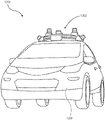
Fig. 12 illustrates an example autonomous vehicle 1200 according to embodiments described herein. An autonomous vehicle 1200 in which a vehicle container unit, such as vehicle container unit 100 (fig. 1), vehicle container unit 744 (fig. 7), vehicle container unit 900 (fig. 9), and/or vehicle container unit 1102 (fig. 11), may be installed. For example, the vehicle receptacle unit may be mounted in a seat in the rear of the autonomous vehicle 1200, and/or in a passenger seat of the autonomous vehicle 1200.
The sensors 1202 may include one or more cameras, one or more LIDAR (light detection and ranging) sensors, one or more radar sensors, or some combination thereof. In some embodiments, the radar sensor may include an articulated radar sensor, a long range radar sensor, a short range radar sensor, or some combination thereof. The sensors 1202 may detect the surroundings of the autonomous vehicle 1200. For example, sensors 1202 may detect one or more objects around autonomous vehicle 1200, such as other cars, pedestrians, trees, bicycles, objects within the road on which autonomous vehicle 1200 is traveling (e.g., buildings and/or other objects that may impede movement of the vehicle), and/or indications around autonomous vehicle 1200 (e.g., building signs, stop signs, and other street signs).
Fig. 13 illustrates an example component 1300 that can be implemented within an autonomous vehicle according to embodiments described herein. In particular, component 1300 may be implemented in an autonomous vehicle such as autonomous vehicle 1200 (fig. 12) as described throughout.
The component 1300 may further include one or more sensors 1304. The sensor 1304 may include one or more features of the sensor 1202. The sensors 1304 may be coupled to the computer 1302, and data captured by the sensors 1304 may be provided to the computer 1302.
The component 1300 may further include one or more vehicle systems 1308. The vehicle system 1308 may be coupled to a computer 1302, and the computer 1302 may control the operation of the vehicle system 1308. The vehicle systems 1308 may include a motion system of an autonomous vehicle, an indicator system of an autonomous vehicle, or some combination thereof. The motion system may include a throttle system, a braking system, a steering system, or some combination thereof, of the autonomous vehicle.
Alternative embodiments
Embodiment 1 may include a base for a vehicle container comprising a body to mount to a vehicle seat, and an attachment element embedded within the body, the attachment element comprising a mounting element to receive a portion of the vehicle container, and wherein the mounting element maintains an upright position of the portion of the vehicle container when received.
Embodiment 3 may include the base of embodiment 2, further comprising a first clamp member coupled at the first end, the first clamp member connected to a second clamp member of the vehicle container, wherein the connected first and second clamp members maintain engagement of the mounting plate of the base and the mounting plate of the vehicle container.
Embodiment 4 may include the base of embodiment 1, wherein a surface of the body to which the vehicle container is to be mounted has a groove, and wherein the attachment element is positioned adjacent to the groove.
Embodiment 5 may include the base of embodiment 1, wherein the attachment member has two holes, wherein the two holes extend through the body from a first surface of the body to which the vehicle container is to be mounted to a second surface of the body to abut the seat, and wherein the two holes have tethers to extend through the two holes and connect to at least one anchor of the seat to mount the base to the seat.
Embodiment 6 may include the base of embodiment 1, wherein the body comprises a foam material, and wherein the attachment member comprises a rigid material.
Embodiment 7 may include the base of embodiment 6, wherein the foam material comprises expanded polypropylene.
Embodiment 8 may include the base of embodiment 6, wherein the rigid material comprises a plastic material.
Embodiment 9 may include a vehicle container unit comprising a vehicle container and a base mounted to a vehicle seat, the vehicle container comprising a housing enclosing a space for carrying items, and a mounting mechanism for mounting the vehicle container, wherein the mounting mechanism comprises an arm, the base comprising a mounting mechanism to couple to the vehicle container, mounting the vehicle container to the base, wherein the mounting mechanism of the base comprises an extension and a recess surrounded by the extension, wherein the arm of the mounting mechanism is positioned in the recess to mount the vehicle container to the base, and wherein the extension maintains a vertical position of the arm when the arm is positioned within the recess.
Example 10 may include the vehicle container unit of example 9, wherein the extension and the recess are positioned toward a first end of the surface of the base, wherein the mounting mechanism of the base further comprises a first clamp element positioned toward a second end of the surface of the base, wherein the arm is positioned toward the first end of the surface of the vehicle container, wherein the mounting mechanism of the vehicle container further comprises a second clamp element positioned toward the second end of the surface of the vehicle container, wherein the first clamp element is connected with the second clamp element, and wherein the first clamp element and the second clamp element, when engaged, retain the second end of the surface of the base against the second end of the surface of the vehicle container.
Embodiment 11 may include the vehicle container unit of embodiment 9, wherein the enclosure includes a door that is rotatable about multiple hinges to open and close the enclosure about the space.
Embodiment 12 may include the vehicle container unit of embodiment 11, further comprising a magnet embedded within the housing, the magnet applying a magnetic force to the door to hold the door in the closed position in the absence of an external force.
Embodiment 13 may include the vehicle container unit of embodiment 9, further comprising a divider member coupled to the housing, the divider member extending within the space and subdividing the space within the housing.
Example 14 may include the vehicle container unit of example 13, wherein the divider member is coupled to the inner wall of the housing via a multi-hinge, the divider member rotating about the multi-hinge between a first position abutting the inner wall and a second position subdividing the space.
Embodiment 15 may include the vehicle container unit of embodiment 9, wherein the outer shell comprises a foam material, and wherein the mounting mechanism of the vehicle container comprises a rigid material.
Example 16 may include the vehicle container unit of example 15, wherein the foam material comprises expanded polypropylene, and wherein the rigid material comprises a plastic material.
Example 17 may include the vehicle container unit of example 9, further comprising a tether, wherein the base further comprises an attachment element having two apertures extending from a first surface of the base to which the vehicle container is to be mounted to a second surface of the base to abut the seat, wherein the tether extends through the two apertures and is connected to an anchoring system of the vehicle seat to mount the base to the seat.
Embodiment 18 may include a vehicle container to be mounted to a base of a vehicle container unit, the vehicle container including a housing enclosing a space for carrying items, an arm at a first end of the housing, wherein the arm is engaged with a mounting element of the base to maintain a vertical position of the first end of the housing when engaged, and a first clamping element at a second end of the housing, the second end opposite the first end, wherein the first clamping element is connected to a second clamping element of the base to maintain the second end of the housing against the base when connected.
Example 19 can include the vehicle container of example 18, further comprising a divider member coupled to the housing via a hinge and positioned within the space enclosed within the housing, wherein the divider member rotates between a first position abutting an inner wall of the housing and a second position subdividing the space.
Embodiment 20 may include the vehicle container of embodiment 18, wherein the outer shell comprises a foam material, and wherein the arm comprises a rigid material.
Other implementation notes, variations, and applications
It is to be understood that not necessarily all objectives or advantages may be achieved in accordance with any particular embodiment described herein. Thus, for example, those skilled in the art will recognize that certain embodiments may be configured to operate in a manner that achieves or optimizes one advantage or group of advantages as taught herein without necessarily achieving other objectives or advantages as may be taught or suggested herein.
In an example embodiment, any number of the circuits in the figures may be implemented on a board of an associated electronic device. The board may be a universal circuit board that may secure various components of the internal electronic system of the electronic device and further provide connectors for other peripheral devices. More specifically, the board may provide an electrical connection through which other components of the system may be in electrical communication. Any suitable processor (including digital signal processors, microprocessors, supporting chipsets, etc.), computer-readable non-transitory memory elements, etc. may be suitably coupled to the board, based on particular configuration needs, processing requirements, computer design, etc. Other components, such as external memory, further sensors, controllers for audio/video display and peripheral devices, may be attached to the board as a plug-in card via a cable, or integrated into the board itself. In various embodiments, the functions described herein may be implemented in an emulated form as software or firmware running within one or more configurable (e.g., programmable) elements arranged in a structure that supports these functions. The software or firmware providing the emulation may be provided on a non-transitory computer readable storage medium containing instructions to allow the processor to perform those functions.
In another example embodiment, the circuitry of the figures may be implemented as a stand-alone module (e.g., a device with associated components and circuitry configured to perform a particular application or function) or as a plug-in module in dedicated hardware of an electronic device. Note that certain embodiments of the present disclosure may be readily included, in part or in whole, in a system-on-chip (SOC) package. An SOC represents an IC that integrates components of a computer or other electronic system into a single chip. It may contain digital, analog, mixed signals, and typically has radio frequency functionality: all of which may be provided on a single chip substrate. Other embodiments may include a multi-chip module (MCM) in which multiple individual ICs are located within a single electronic package and are configured to interact closely with each other through the electronic package. In various other embodiments, the digital filter may be implemented in one or more silicon cores in Application Specific Integrated Circuits (ASICs), field Programmable Gate Arrays (FPGAs), and other semiconductor chips.
It must also be noted that all specifications, dimensions, and relationships outlined herein (e.g., number of processors, logical operations, etc.) are provided for purposes of example and teaching only. Such information may vary considerably without departing from the spirit of the disclosure or the scope of the appended claims. The specifications apply only to one non-limiting example, and therefore, they should be so interpreted. In the foregoing description, example embodiments have been described with reference to particular arrangements of components. Various modifications and changes may be made to such embodiments without departing from the scope of the appended claims. The specification and drawings are, accordingly, to be regarded in an illustrative rather than a restrictive sense.
Note that for the examples provided herein, the interaction may be described in terms of two, three, four, or more electronic components. However, this is done for clarity and example purposes only. It should be appreciated that the system may be incorporated in any suitable manner. Along similar design alternatives, any of the components, modules, and elements illustrated in the figures may be combined in various possible configurations, all of which are clearly within the broad scope of the present disclosure. In some cases, it may be easier to describe one or more functions of a given set of flows by only referencing a limited number of electronic elements. It will be appreciated that the circuits of the figures and their teachings are readily scalable and can accommodate a large number of components, as well as more complex/sophisticated arrangements and configurations. Accordingly, the examples provided should not limit the scope or inhibit the broad teachings of the circuitry potentially applied to myriad other architectures.
It is noted that in the present disclosure, reference to various features (e.g., elements, structures, modules, components, steps, operations, characteristics, etc.) included in "one embodiment", "an example embodiment", "an embodiment", "another embodiment", "some embodiments", "various embodiments", "other embodiments", "alternative embodiments", etc., is intended to mean that any such features are included in one or more embodiments of the present disclosure, but may or may not be combined in the same embodiment.
Numerous other changes, substitutions, variations, alterations, and modifications may be ascertained to one skilled in the art and it is intended that the present disclosure encompass all such changes, substitutions, variations, alterations, and modifications as falling within the scope of the appended claims. Note that all optional features of the above-described apparatus may also be implemented with respect to the methods or processes described herein, and the details in the examples may be used anywhere in one or more embodiments.
Claims (20)
Applications Claiming Priority (3)
| Application Number | Priority Date | Filing Date | Title |
|---|---|---|---|
| US16/731628 | 2019-12-31 | ||
| US16/731,628 US11440478B2 (en) | 2019-12-31 | 2019-12-31 | Interior delivery box |
| PCT/US2020/061701 WO2021137968A1 (en) | 2019-12-31 | 2020-11-22 | Interior delivery box |
Publications (2)
| Publication Number | Publication Date |
|---|---|
| CN115190850A true CN115190850A (en) | 2022-10-14 |
| CN115190850B CN115190850B (en) | 2026-04-28 |
Family
ID=73839107
Family Applications (1)
| Application Number | Title | Priority Date | Filing Date |
|---|---|---|---|
| CN202080097844.6A Active CN115190850B (en) | 2019-12-31 | 2020-11-22 | Internal delivery box |
Country Status (4)
| Country | Link |
|---|---|
| US (2) | US11440478B2 (en) |
| EP (1) | EP4084994B1 (en) |
| CN (1) | CN115190850B (en) |
| WO (1) | WO2021137968A1 (en) |
Families Citing this family (5)
| Publication number | Priority date | Publication date | Assignee | Title |
|---|---|---|---|---|
| KR20220131205A (en) * | 2021-03-19 | 2022-09-27 | 엘지전자 주식회사 | car refrigerator |
| US11833964B2 (en) | 2021-09-30 | 2023-12-05 | Gm Cruise Holdings Llc | Structural base and securement mechanism for an interior delivery container in a vehicle |
| WO2023055452A1 (en) * | 2021-09-30 | 2023-04-06 | Gm Cruise Holdings Llc | Structural base and securement mechanism for an interior delivery container in a vehicle |
| US11787344B2 (en) | 2021-09-30 | 2023-10-17 | Gm Cruise Holdings Llc | Open interior delivery container |
| WO2023055454A1 (en) * | 2021-09-30 | 2023-04-06 | Gm Cruise Holdings Llc | Open interior delivery container |
Citations (10)
| Publication number | Priority date | Publication date | Assignee | Title |
|---|---|---|---|---|
| EP1004475A2 (en) * | 1998-11-24 | 2000-05-31 | PETER BUTZ GmbH & Co Verwaltungs-KG | Device for securing loads in passenger vehicles,such as estate cars, large volume passenger cars or similar |
| NL1017340C1 (en) * | 2001-02-12 | 2002-08-13 | Johannes Wilhelmus Mar Keijser | Device for holding objectss on car seat retains them so that their displacement is prevented by movements of vehicle |
| DE10357356A1 (en) * | 2003-12-09 | 2005-07-07 | Sitech Sitztechnik Gmbh | Object holding device for mounting on the middle armrest of a vehicle seat has fastening brackets with which it is detachably connected to a pivoting middle armrest carrier element |
| WO2005074674A1 (en) * | 2004-02-06 | 2005-08-18 | Cksales Corporation | Pet storage box fixing structure, pet storage box, and connection device |
| JP2005245388A (en) * | 2004-03-08 | 2005-09-15 | Honda Motor Co Ltd | In-vehicle storage container |
| DE102006023948A1 (en) * | 2006-05-17 | 2007-11-22 | Stefanie Schanen | Transport container security system e.g. for passenger and vehicle boots, has a frame with attached snap connector and having bracket arranged to body or seat frame |
| FR2981895A1 (en) * | 2011-10-27 | 2013-05-03 | Renault Sa | STORAGE BOX FOR MOTOR VEHICLE AND AUTOMOTIVE SEAT COMPRISING A BOX |
| US20140263515A1 (en) * | 2013-03-15 | 2014-09-18 | II Thomas W. Cronkright | Equipment cradle for motor vehicles |
| US20190275949A1 (en) * | 2018-03-12 | 2019-09-12 | Honda Motor Co., Ltd. | Apparatus for attaching an accessory to a seat and methods of use thereof |
| US20190352087A1 (en) * | 2018-05-17 | 2019-11-21 | The Boeing Company | Cargo container |
Family Cites Families (5)
| Publication number | Priority date | Publication date | Assignee | Title |
|---|---|---|---|---|
| GB1581535A (en) * | 1972-12-14 | 1980-12-17 | Hambleside Group Ltd | Portable desks |
| US4872723A (en) * | 1988-03-03 | 1989-10-10 | Master Products Inc. | Safety tray |
| GB9418123D0 (en) * | 1994-09-08 | 1994-10-26 | Linnell Michael C | Storage devices |
| US5605389A (en) * | 1994-09-16 | 1997-02-25 | Angeles Group, Inc. | Cabinet, bookcase, locker and cubby structures |
| US10336261B2 (en) * | 2017-05-09 | 2019-07-02 | Ford Global Technologies, Llc | Shelving arrangement for a vehicle |
-
2019
- 2019-12-31 US US16/731,628 patent/US11440478B2/en active Active
-
2020
- 2020-11-22 EP EP20825056.3A patent/EP4084994B1/en active Active
- 2020-11-22 CN CN202080097844.6A patent/CN115190850B/en active Active
- 2020-11-22 WO PCT/US2020/061701 patent/WO2021137968A1/en not_active Ceased
-
2022
- 2022-08-24 US US17/895,043 patent/US11897429B2/en active Active
Patent Citations (10)
| Publication number | Priority date | Publication date | Assignee | Title |
|---|---|---|---|---|
| EP1004475A2 (en) * | 1998-11-24 | 2000-05-31 | PETER BUTZ GmbH & Co Verwaltungs-KG | Device for securing loads in passenger vehicles,such as estate cars, large volume passenger cars or similar |
| NL1017340C1 (en) * | 2001-02-12 | 2002-08-13 | Johannes Wilhelmus Mar Keijser | Device for holding objectss on car seat retains them so that their displacement is prevented by movements of vehicle |
| DE10357356A1 (en) * | 2003-12-09 | 2005-07-07 | Sitech Sitztechnik Gmbh | Object holding device for mounting on the middle armrest of a vehicle seat has fastening brackets with which it is detachably connected to a pivoting middle armrest carrier element |
| WO2005074674A1 (en) * | 2004-02-06 | 2005-08-18 | Cksales Corporation | Pet storage box fixing structure, pet storage box, and connection device |
| JP2005245388A (en) * | 2004-03-08 | 2005-09-15 | Honda Motor Co Ltd | In-vehicle storage container |
| DE102006023948A1 (en) * | 2006-05-17 | 2007-11-22 | Stefanie Schanen | Transport container security system e.g. for passenger and vehicle boots, has a frame with attached snap connector and having bracket arranged to body or seat frame |
| FR2981895A1 (en) * | 2011-10-27 | 2013-05-03 | Renault Sa | STORAGE BOX FOR MOTOR VEHICLE AND AUTOMOTIVE SEAT COMPRISING A BOX |
| US20140263515A1 (en) * | 2013-03-15 | 2014-09-18 | II Thomas W. Cronkright | Equipment cradle for motor vehicles |
| US20190275949A1 (en) * | 2018-03-12 | 2019-09-12 | Honda Motor Co., Ltd. | Apparatus for attaching an accessory to a seat and methods of use thereof |
| US20190352087A1 (en) * | 2018-05-17 | 2019-11-21 | The Boeing Company | Cargo container |
Also Published As
| Publication number | Publication date |
|---|---|
| EP4084994A1 (en) | 2022-11-09 |
| EP4084994B1 (en) | 2026-01-07 |
| US20210197727A1 (en) | 2021-07-01 |
| US11897429B2 (en) | 2024-02-13 |
| CN115190850B (en) | 2026-04-28 |
| US11440478B2 (en) | 2022-09-13 |
| WO2021137968A1 (en) | 2021-07-08 |
| US20220402437A1 (en) | 2022-12-22 |
Similar Documents
| Publication | Publication Date | Title |
|---|---|---|
| CN115190850B (en) | Internal delivery box | |
| US6685016B2 (en) | Entertainment system comprising suspension platform | |
| US12157533B2 (en) | Micro-mobility fleet vehicle cockpit assembly systems and methods | |
| US6283299B1 (en) | Compartmentalized carrier and presentation bag for portable TV and video media player | |
| US11077767B2 (en) | Vehicle battery integration systems and methods | |
| KR20210062684A (en) | Detachable Vehicle LIDAR Data Acquisition Pod | |
| US12030391B2 (en) | Modular bicycle designs | |
| JP6536531B2 (en) | Vehicle information terminal | |
| US20120255982A1 (en) | Dean's easy Hold GPS Mount | |
| US20040112931A1 (en) | Entertainment system comprising suspension platform | |
| US20210402885A1 (en) | Micromobility transit vehicle battery charging systems and methods | |
| CN105163984A (en) | Pivotable vehicle mount for mobile computing devices | |
| US12377736B2 (en) | Vehicle battery integration systems and methods | |
| EP1504239A2 (en) | Method and device for a detachable navigation system | |
| US11833964B2 (en) | Structural base and securement mechanism for an interior delivery container in a vehicle | |
| CN104736458A (en) | Sensor pod | |
| EP2744687A1 (en) | Double din automobile mount for tablet computers | |
| US12269549B2 (en) | Vehicle seat adjustment and securing systems and methods | |
| US12183935B2 (en) | Vehicle battery securing systems and methods | |
| US12245408B2 (en) | Motor controller heat dissipating systems and methods | |
| JP2003309410A (en) | Mounting structure of embedded antenna for vehicle and mounting method of embedded antenna for vehicle | |
| CN104586097A (en) | Vehicle-mounted express delivery piece dispatching device with rotational symmetrical storage cabinet structure | |
| CN110239447A (en) | One cartridge and unmanned vehicle | |
| JP2006062399A (en) | Portable personal computer locking structure | |
| JPH09329448A (en) | Navigation device |
Legal Events
| Date | Code | Title | Description |
|---|---|---|---|
| PB01 | Publication | ||
| PB01 | Publication | ||
| SE01 | Entry into force of request for substantive examination | ||
| SE01 | Entry into force of request for substantive examination | ||
| GR01 | Patent grant |