EP1004475A2 - Device for securing loads in passenger vehicles,such as estate cars, large volume passenger cars or similar - Google Patents
Device for securing loads in passenger vehicles,such as estate cars, large volume passenger cars or similar Download PDFInfo
- Publication number
- EP1004475A2 EP1004475A2 EP99117509A EP99117509A EP1004475A2 EP 1004475 A2 EP1004475 A2 EP 1004475A2 EP 99117509 A EP99117509 A EP 99117509A EP 99117509 A EP99117509 A EP 99117509A EP 1004475 A2 EP1004475 A2 EP 1004475A2
- Authority
- EP
- European Patent Office
- Prior art keywords
- vehicle
- locking elements
- elements
- locking
- counter
- Prior art date
- Legal status (The legal status is an assumption and is not a legal conclusion. Google has not performed a legal analysis and makes no representation as to the accuracy of the status listed.)
- Granted
Links
- 238000009434 installation Methods 0.000 claims description 18
- 239000000969 carrier Substances 0.000 claims 3
- 230000006835 compression Effects 0.000 description 2
- 238000007906 compression Methods 0.000 description 2
- 230000037431 insertion Effects 0.000 description 2
- 238000003780 insertion Methods 0.000 description 2
- 239000011159 matrix material Substances 0.000 description 2
- 230000000712 assembly Effects 0.000 description 1
- 238000000429 assembly Methods 0.000 description 1
- 238000006073 displacement reaction Methods 0.000 description 1
- 230000003993 interaction Effects 0.000 description 1
- 238000004519 manufacturing process Methods 0.000 description 1
- 239000002184 metal Substances 0.000 description 1
Images


Classifications
-
- B—PERFORMING OPERATIONS; TRANSPORTING
- B60—VEHICLES IN GENERAL
- B60R—VEHICLES, VEHICLE FITTINGS, OR VEHICLE PARTS, NOT OTHERWISE PROVIDED FOR
- B60R5/00—Compartments within vehicle body primarily intended or sufficiently spacious for trunks, suit-cases, or the like
-
- B—PERFORMING OPERATIONS; TRANSPORTING
- B60—VEHICLES IN GENERAL
- B60R—VEHICLES, VEHICLE FITTINGS, OR VEHICLE PARTS, NOT OTHERWISE PROVIDED FOR
- B60R7/00—Stowing or holding appliances inside vehicle primarily intended for personal property smaller than suit-cases, e.g. travelling articles, or maps
- B60R7/04—Stowing or holding appliances inside vehicle primarily intended for personal property smaller than suit-cases, e.g. travelling articles, or maps in driver or passenger space, e.g. using racks
- B60R7/043—Stowing or holding appliances inside vehicle primarily intended for personal property smaller than suit-cases, e.g. travelling articles, or maps in driver or passenger space, e.g. using racks mounted on or under a seat
Definitions
- the invention relates to a load securing device for passenger cars, like for combination cars, Greater sedans or the like. according to the respective generic term of the subordinate claims 1, 2 and 3.
- a load securing device has become known from DE 195 13 215 C1.
- the known load securing device has a modular surface element, which on the Back one from an upright position into one about horizontal position hinged rear seat back attached is.
- the one that forms a clamping plate modular surface element four toggle screws (counter element elements on the surface element side), which with mounting holes (locking elements on the vehicle) the rear seat back interact so that the load securing device quickly assembled if necessary and can be dismantled just as quickly.
- the detachable locking connection between the vehicle-side locking elements and the surface element side Counter-locking elements pioneering holding surface of the known modular fastener element can be a Vehicle equipment part of different types, see above e.g. an erectable metal grille or one Belt lashing device for holding elongated Carry loads (e.g. skis).
- DE-GM 93 11 587 is a load securing device with in the hold of a combination car fixed at one end, overlapping the load Lashing straps described, the free ends, comparable with seat belts, male-like connectors (Counter-locking elements), which with vehicle-side matrix or sleeve-like locking elements a releasable Make a latching connection.
- DE-GM 297 11 198 is one to one another type of transport container device (Ski bag device) became known, the vehicle side frame-like fastening arrangement a frame-shaped Plant-holding surface forms on which instead of Holding frame of a ski bag using an adapter plate at least one latch can be attached.
- the Adapter plate can, for example, on the trunk side or a cool box or another in the passenger compartment Attach any transport container.
- the Obtain adapter plate according to DE-GM 297 11 198 be that one and the same adapter plate optional and interchangeable a variety of different transport containers can record. In such a case in the known adapter plate the attachment points by detachable fasteners, in particular by screw fasteners or by Bayonet-like fasteners.
- the task is based on the known load securing device so that this not just for use with rear seat backrests but is more universal than before.
- one is the number of the counter-locking elements, a different one Arrangement of the modular surface element, Number of locking elements on the vehicle of the same type and / or on different types of vehicle Installation fields available, the vehicle-side Locking elements as well as the counter locking elements in arranged in a certain uniform grid division are.
- the essence of the invention according to the claim 1 is that not just for example Similar installation areas on the vehicle, so not just on the backs of backrests, but practically on all suitable, mutually different Position the vehicle on-board locking elements can be provided.
- the vehicle on-board locking elements For example in the vehicle floor or in the cargo area floor on the vehicle side Locking elements must be installed. All on-board Locking elements are in a certain uniform Grid division, for example on the corners a square with a side length of 5 cm.
- a modular type according to the invention Surface element which has vehicle equipment parts on its holding surface or assemblies of the most varied Kind can carry practically anywhere in the Vehicle releasably attached.
- one is the number of the counter-locking elements, a different one Arrangement of the modular surface element, Number of locking elements on the vehicle of the same type and / or on different types of vehicle Installation fields available, the vehicle-side Locking elements as well as the counter-locking elements arranged in a certain uniform grid division are, and that the holding surface of the modular Area element in a certain uniform Has grid locking elements arranged, which with uniform determined in the same Grid spacing arranged counter holding elements at least a detachable part of a vehicle Form retaining snap connection.
- the solution according to the invention according to the claim 3 represents a combination of the objects of the Claims 1 and 2, which results in a particularly advantageous results in universal applicability.
- the vehicle-side locking elements a consistently uniform Grid, which advantageously a optional offset arrangement of the modular surface element by one grid division or by several grid divisions allowed.
- the invention provides that the vehicle side Locking elements in different vehicle-side Installation areas are arranged. So it offers Possibility of locking elements on the vehicle e.g. to the rear seat back surfaces or on the vehicle or to be placed on the load floor.
- Another variant of the invention is by a Number of counter holding elements exceeding number characterized by locking elements on the surface element side.
- This variant of the invention allows the possibility e.g. smaller ones provided with counter-locking elements Vehicle equipment parts on the with the Retaining latch elements provided surface element side Arrange the stopping surface optionally.
- a flush fit for practical use Installation position is according to other features of the invention given that the vehicle-side locking elements in the floor area of a recess on the vehicle are arranged to meet the space requirements of the modular Area element is adapted.
- Another embodiment of the invention provides that vehicle-side locking elements and corresponding Counter catch elements on the surface element side, on the one hand and Retaining elements on the surface element side and corresponding ones Bracket locking elements of the vehicle equipment part on the other hand different from each other are trained.
- the invention in this context also includes such positive locking elements, which are not resistant to tensile and compression can be locked, but which is a fuse represent against displacement and / or against rotation can.
- An advantageous embodiment according to the invention of locking connections is that the locking connection and / or the holding latch connection at least one each male-like and at least one corresponding one have matrix-like locking element.
- a locking of the locking elements can be according to the invention are designed so that the patrician Locking elements each have at least one locking recess have, each with at least a movable in the matrix-like locking element Latch locking and unlocking interacts.
- a locking between locking elements advantageously be such that the locking recess of each male-like Locking element a limiting its outer circumference, ring groove open to the outside, which each of a translationally movable fork-shaped Bolt is gripped.
- a user-friendly actuation of the lock according to the invention is that all single ledger led together on the die side can be handled by means of an actuating element.
- FIG. 3 shows the essential components a load securing device, designated overall by 10 seen overall.
- To load securing device 10 include In the present case, similar installation areas on the vehicle G on the rear back surfaces 11 of rear seat backrests 12 three rear seats 13.
- the rear seat backrests 12 each have on their rear back surfaces 11 a recess 14, in each of which approximately plate-shaped modular surface element 15 Recorded flush to the rear back surface 11 can be.
- each recess 14 In the bottom surface 16 of each recess 14 are four matrix-like locking elements on the vehicle 17 embedded, in which four locking pins (male-shaped counter-locking elements) 18 locked and can intervene easily.
- the direction of insertion is marked with y.
- the surface of the module-like element facing away from the elements 17, 18 Surface element 15, the holding surface, is with H denotes.
- the holding surface H has four matrix-like Retaining latch elements 19, in which pin-shaped Retaining latch elements 20 introduced locking can be. In this case, too Entry direction marked with y.
- the counter holding elements 20 are one on the bottom and schematically represented as a base plate vehicle equipment parts 21 arranged.
- the grid divisions of the vehicle-side die-shaped Locking elements 17, the counter-locking elements (Locking pin) 18, the holding locking elements 19 and the counter holding locking elements 20 are identical.
- Fig. 1 So is in Fig. 1 as a vehicle equipment part Shown container 21, which is analogous to that in Fig. 3 shown with a mounting area G of the rear Backrest surface 11 in the direction of travel x the front seat back 12 folded is locked.
- matrix-like locking elements 17 On the floor 22 of the combination motor vehicle are a number of matrix-like locking elements 17 marked with crosses. This locking elements 17th compared to those of the backrest surface 11 a dissimilar installation area on the vehicle U represents.
- matrix-shaped Locking elements 17 In four of a plate-shaped module-like surface element 15 covered matrix-shaped Locking elements 17 are the counter-locking elements, not shown (Locking pin) 18 of the modular Surface element 15 inserted and locked.
- the modular surface element 15 faces upwards open retaining latch elements 19 for receiving not shown Counter holding elements 20 of a vehicle equipment part on.
- the locking elements of the modular Surface elements 15 are common by means of an actuating handle B operable.
- FIG. 2 is intended to show that that releasably attached to the rear back surface 11 modular surface element 15 an upper part TO and has a lower part TU. Both parts TO and TU are pivoted to one another via a hinge axis S, so that the upper part TO compensate for the inclination the folded rear seat back 12 can be pivoted can to the holding surface H in a horizontal position to move.
- the parts TO and TU are not shown Locking means in a desired inclination lockable.
- FIG. 4 is the vehicle equipment part from a two loading openings 23, 24 Vehicle equipment part 21 in the form of a ski bag holder.
- the ski bag 25 is in the open, open operating position shown.
- the fork holder 21 carries the holding surface H of the modular Surface element 15 as a vehicle equipment part 21 each a fork holder for a bicycle front fork 26.
- the fork holder 21 have in, not shown Way downward protruding locking elements (Pin) 20, which with the retaining latching elements 19 of the Interact holding surface H of the modular surface element 15.
- Pin Way downward protruding locking elements
- the fork holder 21 in one piece with the modular surface element 15 on the Arrange holding surface H.
- the vehicle equipment part 21 formed by a foldable ski grab bar.
- the end of the ski holding bracket 21 projects downwards Counter holding element (pin) 20, which with each a matrix-shaped retaining latch element 19 of the holding surface H cooperates.
- the plate-shaped module-like surface element 15 has four matrix-like retaining catch elements 19, in which pin-like counter-locking elements 20 of a vehicle equipment part 21 (here as floor element only shown as pars pro toto) in the direction of insertion y can be used.
- the essentially rotationally symmetrical pin 20 each have one extending outwardly over the circumference Ring groove 27, each of which is forked trained latch 28 is encompassed.
- each fork 28 has an inner locking edge 29 and one outer locking edge 30. In this way, the Forks 28 in the same locking direction a together lock and in the same unlocking direction c unlock together.
- dumbbell-shaped components 32 can by means of the actuating handle B via its driver webs 33 can be operated using the same movement. This is done the unlocking stroke in direction c against the Restoring force of the two helical compression springs 34.
Landscapes
- Engineering & Computer Science (AREA)
- Mechanical Engineering (AREA)
- Seats For Vehicles (AREA)
- Vehicle Step Arrangements And Article Storage (AREA)
- Connection Of Plates (AREA)
- Fittings On The Vehicle Exterior For Carrying Loads, And Devices For Holding Or Mounting Articles (AREA)
Abstract
Description
Die Erfindung betrifft eine Ladungssicherungsvorrichtung
für Personenkraftwagen, wie für Kombinationskraftwagen,
Großraumlimousinen od.dgl. entsprechend dem
jeweiligen Oberbegriff der einander nebengeordneten Ansprüche
1, 2 und 3. Eine solche Ladungssicherungsvorrichtung
ist durch die DE 195 13 215 C1 bekanntgeworden.The invention relates to a load securing device
for passenger cars, like for combination cars,
Greater sedans or the like. according to the
respective generic term of the
Die bekannte Ladungssicherungsvorrichtung weist ein modulartiges Flächenelement auf, welches an der Rückseite einer von einer aufrechten Position in eine etwa horizontale Position klappbaren Rücksitzlehne befestigt ist. Hierzu weist das eine Aufspannplatte bildende modulare Flächenelement vier Knebelschrauben (flächenelementseitige Gegenrastelemente) auf, welche mit Halterungslöchern (fahrzeugseitige Rastelemente) der Rücksitzlehne derart zusammenwirken, daß die Ladungssicherungsvorrichtung im Bedarfsfall rasch montiert und ebenso rasch wieder demontiert werden kann.The known load securing device has a modular surface element, which on the Back one from an upright position into one about horizontal position hinged rear seat back attached is. For this purpose, the one that forms a clamping plate modular surface element four toggle screws (counter element elements on the surface element side), which with mounting holes (locking elements on the vehicle) the rear seat back interact so that the load securing device quickly assembled if necessary and can be dismantled just as quickly.
Die von der lösbaren Rastverbindung zwischen den fahrzeugseitigen Rastelementen und den flächenelementseitigen Gegenrastelementen wegweisende Haltefläche des bekannten modulartigen Bafestigungselements kann ein Fahrzeug-Ausstattungsteil unterschiedlicher Art, so z.B. ein aufrichtbares Metall-Schutzgitter oder eine Gurt-Verzurrvorrichtung zur Halterung langgestreckten Ladeguts (z.B. Skier), tragen.The detachable locking connection between the vehicle-side locking elements and the surface element side Counter-locking elements pioneering holding surface of the known modular fastener element can be a Vehicle equipment part of different types, see above e.g. an erectable metal grille or one Belt lashing device for holding elongated Carry loads (e.g. skis).
Im DE-GM 93 11 587 ist eine Ladungssicherungsvorrichtung mit in dem Laderaum eines Kombinationskraftwagens einendig befestigten, das Ladegut Übergreifenden Verzurrgurten beschrieben, deren freie Enden, vergleichbar mit Sicherheitsgurten, patrizenartige Stecker (Gegenrastelemente) tragen, welche mit fahrzeugseitigen matrizen- bzw. hülsenartigen Rastelementen eine lösbare Rastverbindung eingehen.In DE-GM 93 11 587 is a load securing device with in the hold of a combination car fixed at one end, overlapping the load Lashing straps described, the free ends, comparable with seat belts, male-like connectors (Counter-locking elements), which with vehicle-side matrix or sleeve-like locking elements a releasable Make a latching connection.
Durch das DE-GM 297 11 198 ist eine zu einer anderen Gattung zählende Transportbehälter-Einrichtung (Skisack-Einrichtung) bekanntgeworden, deren fahrzeugseitige zargenartige Befestigungsanordnung eine rahmenförmige Anlage-Haltefläche bildet, an welcher statt des Halterahmens eines Skisacks eine Adapterplatte mittels mindestens eines Riegels befestigt werden kann. An der Adapterplatte läßt sich beispielsweise kofferraumseitig oder in der Fahrgastzelle eine Kühlbox oder ein anderer beliebiger Transportbehälter anbringen. Dabei kann die Adapterplatte gemäß dem DE-GM 297 11 198 so beschaffen sein, daß ein und dieselbe Adapterplatte wahlweise und austauschbar eine Vielzahl unterschiedlicher Transportbehälter aufnehmen kann. In einem solchen Falle sind bei der bekannten Adapterplatte die Befestigungsstellen durch voneinander lösbare Befestigungselemente, insbesondere durch Schraubbefestigungselemente oder durch bajonettähnliche Befestigungselemente, gebildet. DE-GM 297 11 198 is one to one another type of transport container device (Ski bag device) became known, the vehicle side frame-like fastening arrangement a frame-shaped Plant-holding surface forms on which instead of Holding frame of a ski bag using an adapter plate at least one latch can be attached. At the Adapter plate can, for example, on the trunk side or a cool box or another in the passenger compartment Attach any transport container. The Obtain adapter plate according to DE-GM 297 11 198 be that one and the same adapter plate optional and interchangeable a variety of different transport containers can record. In such a case in the known adapter plate the attachment points by detachable fasteners, in particular by screw fasteners or by Bayonet-like fasteners.
Ausgehend von der bekannten Ladungssicherungsvorrichtung
gemäß der DE 195 13 215 C1, liegt der Erfindung
die Aufgabe zugrunde, die bekannte Ladungssicherungsvorrichtung
so weiterzubilden, daß diese
nicht nur auf die Verwendung bei Rücksitzlehnen sondern
universeller als bisher einsetzbar ist. Gemeinsam mit
den Merkmalen des Oberbegriffs des Anspruchs 1 wird
diese Aufgabe entsprechend der Erfindung mit den Merkmalen
des jeweiligen Kennzeichenteil der Ansprüche 1, 2
oder 3 gelöst.Starting from the known load securing device
according to DE 195 13 215 C1, the invention
the task is based on the known load securing device
so that this
not just for use with rear seat backrests but
is more universal than before. Together with
the features of the preamble of
Entsprechend dem Anspruch 1 ist eine die Anzahl
der Gegenrastelemente übersteigende, eine unterschiedliche
Anordnung des modulartigen Flächenelements gestattende,
Anzahl von fahrzeugseitigen Rastelementen an
gleichartigen und/oder an ungleichartigen fahrzeugseitigen
Einbaufeldern vorhanden, wobei die fahrzeugseitigen
Rastelemente ebenso wie die Gegenrastelemente in
einer bestimmten einheitlichen Rasterteilung angeordnet
sind.According to
Das Wesen der Erfindung entsprechend dem Anspruch
1 besteht darin, daß nicht nur beispielsweise an
gleichartigen fahrzeugseitigen Einbaufeldern, also
nicht nur an den Rückseiten von Rückenlehnen, sondern
praktisch an allen geeigneten, untereinander ungleichartigen
Stellen des Fahrzeugs fahrzeugseitige Rastelemente
vorgesehen sein können. So können beispielsweise
in den Fahrzeugboden bzw. in den Laderaumboden fahrzeugseitige
Rastelemente eingebaut sein. Alle fahrzeugseitigen
Rastelemente sind in einer bestimmten einheitlichen
Rasterteilung, beispielsweise auf den Ecken
eines Quadrats mit 5 cm Seitenlänge, angeordnet. Auf
diese Weise kann ein erfindungsgemäßes modulartiges
Flächenelement, welches an seiner Haltefläche Fahrzeug-Ausstattungsteile
bzw. Baugruppen unterschiedlichster
Art tragen kann, praktisch an beliebigen Stellen des
Fahrzeugs lösbar befestigt sein.The essence of the invention according to the
Gemäß Anspruch 2 weist die Haltefläche des modulartigen
Flächenelements in einer bestimmten einheitlichen
Rasterteilung angeordnete Halterastelemente auf,
welche mit in derselben bestimmten einheitlichen
Rasterteilung angeordneten Gegenhalterastelementen mindestens
eines Fahrzeug-Ausstattungsteils eine lösbare
Halterastverbindung bilden.According to
Entsprechend den vorstehenden Erfindungsmerkmalen weisen sowohl die Haltefläche des modulartigen Flächenelements als auch x-beliebige Fahrzeug-Ausstattungsteile miteinander kompatible Halte- und Gegenhalterastelemente mit derselben einheitlichen Rasterteilung auf. Auf diese Weise können mit der Haltefläche des erfindungsgemäßen modulartigen Flächenelements, bezogen entweder auf ein bestimmtes fahrzeugseitiges Einbaufeld oder bezogen auf gleichartige bzw. ungleichartige fahrzeugseitige Einbaufelder, in wechselnder Zuordnung Fahrzeugausstattungsteile unterschiedlicher Art verbunden werden.According to the above features of the invention have both the holding surface of the modular surface element as well as any vehicle equipment parts mutually compatible holding and counter holding elements with the same uniform grid division. In this way, with the holding surface of the invention modular surface element, related either to a specific installation area on the vehicle or related to similar or dissimilar vehicle-side Installation fields, in changing assignment Vehicle equipment parts of different types connected become.
Entsprechend dem Anspruch 3 ist eine die Anzahl der Gegenrastelemente übersteigende, eine unterschiedliche Anordnung des modulartigen Flächenelements gestattende, Anzahl von fahrzeugseitigen Rastelementen an gleichartigen und/oder an ungleichartigen fahrzeugseitigen Einbaufeldern vorhanden, wobei die fahrzeugseitigen Rastelemente ebenso wie die Gegenrastelemente in einer bestimmten einheitlichen Rasterteilung angeordnet sind, und daß die Haltefläche des modulartigen Flächenelements in einer bestimmten einheitlichen Rasterteilung angeordnete Halterastelemente aufweist, welche mit in derselben bestimmten einheitlichen Rasterteilung angeordneten Gegenhalterastelementen mindestens eines Fahrzeug-Ausstattungsteils eine lösbare Halterastverbindung bilden.According to claim 3, one is the number of the counter-locking elements, a different one Arrangement of the modular surface element, Number of locking elements on the vehicle of the same type and / or on different types of vehicle Installation fields available, the vehicle-side Locking elements as well as the counter-locking elements arranged in a certain uniform grid division are, and that the holding surface of the modular Area element in a certain uniform Has grid locking elements arranged, which with uniform determined in the same Grid spacing arranged counter holding elements at least a detachable part of a vehicle Form retaining snap connection.
Die erfindungsgemäße Lösung entsprechend dem Anspruch
3 stellt eine Kombination der Gegenstände der
Ansprüche 1 und 2 dar, woraus sich eine besonders vorteilhafte
universelle Anwendbarkeit ergibt.The solution according to the invention according to the claim
3 represents a combination of the objects of the
In weiterer Ausgestaltung der Erfindung bilden die fahrzeugseitigen Rastelemente ein durchgehend einheitliches Rasterfeld, welches in vorteilhafter Weise eine wahlfreie versetzte Anordnung des modulartigen Flächenelements um eine Rasterteilung oder um mehrere Rasterteilungen gestattet.In a further embodiment of the invention, the vehicle-side locking elements a consistently uniform Grid, which advantageously a optional offset arrangement of the modular surface element by one grid division or by several grid divisions allowed.
Weiterhin sieht die Erfindung vor, daß fahrzeugseitige Rastelemente in unterschiedlichen fahrzeugseitigen Einbaufeldern angeordnet sind. So bietet sich die Möglichkeit, fahrzeugseitige Rastelemente z.B. an den rückwärtigen Sitzlehnenflächen oder auf dem Fahrzeug- bzw. auf dem Laderaumboden anzuordnen. Furthermore, the invention provides that the vehicle side Locking elements in different vehicle-side Installation areas are arranged. So it offers Possibility of locking elements on the vehicle e.g. to the rear seat back surfaces or on the vehicle or to be placed on the load floor.
Eine andere Erfindungsvariante ist durch eine die Anzahl der Gegenhalterastelemente übersteigende Anzahl von flächenelementseitigen Rastelementen gekennzeichnet. Diese Erfindungsvariante gestattet die Möglichkeit, z.B. mit Gegenrasthalteelementen versehene kleinere Fahrzeug-Ausstattungsteile auf der mit den Halterastelementen versehenen flächenelementseitigen Haltefläche wahlfrei versetzt anzuordnen.Another variant of the invention is by a Number of counter holding elements exceeding number characterized by locking elements on the surface element side. This variant of the invention allows the possibility e.g. smaller ones provided with counter-locking elements Vehicle equipment parts on the with the Retaining latch elements provided surface element side Arrange the stopping surface optionally.
Eine Vereinfachung der Fertigung und gegebenenfalls zusätzliche Variationsmöglichkeiten lassen sich dann erzielen, wenn in weiterer Ausgestaltung der Erfindung die Rasterteilung von fahrzeugseitigen Rastelementen einschließlich korrespondierender flächenelementseitiger Gegenrastelemente sowie von flächenelementseitigen Halterastelementen einschließlich korrespondierender Gegenhalterastelemente des Fahrzeug-Ausstattungsteils dieselbe ist.A simplification of production and, if necessary additional variation options can be then achieve if in a further embodiment of the invention the grid division of vehicle-side locking elements including corresponding surface element side Counter-locking elements as well as surface-side elements Retaining catch elements including corresponding Bracket locking elements of the vehicle equipment part is the same.
Für den Fall, daß das fahrzeugseitige Einbaufeld zur Anbringung des modulartigen Flächenelements nur eine ungünstige Einbaulage darbietet, ist entsprechend der Erfindung eine Anpassungsmöglichkeit dadurch gegeben, daß die Haltefläche des modulartigen Flächenelements bezüglich der flächenelementseitigen Gegenrastelemente lageveränderbar, z.B. neigungsveränderbar od.dgl., ausgebildet ist.In the event that the vehicle-side installation field to attach the modular surface element only an unfavorable installation position is appropriate given the invention an adaptability by that the holding surface of the modular surface element with regard to the counter-locking elements on the surface element side changeable, e.g. inclination changeable or the like, is formed.
Eine dem praktischen Gebrauch angepaßte bündige Einbaulage ist entsprechend anderen Erfindungsmerkmalen dadurch gegeben, daß die fahrzeugseitigen Rastelemente in der Bodenfläche einer fahrzeugseitigen Aussparung angeordnet sind, die an den Raumbedarf des modulartigen Flächenelements angepaßt ist.A flush fit for practical use Installation position is according to other features of the invention given that the vehicle-side locking elements in the floor area of a recess on the vehicle are arranged to meet the space requirements of the modular Area element is adapted.
Eine andere Ausgestaltung der Erfindung sieht vor, daß fahrzeugseitige Rastelemente und korrespondierende flächenelementseitige Gegenrastelemente einerseits und flächenelementseitige Halterastelemente und korrespondierende Gegenhalterastelemente des Fahrzeug-Ausstattungsteils andererseits untereinander jeweils unterschiedlich ausgebildet sind. Dies bedeutet, daß z.B. nicht alle Rastelement-Paare patrizen- und matrizenförmig geformt sein müssen. Vielmehr kann es auch genügen, patrizen- und matrizenartige Rastelement-Paare mit anderen Formschlußelement-Paaren, wie z.B. Rippen und Nuten, zu kombinieren. Unter Rastelementen versteht die Erfindung in diesem Zusammenhang auch solche Formschlußelemente, die zwar nicht zug- und druckfest ineinander verriegelbar sind, welche jedoch eine Sicherung gegen Verschiebung und/oder gegen Verdrehung darstellen können.Another embodiment of the invention provides that vehicle-side locking elements and corresponding Counter catch elements on the surface element side, on the one hand and Retaining elements on the surface element side and corresponding ones Bracket locking elements of the vehicle equipment part on the other hand different from each other are trained. This means that e.g. not all locking element pairs are male and female have to be shaped. Rather, it can sufficient, male and female locking element pairs with other form-locking element pairs, e.g. Ribs and grooves to combine. Under locking elements understood the invention in this context also includes such positive locking elements, which are not resistant to tensile and compression can be locked, but which is a fuse represent against displacement and / or against rotation can.
Eine vorteilhafte erfindungsgemäße Ausführungsform von Rastverbindungen besteht darin, daß die Rastverbindung und/oder die Halterastverbindung je mindestens ein patrizenartiges und je mindestens ein korrespondierendes matrizenartiges Rastelement aufweisen.An advantageous embodiment according to the invention of locking connections is that the locking connection and / or the holding latch connection at least one each male-like and at least one corresponding one have matrix-like locking element.
Eine Verriegelung der Rastelemente kann erfindungsgemäß so ausgeführt werden, daß die patrizenartigen Rastelemente jeweils mindestens eine Verriegelungsaussparung aufweisen, welche jeweils mit mindestens einem im matrizenartigen Rastelement geführten beweglichen Riegel verriegelnd und entriegelnd zusammenwirkt.A locking of the locking elements can be according to the invention are designed so that the patrician Locking elements each have at least one locking recess have, each with at least a movable in the matrix-like locking element Latch locking and unlocking interacts.
Im einzelnen kann eine Verriegelung zwischen Rastelementen in vorteilhafter Weise so beschaffen sein, daß die Verriegelungsaussparung eines jeden patrizenartigen Rastelements eine dessen Außenumfang begrenzende, nach außen offene Ringnut bildet, welche jeweils von einem translatorisch verschieblichen gabelförmig ausgebildeten Riegel umgriffen ist.In particular, a locking between locking elements advantageously be such that the locking recess of each male-like Locking element a limiting its outer circumference, ring groove open to the outside, which each of a translationally movable fork-shaped Bolt is gripped.
Eine bedienungsfreundliche Betätigung der Verriegelung besteht erfindungsgemäß darin, daß alle matrizenseitig geführten einzelnen Riegel gemeinsam mittels eines Betätigungselements handhabbar sind.A user-friendly actuation of the lock according to the invention is that all single ledger led together on the die side can be handled by means of an actuating element.
In den Zeichnungen ist die Erfindung anhand bevorzugter
Ausführungsbeispiele im wesentlichen schematisch
dargestellt, es zeigt,
Aus Fig. 3 sind die wesentlichen Bestandteile einer insgesamt mit 10 bezeichneten Ladungssicherungsvorrichtung insgesamt zu ersehen.3 shows the essential components a load securing device, designated overall by 10 seen overall.
Zur Ladungssicherungsvorrichtung 10 gehören im
vorliegenden Falle gleichartige fahrzeugseitige Einbaufelder
G an den rückwärtigen Lehnenflächen 11 von Fondsitzlehnen
12 dreier Fondsitze 13. Die Fondsitzlehnen
12 weisen an ihren rückwärtigen Lehnenflächen 11 jeweils
eine Aussparung 14 auf, in welcher jeweils ein
etwa plattenförmiges modulartiges Flächenelement 15
flächenbündig zur rückwärtigen Lehnenfläche 11 aufgenommen
werden kann. To load securing
In die Bodenfläche 16 einer jeden Aussparung 14
sind vier matrizenartige fahrzeugseitige Rastelemente
17 eingelassen, in welche vier Rastzapfen
(patrizenförmige Gegenrastelemente) 18 verriegelt und
leicht lösbar eingreifen können. Die Einführrichtung
ist mit y gekennzeichnet.In the
Die den Elementen 17, 18 abgewandte Fläche des modulartigen
Flächenelements 15, die Haltefläche, ist mit
H bezeichnet. Die Haltefläche H weist vier matrizenartige
Halterastelemente 19 auf, in welche zapfenförmige
Gegenhalterastelemente 20 verriegelnd eingeführt
werden können. Auch in diesem Falle ist die jeweilige
Einführrichtung mit y gekennzeichnet. Die Gegenhalterastelemente
20 sind bodenseitig eines insgesamt
und schematisch als Bodenplatte dargestellten Fahrzeug-Ausstattungsteile
21 angeordnet.The surface of the module-like element facing away from the
Die Rasterteilungen der fahrzeugseitigen matrizenförmigen
Rastelemente 17, der Gegenrastelemente
(Rastzapfen) 18, der Halterastelemente 19 und der Gegenhalterastelemente
20 sind jeweils identisch.The grid divisions of the vehicle-side die-
Aus Fig. 3 wird deutlich, daß das modulartige
Flächenelement 15 wahlweise in eines der drei sitzlehnenseitigen
gleichartigen Einbaufelder G eingesetzt
werden kann. Ebensogut ist es möglich, zugleich in
jedes der Einbaufelder G je ein modulartiges Flächenelement
15 einzusetzen. Mit jedem modulartigen Flächenelement
15 kann ein x-beliebiges Fahrzeug-Ausstattungsteil
21 kombiniert werden. From Fig. 3 it is clear that the
Die in Fig. 3 dargestellten Grundzüge kehren auch bei den Ausführungsformen gemäß den Fig. 1, 2, 4, 5 und 6 wieder.The basic features shown in Fig. 3 also sweep in the embodiments according to FIGS. 1, 2, 4, 5 and 6 again.
So ist in Fig. 1 als Fahrzeug-Ausstattungsteil ein
Behälter 21 dargestellt, welcher analog zu der in Fig.
3 dargestellten Weise mit einem Einbaufeld G der rückwärtigen
Lehnenfläche 11 einer in Fahrtrichtung x nach
vorn geklappten Fondsitzlehne 12 verriegelt ist.So is in Fig. 1 as a vehicle equipment part
Shown
Auf dem Laderaumboden 22 des Kombinationskraftwagens
sind eine Anzahl von matrizenartigen Rastelementen
17 mit Kreuzen gekennzeichnet. Diese Rastelemente 17
stellen im Vergleich zu denen der rückwärtigen Lehnenfläche
11 ein ungleichartiges fahrzeugseitiges Einbaufeld
U dar. In vier der von einem plattenförmigen
modulartigen Flächenelement 15 abgedeckten matrizenförmigen
Rastelemente 17 sind die nicht gezeigten Gegenrastelemente
(Rastzapfen) 18 des modulartigen
Flächenelements 15 eingeführt und verriegelt.On the
Das modulartige Flächenelement 15 weist nach oben
offene Halterastelemente 19 zur Aufnahme von nicht gezeigten
Gegenhalterastelementen 20 eines Fahrzeug-Ausstattungsteils
auf. Die Riegelelemente des modulartigen
Flächenelements 15 sind gemeinsam mittels einer Betätigungshandhabe
B bedienbar.The
Fig. 2 soll im Unterschied zu Fig. 1 zeigen, daß
das auf der rückwärtigen Lehnenfläche 11 lösbar befestigte
modulartige Flächenelement 15 ein Oberteil TO
und ein Unterteil TU aufweist. Beide Teile TO und TU
sind über eine Scharnierachse S aneinander schwenkgelagert,
so daß das Oberteil TO zum Ausgleich der Neigung
der umgeklappten Fondsitzlehne 12 verschwenkt werden
kann, um die Haltefläche H in eine waagerechte Position
zu versetzen. Die Teile TO und TU sind mit nicht gezeigten
Feststellmitteln in einer gewünschten Neigungslage
arretierbar.In contrast to FIG. 1, FIG. 2 is intended to show that
that releasably attached to the
Gemäß Fig. 4 besteht das Fahrzeug-Ausstattungsteil
aus einem zwei Durchladeöffnungen 23, 24 aufweisenden
Fahrzeug-Ausstattungsteil 21 in Form einer Skisackaufnahme.
Der Skisack 25 ist in ausgebreiteter offener Betriebsstellung
dargestellt.4 is the vehicle equipment part
from a two
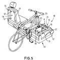
Gemäß Fig. 5 trägt die Haltefläche H des modulartigen
Flächenelements 15 als Fahrzeug-Ausstattungsteil
21 je einen Gabelhalter für eine Fahrrad-Vorradgabel
26. Die Gabelhalter 21 besitzen in nicht dargestellter
Weise nach unten ragende Gegenhalterastelemente
(Zapfen) 20, welche mit den Halterastelementen 19 der
Haltefläche H des modulartigen Flächenelements 15 zusammenwirken.
Grundsätzlich ist es auch möglich und im
Rahmen der Erfindung liegend, die Gabelhalter 21 einstückig
mit dem modulartigen Flächenelement 15 auf der
Haltefläche H anzuordnen.5 carries the holding surface H of the
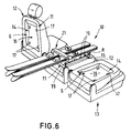
Gemäß Fig. 6 ist das Fahrzeug-Ausstattungsteil 21
von einem klappbaren Ski-Haltebügel gebildet. An jedem
Ende weist der Ski-Haltebügel 21 ein nach unten ragendes
Gegenhalterastelement (Zapfen) 20 auf, welcher mit
je einem matrizenförmigen Halterastelement 19 der Haltefläche
H kooperiert.6, the
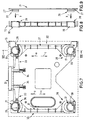
In den Fig. 7-9 ist das Zusammenwirken der Rastelemente in mehr konstruktiver Weise dargestellt.7-9 is the interaction of the locking elements presented in a more constructive way.
Das plattenförmige modulartige Flächenelement 15
weist vier matrizenartige Halterastelemente 19 auf, in
welche zapfenartige Gegenrastelemente 20 eines Fahrzeug-Ausstattungsteils
21 (hier als Bodenelement lediglich
als pars pro toto dargestellt) in Einführrichtung
y eingesetzt werden können. Die im wesentlichen
rotationssymmetrischen Zapfen 20 weisen jeweils eine
sich über den Umfang erstreckende nach außen offene
Ringnut 27 auf, welche jeweils von einem gabelförmig
ausgebildeten Riegel 28 umgriffen ist. Hierzu bildet
jede Gabel 28 eine innenliegende Sperrkante 29 und eine
außenliegende Sperrkante 30. Auf diese Weise können die
Gabeln 28 in derselben Verriegelungsrichtung a gemeinsam
verriegeln und in derselben Entriegelungsrichtung c
gemeinsam entriegeln.The plate-shaped module-
Jeweils zwei Gabeln 28 sind über ein Mittelteil 31
zu einem etwa hantelförmigen Gesamtbauteil 32 miteinander
verbunden. Beide hantelförmigen Bauteile 32 können
mittels der Betätigungshandhabe B über deren Mitnehmerstege
33 bewegungseinheitlich bedient werden. Dabei erfolgt
der Entriegelungshub in Richtung c entgegen der
Rückstellkraft der beiden Schraubendruckfedern 34.In each case two
Die mit den Rastelementen 17 des fahrzeugseitigen
Einbaufeldes zusammenwirkenden Gegenrastelemente 18
sind in den Fig. 7 und 8 nicht dargestellt. Es ist indessen
vorstellbar, daß die Gegenrastelemente 18 ebenfalls
von den als Durchgangsöffnung ausgebildeten Halterastelementen
19 matrizenförmig ausgestaltet und mit
zusätzlichen Verriegelungsgabeln 28 versehen sein können.
In einem solchen Falle wären die einbaufeldseitigen
Rastelemente 17 als nach außen weisende Rastzapfen,
ähnlich den Gegenhalterastelementen (Zapfen) 20, gestaltet.The with the locking
Claims (15)
Applications Claiming Priority (2)
| Application Number | Priority Date | Filing Date | Title |
|---|---|---|---|
| DE19854240 | 1998-11-24 | ||
| DE19854240A DE19854240A1 (en) | 1998-11-24 | 1998-11-24 | Load securing device for passenger cars, such as for combination vehicles, people carriers or the like. |
Publications (3)
| Publication Number | Publication Date |
|---|---|
| EP1004475A2 true EP1004475A2 (en) | 2000-05-31 |
| EP1004475A3 EP1004475A3 (en) | 2003-02-05 |
| EP1004475B1 EP1004475B1 (en) | 2003-11-12 |
Family
ID=7888882
Family Applications (1)
| Application Number | Title | Priority Date | Filing Date |
|---|---|---|---|
| EP99117509A Expired - Lifetime EP1004475B1 (en) | 1998-11-24 | 1999-09-04 | Device for securing loads in passenger vehicles,such as estate cars, large volume passenger cars or similar |
Country Status (4)
| Country | Link |
|---|---|
| US (1) | US6375399B1 (en) |
| EP (1) | EP1004475B1 (en) |
| DE (2) | DE19854240A1 (en) |
| ES (1) | ES2210926T3 (en) |
Cited By (5)
| Publication number | Priority date | Publication date | Assignee | Title |
|---|---|---|---|---|
| FR2895338A1 (en) * | 2005-12-22 | 2007-06-29 | Renault Sas | SEAT BACKREST ARRANGEMENT OF A MOTOR VEHICLE |
| FR2985475A1 (en) * | 2012-01-10 | 2013-07-12 | Peugeot Citroen Automobiles Sa | Vehicle, has deformable tunnel deployed towards bulk-heading position to define loading space on lower loading surface, where lateral walls or lower wall of tunnel are or is directly fixed to surface on parts of their preset length |
| FR2986753A1 (en) * | 2012-02-13 | 2013-08-16 | Peugeot Citroen Automobiles Sa | Protection device for protecting occupant in vehicle e.g. lorry against side shifting of long object, has first panel comprising two parts that are hinged with each other to unfold first and second panels simultaneously |
| FR2989039A1 (en) * | 2012-04-10 | 2013-10-11 | Peugeot Citroen Automobiles Sa | Long load storage device for use on rear face of backrest of car seat, has storage space whose intermediate wall is adapted to move wall beyond front end of folded backrest so as to extend storage space beyond front end of backrest |
| WO2021137968A1 (en) * | 2019-12-31 | 2021-07-08 | Gm Cruise Holdings Llc | Interior delivery box |
Families Citing this family (23)
| Publication number | Priority date | Publication date | Assignee | Title |
|---|---|---|---|---|
| US6742837B1 (en) | 2002-02-27 | 2004-06-01 | David P. Alexander | Car seat netting systems |
| DE10228360A1 (en) * | 2002-06-25 | 2004-01-15 | Volkswagen Ag | Frame for positioning objects in a vehicle interior comprises bars for removable fixing onto the side walls, base and roof of the interior, and bars having quick-fastening locking devices for removably locking onto the first bars |
| DE10236774B4 (en) * | 2002-08-10 | 2005-09-22 | Kaiser, Andreas, Dipl.-Ing. (BA) | Mounting bracket for the vehicle interior |
| DE10333630B4 (en) * | 2002-12-11 | 2004-10-21 | Uebler Gmbh | Fastening device for a transport good and its use in particular for a bicycle |
| DE10260504A1 (en) | 2002-12-21 | 2004-07-01 | Adam Opel Ag | Carrier system for additional interior fittings |
| DE10357356A1 (en) * | 2003-12-09 | 2005-07-07 | Sitech Sitztechnik Gmbh | Object holding device for mounting on the middle armrest of a vehicle seat has fastening brackets with which it is detachably connected to a pivoting middle armrest carrier element |
| GB2424575B (en) * | 2005-04-01 | 2009-02-25 | Johnson Controls Automotive Uk | An anchor support for interchangeable modules |
| DE102005029697A1 (en) * | 2005-06-24 | 2006-12-28 | Wilhelm Karmann Gmbh | Backrest for use in vehicle seat, has luggage box designed such that box is hinged into flat position, in which box rests against rear side of backrest, and is folded into usage position, in which box is usable as transport container |
| US20070057526A1 (en) * | 2005-09-09 | 2007-03-15 | Bigelow Jason A | Vehicle with interchangeable accessories |
| DE102006023948B4 (en) * | 2006-05-17 | 2015-09-03 | Stefanie Schanen | Transport container system |
| DE102006029311B3 (en) * | 2006-06-23 | 2008-03-13 | Bos Gmbh & Co. Kg | Manually lockable module box |
| EP2030842A3 (en) * | 2007-08-29 | 2012-10-17 | Mazda Motor Corporation | Storage box structure for vehicle |
| US20090266773A1 (en) * | 2008-04-29 | 2009-10-29 | Jeremy Janeczko | Portable bike carrier |
| DE102008030236A1 (en) | 2008-06-25 | 2009-12-31 | GM Global Technology Operations, Inc., Detroit | Vehicle seat for use as middle seat of e.g. combi-van, has adapter part with receiver supported in backrest part, and rails supported in receiver for displaceable support of functional part, where backrest part exhibits projection or recess |
| US8387734B2 (en) * | 2009-03-06 | 2013-03-05 | Polaris Industries Inc. | Low speed vehicle |
| DE102009033107B4 (en) * | 2009-07-15 | 2020-10-29 | Volkswagen Ag | Device for the fixed, but detachable fastening of an attachment to a supporting component of a vehicle and a vehicle with such a device |
| US20110278334A1 (en) * | 2010-04-28 | 2011-11-17 | Jorg Aadahl | Individually adaptable universal organizing container for auto sundry |
| DE102012009556A1 (en) | 2012-05-12 | 2013-11-14 | Daimler Ag | Adapter device for mounting e.g. vehicle seat, in inner space of motor car, has mounting system for partially fastening inner space component, and another mounting system for fastening adapter device at inner space bottom of motor car |
| US20140367431A1 (en) * | 2013-06-14 | 2014-12-18 | Keith Sutter | Bicycle carrier apparatus |
| DE102017104763A1 (en) | 2017-03-07 | 2018-09-13 | Dr. Ing. H.C. F. Porsche Aktiengesellschaft | motor vehicle |
| EP3828028A1 (en) | 2019-11-29 | 2021-06-02 | MAGNA STEYR Fahrzeugtechnik AG & Co KG | Cargo area expansion |
| US11697365B2 (en) * | 2021-11-04 | 2023-07-11 | Lear Corporation | Seat assembly |
| DE102022117095B4 (en) * | 2022-07-08 | 2024-08-08 | Next.E.Go Mobile SE | STORAGE ARRANGEMENT OF A SUPPORT FRAME ON A BACK OF A VEHICLE SEAT AND SUPPORT FRAME FOR A MOTOR VEHICLE |
Citations (3)
| Publication number | Priority date | Publication date | Assignee | Title |
|---|---|---|---|---|
| DE9311587U1 (en) | 1993-08-03 | 1994-12-01 | Casimir, Wolf von, 82327 Tutzing | Protection device for vehicle occupants |
| DE19513215C1 (en) | 1995-04-12 | 1996-05-02 | Butz Peter Verwaltung | Load securing device for cars |
| DE29711198U1 (en) | 1997-06-27 | 1997-10-09 | Peter Butz Gmbh & Co Verwaltungs-Kg, 40764 Langenfeld | Transport container device for installation in motor vehicles, in particular for installation on the seat back in passenger cars |
Family Cites Families (10)
| Publication number | Priority date | Publication date | Assignee | Title |
|---|---|---|---|---|
| US1796502A (en) * | 1928-06-22 | 1931-03-17 | Boucher Alexander Raymond | Carrying case equipped with lock-controlled attaching means |
| US3132781A (en) * | 1961-05-31 | 1964-05-12 | Frank G Poczatek | Collapsible carrier device |
| DE7430905U (en) * | 1974-09-13 | 1975-12-11 | Intec | Carrier mat and locking means for securing objects on flat surfaces and on walls, in particular to prevent loads from slipping on vehicles |
| US4020986A (en) * | 1975-05-02 | 1977-05-03 | Mcatee James L | Console caddy |
| US4739637A (en) * | 1984-05-14 | 1988-04-26 | Vaultec Industries, Inc. | Locking device for portable equipment |
| IT1224218B (en) * | 1987-12-22 | 1990-09-26 | Clover Srl | HOLDER WITH SUCKER ATTACHMENT ESPECIALLY SUITABLE FOR MOTORCYCLES |
| DE4222024A1 (en) * | 1992-07-04 | 1994-01-05 | Bayerische Motoren Werke Ag | Transport goods fastener in station wagon luggage space - has clamping bolt for securing e.g. bicycle fork on fixed retainer in luggage space. |
| DE4438909C1 (en) * | 1994-11-03 | 1996-03-21 | Butz Fahrzeugteile Gmbh | Transport device for motor vehicles, such as. B. for combination cars or large passenger cars |
| DE19604714A1 (en) * | 1996-02-09 | 1997-08-14 | Butz Peter Verwaltung | Transport device for motor vehicles, such as. B. for combination cars or large passenger cars |
| US5788310A (en) * | 1997-01-23 | 1998-08-04 | Mckee; Eric R. | Pickup truck bed liner dividing system |
-
1998
- 1998-11-24 DE DE19854240A patent/DE19854240A1/en not_active Withdrawn
-
1999
- 1999-09-04 EP EP99117509A patent/EP1004475B1/en not_active Expired - Lifetime
- 1999-09-04 ES ES99117509T patent/ES2210926T3/en not_active Expired - Lifetime
- 1999-09-04 DE DE59907704T patent/DE59907704D1/en not_active Expired - Lifetime
- 1999-11-23 US US09/447,694 patent/US6375399B1/en not_active Expired - Fee Related
Patent Citations (3)
| Publication number | Priority date | Publication date | Assignee | Title |
|---|---|---|---|---|
| DE9311587U1 (en) | 1993-08-03 | 1994-12-01 | Casimir, Wolf von, 82327 Tutzing | Protection device for vehicle occupants |
| DE19513215C1 (en) | 1995-04-12 | 1996-05-02 | Butz Peter Verwaltung | Load securing device for cars |
| DE29711198U1 (en) | 1997-06-27 | 1997-10-09 | Peter Butz Gmbh & Co Verwaltungs-Kg, 40764 Langenfeld | Transport container device for installation in motor vehicles, in particular for installation on the seat back in passenger cars |
Cited By (9)
| Publication number | Priority date | Publication date | Assignee | Title |
|---|---|---|---|---|
| FR2895338A1 (en) * | 2005-12-22 | 2007-06-29 | Renault Sas | SEAT BACKREST ARRANGEMENT OF A MOTOR VEHICLE |
| FR2985475A1 (en) * | 2012-01-10 | 2013-07-12 | Peugeot Citroen Automobiles Sa | Vehicle, has deformable tunnel deployed towards bulk-heading position to define loading space on lower loading surface, where lateral walls or lower wall of tunnel are or is directly fixed to surface on parts of their preset length |
| FR2986753A1 (en) * | 2012-02-13 | 2013-08-16 | Peugeot Citroen Automobiles Sa | Protection device for protecting occupant in vehicle e.g. lorry against side shifting of long object, has first panel comprising two parts that are hinged with each other to unfold first and second panels simultaneously |
| FR2989039A1 (en) * | 2012-04-10 | 2013-10-11 | Peugeot Citroen Automobiles Sa | Long load storage device for use on rear face of backrest of car seat, has storage space whose intermediate wall is adapted to move wall beyond front end of folded backrest so as to extend storage space beyond front end of backrest |
| WO2021137968A1 (en) * | 2019-12-31 | 2021-07-08 | Gm Cruise Holdings Llc | Interior delivery box |
| US11440478B2 (en) | 2019-12-31 | 2022-09-13 | Gm Cruise Holdings Llc | Interior delivery box |
| CN115190850A (en) * | 2019-12-31 | 2022-10-14 | 通用汽车巡航控股有限责任公司 | Internal delivery box |
| EP4084994A1 (en) * | 2019-12-31 | 2022-11-09 | GM Cruise Holdings LLC | Interior delivery box |
| EP4084994B1 (en) * | 2019-12-31 | 2026-01-07 | GM Cruise Holdings LLC | Interior delivery box |
Also Published As
| Publication number | Publication date |
|---|---|
| DE59907704D1 (en) | 2003-12-18 |
| DE19854240A1 (en) | 2000-05-31 |
| US6375399B1 (en) | 2002-04-23 |
| EP1004475B1 (en) | 2003-11-12 |
| EP1004475A3 (en) | 2003-02-05 |
| ES2210926T3 (en) | 2004-07-01 |
Similar Documents
| Publication | Publication Date | Title |
|---|---|---|
| EP1004475B1 (en) | Device for securing loads in passenger vehicles,such as estate cars, large volume passenger cars or similar | |
| EP0738626B1 (en) | Device for variable partitioning of a luggage compartment of a motor vehicle and for retaining freight | |
| EP1180452A2 (en) | Fixing device for rigid suitcases in a load compartment of a vehicle | |
| DE102004041583A1 (en) | Article e.g. cooling box, attaching device for use in vehicle, has adapter plate with pin section on its lower surface for locking in seat rail, and slider and locking device are placed between release and contact positions at article | |
| EP0940289A2 (en) | Vehicle seat arrangement with a modular insert which forms a holding opening such as a loading opening | |
| DE102005046876A1 (en) | Seat row of a motor vehicle with an arranged between two outer seats armrest | |
| EP0713806B1 (en) | Closure/retaining device for trimming part of a motor vehicle | |
| DE102018211346A1 (en) | motor vehicle | |
| EP0385191B1 (en) | Loading space covering device for motor vehicles, especially for estate cars | |
| DE102008019396B4 (en) | Cargo space for a motor vehicle | |
| DE102008027421A1 (en) | Load-bearing cover assembly with support ribs that facilitate the handling of cargo | |
| DE20110923U1 (en) | Transport container device for vehicles, such as Durchladeeinrichtung | |
| DE29821030U1 (en) | Load securing device for passenger cars, such as for combination cars, people carriers or the like. | |
| DE4128701A1 (en) | PROTECTIVE WALL FOR SEPARATING THE PASSENGER'S ROOM OF A MOTOR VEHICLE FROM A LOADING AREA LOCATED BEHIND | |
| EP0893306A2 (en) | Boot arrangement for installation in motor vehicles, in particular for the seat back of a motor car | |
| EP1749698A2 (en) | Luggage compartment cover | |
| DE102005036805A1 (en) | Loading space partition for expandable loading space of motor vehicle, has two dividing elements whereby detent or locking means are cooperated further to produce two hinge connections on second dividing element | |
| EP3756943B1 (en) | Device for fixing an object | |
| DE19731370C1 (en) | Protective screen for separating loading section and passenger section of motor vehicle | |
| DE102005002581B4 (en) | Motor vehicle loading space | |
| DE20019704U1 (en) | Loading space covering and / or loading space separating device for the loading or luggage space of a vehicle | |
| DE102011009218A1 (en) | Cargo securing device for a vehicle and arrangement of a load securing device in a vehicle | |
| DE10228360A1 (en) | Frame for positioning objects in a vehicle interior comprises bars for removable fixing onto the side walls, base and roof of the interior, and bars having quick-fastening locking devices for removably locking onto the first bars | |
| DE102020124167A1 (en) | Holder assembly for a mounting structure and organization system with the holder assembly | |
| DE102019128985B4 (en) | trunk cover |
Legal Events
| Date | Code | Title | Description |
|---|---|---|---|
| PUAI | Public reference made under article 153(3) epc to a published international application that has entered the european phase |
Free format text: ORIGINAL CODE: 0009012 |
|
| AK | Designated contracting states |
Kind code of ref document: A2 Designated state(s): AT BE CH CY DE DK ES FI FR GB GR IE IT LI LU MC NL PT SE |
|
| AX | Request for extension of the european patent |
Free format text: AL;LT;LV;MK;RO;SI |
|
| PUAL | Search report despatched |
Free format text: ORIGINAL CODE: 0009013 |
|
| AK | Designated contracting states |
Designated state(s): AT BE CH CY DE DK ES FI FR GB GR IE IT LI LU MC NL PT SE |
|
| AX | Request for extension of the european patent |
Extension state: AL LT LV MK RO SI |
|
| 17P | Request for examination filed |
Effective date: 20030102 |
|
| GRAH | Despatch of communication of intention to grant a patent |
Free format text: ORIGINAL CODE: EPIDOS IGRA |
|
| GRAS | Grant fee paid |
Free format text: ORIGINAL CODE: EPIDOSNIGR3 |
|
| GRAA | (expected) grant |
Free format text: ORIGINAL CODE: 0009210 |
|
| AKX | Designation fees paid |
Designated state(s): DE ES FR GB IT |
|
| AK | Designated contracting states |
Kind code of ref document: B1 Designated state(s): DE ES FR GB IT |
|
| REG | Reference to a national code |
Ref country code: GB Ref legal event code: FG4D Free format text: NOT ENGLISH |
|
| RAP2 | Party data changed (patent owner data changed or rights of a patent transferred) |
Owner name: BOS GMBH & CO. KG |
|
| REF | Corresponds to: |
Ref document number: 59907704 Country of ref document: DE Date of ref document: 20031218 Kind code of ref document: P |
|
| REG | Reference to a national code |
Ref country code: IE Ref legal event code: FG4D Free format text: GERMAN |
|
| GBT | Gb: translation of ep patent filed (gb section 77(6)(a)/1977) |
Effective date: 20040112 |
|
| ET | Fr: translation filed | ||
| REG | Reference to a national code |
Ref country code: IE Ref legal event code: FD4D |
|
| REG | Reference to a national code |
Ref country code: ES Ref legal event code: FG2A Ref document number: 2210926 Country of ref document: ES Kind code of ref document: T3 |
|
| PLBE | No opposition filed within time limit |
Free format text: ORIGINAL CODE: 0009261 |
|
| STAA | Information on the status of an ep patent application or granted ep patent |
Free format text: STATUS: NO OPPOSITION FILED WITHIN TIME LIMIT |
|
| 26N | No opposition filed |
Effective date: 20040813 |
|
| PG25 | Lapsed in a contracting state [announced via postgrant information from national office to epo] |
Ref country code: IT Free format text: LAPSE BECAUSE OF NON-PAYMENT OF DUE FEES;WARNING: LAPSES OF ITALIAN PATENTS WITH EFFECTIVE DATE BEFORE 2007 MAY HAVE OCCURRED AT ANY TIME BEFORE 2007. THE CORRECT EFFECTIVE DATE MAY BE DIFFERENT FROM THE ONE RECORDED. Effective date: 20050904 |
|
| PGFP | Annual fee paid to national office [announced via postgrant information from national office to epo] |
Ref country code: ES Payment date: 20080922 Year of fee payment: 10 |
|
| PGFP | Annual fee paid to national office [announced via postgrant information from national office to epo] |
Ref country code: GB Payment date: 20080922 Year of fee payment: 10 |
|
| GBPC | Gb: european patent ceased through non-payment of renewal fee |
Effective date: 20090904 |
|
| PG25 | Lapsed in a contracting state [announced via postgrant information from national office to epo] |
Ref country code: GB Free format text: LAPSE BECAUSE OF NON-PAYMENT OF DUE FEES Effective date: 20090904 |
|
| REG | Reference to a national code |
Ref country code: ES Ref legal event code: FD2A Effective date: 20110714 |
|
| PG25 | Lapsed in a contracting state [announced via postgrant information from national office to epo] |
Ref country code: ES Free format text: LAPSE BECAUSE OF NON-PAYMENT OF DUE FEES Effective date: 20110704 |
|
| PG25 | Lapsed in a contracting state [announced via postgrant information from national office to epo] |
Ref country code: ES Free format text: LAPSE BECAUSE OF NON-PAYMENT OF DUE FEES Effective date: 20090905 |
|
| PGFP | Annual fee paid to national office [announced via postgrant information from national office to epo] |
Ref country code: FR Payment date: 20111005 Year of fee payment: 13 |
|
| PGFP | Annual fee paid to national office [announced via postgrant information from national office to epo] |
Ref country code: DE Payment date: 20120926 Year of fee payment: 14 |
|
| REG | Reference to a national code |
Ref country code: FR Ref legal event code: ST Effective date: 20130531 |
|
| PG25 | Lapsed in a contracting state [announced via postgrant information from national office to epo] |
Ref country code: FR Free format text: LAPSE BECAUSE OF NON-PAYMENT OF DUE FEES Effective date: 20121001 |
|
| REG | Reference to a national code |
Ref country code: DE Ref legal event code: R119 Ref document number: 59907704 Country of ref document: DE Effective date: 20140401 |
|
| PG25 | Lapsed in a contracting state [announced via postgrant information from national office to epo] |
Ref country code: DE Free format text: LAPSE BECAUSE OF NON-PAYMENT OF DUE FEES Effective date: 20140401 |