Disclosure of Invention
The invention provides a modulation method for multiplicative multiple access channels in a symbiotic wireless communication system, and simultaneously provides a parameter optimization method for the proposed modulation scheme.
The invention provides a novel air modulation scheme. The scheme comprises two components, wherein one part is a symbol time-invariant component and is used for assisting information transmission of a main system; the other part is a symbol time-varying component for transmitting information of the subsystem. The scheme combines two functions of secondary transmitter assistance and information transmission. Meanwhile, because the secondary transmitter adopts passive backscattering technology, the sum of the two components is less than one.
In the scheme of the invention, the error rate performance of the primary and secondary communication systems can be compromised by adjusting the energy of the two components. Specifically, the larger the energy of the constant component in the symbol time is, the better the auxiliary effect on the main system is, and the better the bit error rate performance of the main system is. However, as the energy of the time-invariant component of the symbol increases, the energy of the time-variant component of the symbol decreases, thereby reducing the bit error rate performance of the subsystem. Therefore, the design of the two components is important to the improvement of the error rate of the primary and secondary communication systems, and the two components need to be combined and optimally designed.
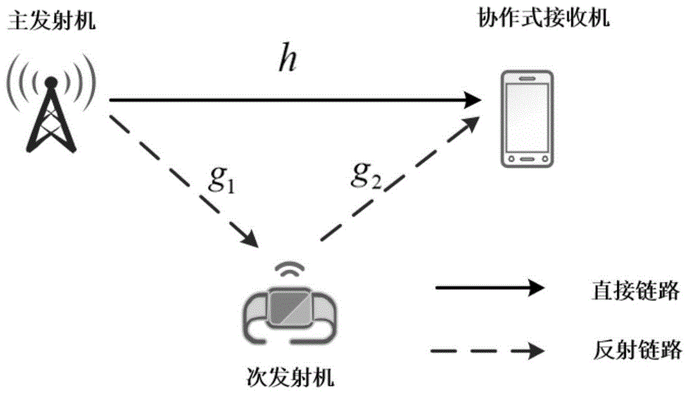
The present invention contemplates a symbiotic wireless communication system model as shown in fig. 1 that includes a primary transmitter, a secondary transmitter, and a cooperative receiver, each device configured with a single antenna. The system model corresponds to an intelligent home model in an actual application scene, wherein the Internet of things sensor modulates acquired environmental information on a radio frequency signal from WiFi by using a backscattering technology, and reflects the modulated signal to the intelligent mobile phone. Thus, the smart phone can jointly demodulate the information from the WiFi access point and the environment information of the Internet of things sensor.
Next, a link transmission model of the communication system is described. Let h e C denote the channel from the primary transmitter to the cooperative receiver g 1 E C denotes the channel from the primary to the secondary transmitter g 2 E C represents the channel from the secondary transmitter to the cooperative receiver.
In addition, let
And->
Normalized constellation point set representing primary and secondary transmitters, < >>
And
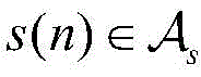
the symbol representing the nth primary transmitter and the symbol of the nth secondary transmitter, p representing the power of the primary transmitter. In this way, the received signal at the cooperative receiver can be expressed as
Wherein g=ρg
1 g
2 ρ represents the reflection efficiency of the secondary transmitter apparatus; z (n) represents additive noise at the end of the cooperative receiver and obeys complex gaussian distribution
Γ (c (n)) represents the reflection coefficient of the secondary transmitter as a function of the secondary transmitter symbol.
According to equation (1), the modulation scheme proposed by the present invention is expressed as follows
Wherein α represents a symbol time-invariant component for assisting transmission of primary system information; βc (n) represents a time-varying component of the symbol used to transmit the secondary system information, β being referred to herein as a multiplicative factor.
By using the modulation scheme in equation (2), the received signal at the cooperative receiver can be expressed as
As can be seen from equation (3), the symbols of the secondary transmitter and the primary transmitter appear in the received signal in a multiplicative manner, and thus the symbiotic wireless communication system can also be modeled as a multiplicative multiple access channel.
Let x (n) denote the combined signal consisting of the primary and secondary transmitter signals, expressed as
The received signal can be rewritten as
The following gives a proposed receiver design. The combined signal is first demodulated and then the demodulated primary and secondary signals are obtained according to the mapping rule of the combined signal to the primary and secondary signals. The demodulation steps are as follows
wherein the method comprises the steps of
The set of constellation points representing the combined signal x (n) can be derived using equation (4).
From the two demodulation steps described above, it can be seen that the bit error rate of the primary and secondary transmitter signals is correlated with the bit error rate of the combined signal. If it is desired to ensure the bit error rate of the primary and secondary transmitter signals, it is first necessary to ensure that the combined signal is correctly demodulated, and then a bit mapping rule is designed to minimize the number of erroneous bits when mapping from the combined signal to the primary and secondary transmitter signals. Note that the parameters α and β in the modulation scheme affect the demodulation performance of the combined signal and the bit mapping rules. Therefore, the two important parameters need to be optimized to improve the error rate performance of the combined signal, and further improve the performance of the primary and secondary transmitter signals.
The beneficial effects of the invention are as follows: the invention provides a modulation scheme design for multiplicative multiple access channels in symbiotic wireless communication. The modulation scheme has the functions of transmitting self information and assisting communication, is simple to implement, and has high application value.
Detailed Description
The technical scheme of the present invention is described in detail below with reference to the embodiments and the accompanying drawings.
Take a typical symbiotic wireless communication system as an example. As shown in FIG. 1, the present invention contemplates a primary transmitter, a secondary transmitterThe transmitter and the cooperative receiver are all provided with a single antenna. Order the
And->
Representing a normalized set of constellation points for the primary and secondary transmitters,
and->
The symbol representing the nth primary transmitter and the symbol of the nth secondary transmitter, p representing the power of the primary transmitter. In this way, the received signal at the cooperative receiver can be expressed as
Where h represents the direct link channel of the primary transmitter to the cooperative receiver; g=ρg
1 g
2 ρ represents the reflection efficiency of the secondary transmitter apparatus, g
1 G represents the channel from the primary transmitter to the secondary transmitter
2 Representing the channel from the secondary transmitter to the cooperative receiver; z (n) represents additive noise at the end of the cooperative receiver and obeys complex gaussian distribution
Alpha represents the symbol time-invariant component of the proposed modulation scheme and beta c (n) represents the symbol time-variant component of the proposed modulation scheme.
Let x (n) denote the combined signal consisting of the primary and secondary transmitter signals, expressed as
The received signal at the cooperating receiver may be rewritten as
The steps of demodulating the primary and secondary transmitter signals by the cooperative receiver are: the combined signal is demodulated using a maximum likelihood detector and then the demodulated primary and secondary transmitter signals are obtained based on a bit mapping rule of the combined signal to the primary and secondary transmitter signals. Can be expressed in the following two steps
wherein the method comprises the steps of
The set of constellation points representing the combined signal x (n) can be derived using equation (9).
From the above two steps, it can be seen that the bit error rate of the primary and secondary transmitter signals is correlated with the bit error rate of the combined signal. If it is desired to ensure the bit error rate of the primary and secondary transmitter signals, it is first necessary to enable the combined signal to be accurately demodulated, and then a bit mapping rule needs to be designed to reduce the number of bits that are wrong in mapping. Because two parameters alpha and beta in the proposal of the invention can influence the minimum Euclidean distance and bit mapping rule of the combined signal, the two parameters need to be designed and optimized to improve the error rate performance of the primary and secondary transmitter signals.
To be used for
For example, the present invention proposes a design methodology that optimizes the parameters α and β. For simplicity of symbology, the time symbol n is omitted from here.
According to the document "J.G.Proakis and M.Salehi, digital communications, mcGraw-hill New York,2001, vol.4", the minimum Euclidean distance of the combined signal and the Hamming distance between adjacent constellation points of the combined signal affect the demodulation performance and the bit mapping rules, respectively, of the combined signal. The analysis is as follows
1) Minimum Euclidean distance: since the larger the minimum distance, the better the demodulation performance of the combined signal, the object of the present invention is to maximize the minimum euclidean distance of the combined signal, expressed as
Wherein D is
m,l Defined as D
m,l =|x
m -x
l |,
2) Hamming distance between adjacent constellation points: according to the document "J.G.Proakis and M.Salehi, digital communications, mcGraw-hill New York,2001, vol.4", the most likely case for demodulation is to judge a point in the neighborhood as a point that is actually transmitted. Therefore, once a symbol is misjudged, it is desirable that the fewer the number of erroneous bits is, the better. The present invention assumes that the primary and secondary transmitter signals are in classical gray coded form, i.e. the constellation point symbols of the primary and secondary transmitters are mapped into bit sequences {00,01,11,10} and {1,0} respectively. The combined signal is then represented as a symbol of 3 bits, where the first two bits represent the primary transmitter signal and the last bit represents the secondary transmitter signal. As shown in fig. 2, fig. 2 (a) shows a bit map of the primary transmitter signal. Given the bit mapping of the primary and secondary transmitter signals, the bit mapping of the combined signal is determined by the parameters α and β. From equation (9), the combined signal can be seen as a rotation of the main transmitter signal, where the phase rotation depends on

And->
In general, under these two conditions
Two rules for bit mapping are shown in fig. 2 (b) and fig. 2 (c). The properties of these two bit mapping schemes are now summarized as follows:
bit mapping scheme I in fig. 2 (b):
only 1 bit differs between two adjacent symbols in the same quadrant,
there are 2 bits different between adjacent symbols in different quadrants.
Bit mapping scheme II in fig. 2 (c):
there are 3 bits different between two adjacent symbols in the same quadrant,
there are 2 bits different between adjacent symbols in different quadrants.
The present invention thus adopts the bit mapping scheme in fig. 2 (b) because the average hamming distance of this scheme is smaller. In order to satisfy the bit map mode I, the parameters need to satisfy the following conditions:
taking into account the two minimum Euclidean distances and the Hamming distance between adjacent constellation points, modeling the following optimization problem
Wherein C3 and C4 represent the constraint that the reflection coefficient modulus of the secondary transmitter is less than 1, i.e., |alpha+βc (n) |1,
since the introduction of the symbol time invariant component α is for assisting the information transmission of the main system, for simplicity, the present invention considers the phase of gα and the h alignment, i.e., +.α= = (h/g), where +.α represents the phase of α.
The invention provides the following optimization method according to the above optimization problem. First, the component is unchanged at a given symbol
In the case of (1) deriving the sign time-varying component +.>
And minimum Euclidean distance->
Is a closed form solution. Then, re-optimize the parameters +.>
To maximize the minimum euclidean distance.
Invariant component given a symbol
In the case of (1), the original problem P1 becomes a single-variable problem, and the variable is β. By drawing the feasible region corresponding to the constraint C1-C4 and combining the objective function, the variable +.>
And minimum Euclidean distance
Is expressed as a closed form solution of
Wherein the method comprises the steps of
Where root (·) represents the root of the equation.
Next, only the minimum Euclidean distance is analyzed
Along with->
The optimal alpha can be found by the monotonicity of the change
* 。
By analysis, it can be found that
In section->
Is monotonically increasing in the interval +.>
The inner is monotonically decreasing in the interval +.>
The inner part is firstly monotonically decreasing and then monotonically increasing. Thus, the minimum Euclidean distance is at the point +.>
Or->
The maximum value is taken. The specific situation varies with the variation of the channel strength ratio h/g.
Thus, the optimal solution of problem P1 is represented by the following five cases
1): i h/g i=0, i.e. the direct link is blocked. The optimal combined signal forms a standard 8PSK constellation, and the optimal solution is expressed as
α * =cos(π/8),β * =-jsin(π/8). (22)
2)0<|h/g|<1, the optimal combined signal forms a scaled 8PSK constellation with scaling factor (1+tan) 2 (π/8))(|h/g|+|α * |) 2 . The optimal solution is expressed as
Wherein the method comprises the steps of
Given by equation (20).
3)
The optimal combined signal constitutes a constellation like 8 QAM. The optimal solution is expressed as
Wherein the method comprises the steps of
Given by equation (19).
4)
The optimal solution is denoted as alpha
* =0,|β
* |=1,
Wherein the method comprises the steps of
5)
The optimal solution is denoted as alpha
* =0,|β
* |=1,∠β
* ∈(-π,0)
Simulation results are given below to verify the superiority of the above modulation scheme over the conventional modulation scheme. The conventional modulation scheme is defined as
Considering that all channels obey the rayleigh fading channel model, the signal-to-noise ratio of the reflective link is defined as
Wherein the method comprises the steps of
And->
Representing channel g
1 And g
2 Is a variance of (c). The reflection efficiency parameter ρ=1, and the direct link channel satisfies |h/g|=const, where const represents a specific channel strength ratio, and the number of channel realizations is 10
6 And twice.
Fig. 3 compares the error rate of the combined signal with the signal-to-noise ratio of the reflected link for different channel strength ratios. The results show that conventional modulation schemes have ambiguity problems due to primary and secondary transmitter signal products when the cooperative receiver demodulates the signal in the case where the direct link is blocked, i.e., the case. Resulting in a bit error rate of 0.5. After the modulation scheme is applied, the superiority of the scheme can be obviously seen, and the error rate performance of the combined signal is greatly improved.
Fig. 4 and 5 compare plots of bit error rate of the primary and secondary transmitter signals with reflected link signal-to-noise ratio for different channel strength ratios, respectively. The result shows that compared with the traditional modulation scheme, especially in the case of weaker direct link, the proposed modulation scheme can greatly improve the error rate of the primary and secondary transmitter signals, and the superiority of the proposed modulation scheme is demonstrated.