CN1202425A - printing device - Google Patents
printing device Download PDFInfo
- Publication number
- CN1202425A CN1202425A CN98102486.6A CN98102486A CN1202425A CN 1202425 A CN1202425 A CN 1202425A CN 98102486 A CN98102486 A CN 98102486A CN 1202425 A CN1202425 A CN 1202425A
- Authority
- CN
- China
- Prior art keywords
- printing
- paper
- printing paper
- image
- cutter
- Prior art date
- Legal status (The legal status is an assumption and is not a legal conclusion. Google has not performed a legal analysis and makes no representation as to the accuracy of the status listed.)
- Granted
Links
Images


Classifications
-
- B—PERFORMING OPERATIONS; TRANSPORTING
- B41—PRINTING; LINING MACHINES; TYPEWRITERS; STAMPS
- B41J—TYPEWRITERS; SELECTIVE PRINTING MECHANISMS, i.e. MECHANISMS PRINTING OTHERWISE THAN FROM A FORME; CORRECTION OF TYPOGRAPHICAL ERRORS
- B41J11/00—Devices or arrangements of selective printing mechanisms, e.g. ink-jet printers or thermal printers, for supporting or handling copy material in sheet or web form
- B41J11/36—Blanking or long feeds; Feeding to a particular line, e.g. by rotation of platen or feed roller
- B41J11/42—Controlling printing material conveyance for accurate alignment of the printing material with the printhead; Print registering
- B41J11/46—Controlling printing material conveyance for accurate alignment of the printing material with the printhead; Print registering by marks or formations on the paper being fed
-
- B—PERFORMING OPERATIONS; TRANSPORTING
- B41—PRINTING; LINING MACHINES; TYPEWRITERS; STAMPS
- B41J—TYPEWRITERS; SELECTIVE PRINTING MECHANISMS, i.e. MECHANISMS PRINTING OTHERWISE THAN FROM A FORME; CORRECTION OF TYPOGRAPHICAL ERRORS
- B41J11/00—Devices or arrangements of selective printing mechanisms, e.g. ink-jet printers or thermal printers, for supporting or handling copy material in sheet or web form
- B41J11/66—Applications of cutting devices
- B41J11/663—Controlling cutting, cutting resulting in special shapes of the cutting line, e.g. controlling cutting positions, e.g. for cutting in the immediate vicinity of a printed image
-
- B—PERFORMING OPERATIONS; TRANSPORTING
- B41—PRINTING; LINING MACHINES; TYPEWRITERS; STAMPS
- B41J—TYPEWRITERS; SELECTIVE PRINTING MECHANISMS, i.e. MECHANISMS PRINTING OTHERWISE THAN FROM A FORME; CORRECTION OF TYPOGRAPHICAL ERRORS
- B41J11/00—Devices or arrangements of selective printing mechanisms, e.g. ink-jet printers or thermal printers, for supporting or handling copy material in sheet or web form
- B41J11/66—Applications of cutting devices
- B41J11/666—Cutting partly, e.g. cutting only the uppermost layer of a multiple-layer printing material
Landscapes
- Handling Of Sheets (AREA)
- Printers Characterized By Their Purpose (AREA)
Abstract
Description
本发明涉及一种例如具有热打印头等的印像机构的印像装置。The present invention relates to an image printing apparatus having an image printing mechanism such as a thermal print head or the like.
图20为表示传统的印像装置(热转印印像装置)的机构100的原理图。在图20中,1为热转印头、2为涂布有热溶解性油墨或热升华性油墨的热转印记录用油墨座、3为印像纸、4为使油墨座2和印像纸3紧密接触并推向热转印头的压纸滚筒、5为夹执并运送印像纸3的夹送辊、6为用以切断滚筒式印像纸的切刀、7为检测印像纸3前端位置的反射式光学传感器。FIG. 20 is a schematic diagram showing a
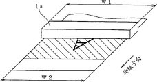
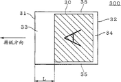
图21为表示传统的热转印头1的原理图。热转印头1的有效发热体宽度W1比印像纸3的纸宽W2窄。图22表示以往所生成图像印页300的表面图。FIG. 21 is a schematic diagram showing a conventional
传统的印像装置的操作如下所述。现假定,切刀6已将印像纸3切断。夹送辊5将印像纸向进纸方向运送。在印像纸传送方向中,由印像纸供给侧指向图像印页排出侧方向称为排纸方向,与此相反的方向称为送纸方向。传感器7检测出印像纸3的前端31。夹送辊5根据由传感器7检测出的印像纸前端31的位置的信息将前端31置于夹送辊5的位置。然后进行所希望图像的印像。其后,夹送辊5向排纸方向传送印像纸3,将未端32置于传感器7的位置,并留有空白34。此后切刀6将印像纸3切断。这样,在传统上根据印像纸3的前端31的位置信息来对准印像纸3的位置。The operation of a conventional printing apparatus is as follows. Assume now that the
在传统的热转印像装置中,存在以下的问题。如图21所示,由于热转印头1的有效发热体宽度W1比印像纸3的宽度W2窄,因此如图22所示,会造成图像印页300上沿宽度方向上的空白35。此外,传统的热转印装置,由于上述的操作,会于图像印页300上造成沿传送方向上的空白,即,产生具有宽度L等于从夹送辊5到热转印头1之间的距离的夹取空白33和为了不致切断图像本身而留的余量空白34。In conventional thermal transfer image devices, there are the following problems. As shown in FIG. 21 , since the effective heating body width W1 of the
此外,印像纸3的位置对准以前端31的位置信息进行,而不是以印像纸3背面的内容来进行。因而,存在不适用于图像印页为例如图画明信片这样,需要表面的内容对准背面内容位置的印像。In addition, the alignment of the
本发明的目的是解决这些问题,提供一种能够产生没有空白的图像印页,并将表面印像位置对准印像纸背面内容的印像装置。The object of the present invention is to solve these problems and provide a printing device capable of producing image prints without blanks and aligning the printing position of the surface with the content on the back of the printing paper.
本发明权利要求1的技术解决方案为,一种连续状印像纸的印像装置,其特征在于,前述印像纸的表面是由于进行所希望的印像的印像面,背面是已进行过所定的印刷的定型印刷区域与空白区域间歇设置的已印刷面,同时在前述空白区域内设置有位置基准,并设有传送印像纸的驱动传送机构;在前述印像纸运送路线上与前述印像纸的表面相对设置,进行前述所希望的印像的印像机构;设置于前述印像机构的前述印像纸的排纸侧的切刀;设置于前述路线上,以检测出前述位置基准的传感器以及根据前述传感器的检测输出控制前述运送机构、前述印像机构及前述切刀的控制装置;前述印像机构根据前述控制装置的控制,对与前述定型印刷区域相对应的前述印像纸的表面进行印像,前述切刀根据前述控制装置的控制,通过由前述印像纸上切掉前述空白区域,生成表面上进行了所希望的印像,而背面具有定型印刷的图像印页。The technical solution of
本发明权利要求2的技术解决方案为,一种连续状印像纸的印像装置,其特征在于,前述印像纸的表面为用于进行所希望的印像的印像面,背面为连续设置有已进行了所定的印刷的定型印刷区域的已印刷面,同时在前述定型印刷内设置有位置基准,并设有传送前述印像纸的驱动传送机构;在前述印像纸运送路线上与前述印像纸的表面相对设置,进行前述所希望的印像的印像机构;设置于前述印像机构中前述印像纸的排纸侧的切刀;设置于前述路线上,以检测出前述位置基准的传感器以及根据前述传感器的检测输出控制前述传送机构、前述印像机构及前述切刀的控制装置,通过该控制装置的控制,前述印像机构对与前述定型印刷区域相对应的前述印像纸的表面进行印像,前述切刀根据前述控制装置的控制,将前述印像纸的前定型印刷区域边界切除,通过上述步骤制成在表面印有所需印像,而在背面进行了定型印刷的纸片。The technical solution of
本发明权利要求3的技术解决方案中,前述印像机构为一种具有大于前述印像纸的纸宽以上的有效发热体宽度的热转印头。In the technical solution of
本发明权利要求4的技术解决方案中,前述定型印刷区域中前述所定的印刷为明信片版面的印刷。In the technical solution of
本发明权利要求5的技术解决方案为,一种单页或连续状的印像纸的热转印印像装置,其特征在于,在运送前述印像纸的路线上设有相对于前述印像纸的印像面设置的热转印头,前述热转印头具有超过前述印像纸的纸宽的有效发热体宽度。The technical solution of
本发明权利要求6的技术解决方案中,具有将前述印像纸以位置基准限定于所定位置上并传送前述印像纸的驱动传送机构、设置于前述印像机构的前述印像纸的排纸侧的切刀;设置于前述路线上,以检测出前述位置基准的传感器以及根据前述传感器的检测输出控制前述运送机构、前述热转印头及前述切刀的控制装置,前述切刀根据前述控制装置的控制,切掉前述印像纸的运送方向上图像区域以外的空白区域。In the technical solution of
本发明权利要求7的技术解决方案为,具有设置于前述路线中前述切刀附近进纸侧的的图像检测装置,前述控制装置根据前述图像检测装置输出替代前述传感器的检测输出来控制切刀。The technical solution of
图1为表示本发明实施例1的印像装置的机构原理图。FIG. 1 is a schematic diagram showing the mechanism of a printing apparatus according to
图2为表示本发明实施例1的印像装置的控制系统框图。Fig. 2 is a block diagram showing a control system of the printing apparatus according to
图3为表示本发明实施例1的热转印头原理图。Fig. 3 is a schematic diagram showing the thermal transfer head of
图4为表示本发明实施例1的印像纸表面图。Fig. 4 is a view showing the surface of the printing paper of Example 1 of the present invention.
图5为表示本发明实施例1的印像纸背面图。Fig. 5 is a back view of the printing paper showing Example 1 of the present invention.
图6为表示本发明实施例1所生成的图像印页表面图。Fig. 6 is a view showing the surface of an image printed sheet produced in
图7为表示本发明实施例1所生成的图像印页背画图。Fig. 7 is a drawing showing the backside of the printed image generated in
图8为表示本发明实施例1的印像装置操作的流程图。Fig. 8 is a flow chart showing the operation of the printing apparatus according to
图9为表示本发明实施例1的印像装置操作的流程图。Fig. 9 is a flow chart showing the operation of the printing apparatus according to
图10为印像纸内各尺寸图。Figure 10 is a diagram of various dimensions in the printing paper.
图11为表示本发明实施例2的印像纸表面图。Fig. 11 is a view showing the surface of a printing paper according to Example 2 of the present invention.
图12为表示本发明实施例2的印像纸背面图。Fig. 12 is a back view of printing paper showing Example 2 of the present invention.
图13为表示本发明实施例2所生成的图像印页表面图。Fig. 13 is a view showing the surface of an image printed sheet produced in
图14为表示本发明实施例2所生成的图像印页背面图。Fig. 14 is a back view of an image printed sheet generated in
图15为表示本发明实施例2的印像装置操作的流程图。Fig. 15 is a flow chart showing the operation of the printing apparatus according to
图16为表示本发明实施例3的印像装置的机构的原理图。Fig. 16 is a schematic diagram showing the mechanism of a printing apparatus according to
图17为表示本发明实施例3的印像纸表面图。Fig. 17 is a view showing the surface of a printing paper according to Example 3 of the present invention.
图18为表示本发明实施例3所生成的图像印页表面图。Fig. 18 is a view showing the surface of an image printed sheet produced in
图19为表示本发明实施例4的印像装置机构的原理图。Fig. 19 is a schematic diagram showing the mechanism of a printing apparatus according to
图20为表示以往印像装置机构的原理图。Fig. 20 is a schematic diagram showing the mechanism of a conventional printing apparatus.
图21为表示以往的热转印头的原理图。Fig. 21 is a schematic diagram showing a conventional thermal transfer head.
图21为表示以往所生成的图像印页表面图。Fig. 21 is a view showing the surface of an image sheet produced conventionally.
符号说明:W1、有效发热体宽度,W2、纸宽,1a、热转印头,3a、3b、3c印像纸,5、夹送辊,6、切刀,7、传感器,7a、图像扫描器,8、脉冲电机,36、标记,37、定型印刷区域,38、空白区,300a、300b、图像印页,310、纸页。Explanation of symbols: W1, effective heating body width, W2, paper width, 1a, thermal transfer head, 3a, 3b, 3c printing paper, 5, pinch roller, 6, cutter, 7, sensor, 7a, image scanning Device, 8, pulse motor, 36, mark, 37, finalized printing area, 38, blank area, 300a, 300b, image printing page, 310, paper page.
实施例1Example 1
首先,对本发明实施例1的印像装置(热转印印像装置)的结构进行说明。图1为表示本发明实施例1的印像装置机构100a的原理图。在图1中,1a为印制所希望图像的热转印头、2为涂布有热溶解性油墨或热升华性油墨的热转印记录用油墨座、3为连续状的滚筒式印像纸、4为将油墨座2和印像纸3a紧密接触并推向热打印头的压纸滚筒、5为夹执并运送印像纸3的夹滚、6为切断印像纸3a的切刀、7为反射式光学传感器、8为回转夹滚5用脉冲电机。First, the configuration of the printing apparatus (thermal transfer printing apparatus) according to
热转印头1a、压纸滚筒4、夹送辊5、传感器7及切刀6设置于传送印像纸3a的通路上。热转印头1a面对于印像纸3a表面设置。压纸滚筒4相对应于印像纸3a的背面设置。热打印头1a及压纸滚筒4相对。夹送辊5及切刀6从热转印头向的排纸方向顺序设置。传感器7设置在例如夹送辊5及切刀6之间的通路上印像纸3a的背面侧。压纸滚筒4、夹送辊5及脉冲电机8构成驱动传送印像纸3a的驱动传送机构。The thermal transfer head 1a, the
将从热转印头1a至传感器7的距离设为L4,将热转印头1a至切刀6的距离设为L5,将传感器7至切刀6的距离设为L6。Let the distance from the thermal transfer head 1a to the
图2为表示本发明实施例1的印像装置的控制系统框图。在图2中,21为模拟图像信号接收端子、22为数字图像信号接收端子、23为将由端子21的模拟图像信号转换为数字图像信号的A/D变换器、24为执行图像信号及控制信号输入输出接口功能的存储控制器、25为将由端子22及A/D转换器23来的数字图像信号通过存储控制器作为图像数据存储用的帧存储器、26为通过存储控制器24接受帧存储器25内的图像数据,将该图像数据变换为印像用数据并向热转印头输出的转印回路、27为控制机构100a内的脉冲电机8、热转印头1a及控制切刀6的机械控制器、28为控制传感器7、存储控制器24及机械控制器27的CPU。由A/D变换器23、存储控制器24、帧存储器25、转印回路26、机械控制器27及CPU28组成的部分(以下称为“CPU28”等)构成控制机构。Fig. 2 is a block diagram showing a control system of the printing apparatus according to
图3为表示本发明实施例1的热转印头原理图。热转印头1a的有效发热体宽度W1最好大于印像纸3a纸宽W2。同时,所谓有效发热体是指热转印头1a在进行印像时发热的部分,它是能够在印像纸上进行印像的部分。Fig. 3 is a schematic diagram showing the thermal transfer head of
以下对有关实施例1的连续状印像纸进行说明。图4为印像纸3a的表面示图,图5为其背面示图。印像纸3a的表面为进行印制所希望的图像印像面例如单色。印像纸3a背面为具有中间隔有空白区域38而间隔设置的已进行过明信片印刷的定型印刷区域37的已印像面。同时,在空白区域设置有构成位置基准的涂黑标记36。此外,C1为定型印刷区域37及空白区域38的排纸侧的边界(剪切位置),C2为为定型印刷区域37空白区域38的给纸侧的边界,L1为从标记36到剪切位置C2的距离。The continuous printing paper of Example 1 will be described below. Fig. 4 is a front view of the printing paper 3a, and Fig. 5 is a back view thereof. The surface of the printing paper 3a is a desired image printing surface for printing, for example, monochrome. The back side of the printing paper 3a is the printed surface having postcard-printed
图6为本发明实施例1所生成的图像印页表面示图,图7为其背面示图。图像印页300a的背面为定型印刷区域37。纸页310的背面为空白区域38。图像印页300a表面进行所希望的印像,背面进行明信片面的印像。311及312是作为由切刀进行切断时预留余量的残留印刷图像。Fig. 6 is a front view of the image printed sheet generated in
以下利用图1、图2、图8-图10对实施例1的印像装置的操作进行说明。在实施例1的印像装置操作中,图8为表示根据CPU28等的控制进行的初期设定动作的流程图。图9为表示根据CPU28等的控制进行的图像印页生成操作的流程图。图10为印像纸3a内各尺寸图。在图10中,L3为图6的切断余量在传送方向的长度,L4为由剪切位置C1及C2间的长度拉出L3的长度,L2是印像长度,其它符号与图5及图6相对应。The operation of the printing apparatus of
首先,参照图8对印像装置的初期设定操作进行说明。将印像纸3a安装于印像装置上(步骤S101),开始初期设定(步骤S102)。First, the initial setting operation of the printing apparatus will be described with reference to FIG. 8 . Install the printing paper 3a on the printing device (step S101), and start the initial setting (step S102).
然后在以下步骤S103一步骤S110中,由切刀6切断剪切位置C2。详述如下,通过夹送辊5转送印像纸3a,令位于印像纸3a前端的标记36接近传感器7(步骤S103)。传感器7检测出印像纸3a的标记36(步骤104)时,夹送辊5暂时停止传送(步骤S105)。此时,标记36位于传感器7的位置。接着,传感器7通过光线的照射,接收其反射光线,能够检测出标记36及印像纸3a的前端。CPU28读出预先设定的移动量(这里为L1及L6的差),对机械控制器27进行设定(步骤S106)。其中L1比L6长。然后,夹送辊5向进纸方向传送印像纸3a(步骤S107)。夹送辊5将印像纸3a传送到恰好为向机械控制器27设定的移动量时(步骤S108),传送停止(步骤S109)。此时,剪切位置C2位于切刀6处。切刀6将印像纸3a切断。(步骤S110)。Then, in the following step S103 to step S110, the cutting position C2 is cut by the
进行了印像装置的初期设定之后,进行图像印页的生成。首先参照图9,在步骤S201—步骤S205中,进行在印像纸3a的表面印制所希望的图像。详述如下,夹送辊5向进纸方向传送印像纸3a(步骤S201)。传感器7检测出位于印像纸3a的前端的剪切位置C2时(步骤S202),CPU28输出印像指令。此时,CPU28向存储控制器24及机械控制器27输出印像指令(步骤S203)。作为回应,夹送辊5在开始向排纸方向运送印像纸,同时,与此相连动,热转印头1a根据帧存储器26经存储控制器24及转印回路26发出的图像数据开始进行热转印(步骤S204)。夹送辊5将印像纸3a向排纸方向移动长度L2。进行长度为L2的所希望的印像(步骤S205)。这样,在印像纸3a的表面进行所希望的印像。After the initial setting of the printing device is performed, an image sheet is created. Referring first to FIG. 9, in step S201-step S205, a desired image is printed on the surface of the printing paper 3a. As described in detail below, the
在步骤S201及步骤S202中,由于印像纸3a的前端回到传感器7的位置,能够缩短图6的纸页310的在传送方向上的长度。从而,在步骤S202中对印像纸3a的前端的检测并不是为了将表面内容与背面内容对准。In steps S201 and S202, since the front end of the printing paper 3a returns to the position of the
在步骤S206到步骤S210中,由切刀6切断剪切位置C1。详述如下,CPU28读出预先设定的移动量,对机械控制器进行设定(步骤S206)。然后,夹送辊5向进纸方向传送印像纸3a(步骤S207)。一旦夹送辊5在进纸方向将印像纸3a传送CPU28所设定的移动量(步骤S208),传送停止(步骤S209)。此时,剪切位置C1处于切刀6的位置。切刀6将印像纸3a切断(步骤210)。In steps S206 to S210 , the cutting position C1 is cut by the
步骤S206中设定的移动量如下所述,在步骤S205的处理结束时,所希望的图像的前端位于由切刀6向排纸方向伸出的位置,所希望的图像未端位于热转印头1a位置。因而,为使剪切位置C1位于切刀5的位置,首先,将印像纸3向进纸方向移动一个由切刀6伸出的部分(L2-L5),再向排纸方向移动L3。即,步骤S206的移动量L7为L2-L5+L3。The amount of movement set in step S206 is as follows. When the processing in step S205 ends, the front end of the desired image is located at the position where the
接着与图8的步骤S103-步骤S110同样,剪切位置C2由切刀6切断。Next, the cutting position C2 is cut by the
如上所述,由传感器7识别印像纸3a的标记36,通过CPU28等根据传感器的检测输出对热转印头1a、切刀6的控制,热转印头1a对对应于定型印刷区域37的印像纸3a的表面进行热转印,通过切刀6从印像纸3a上切掉空白区域38,印像装置生成如图6及图7所示的图像印页。As mentioned above, the
实施例1的效果如下。The effects of Example 1 are as follows.
如图6所示,由于没有图22中的空白33、空白34及空白35,能够生成与无边框照片非常相似的图像印页300。As shown in FIG. 6, since there are no
能够正确地对准印像纸3a背面的定型区域37的位置,在印像纸3a的表面上进行所希望的印像。The desired printing can be performed on the surface of the printing paper 3a by accurately aligning the position of the sizing
由于背面的印刷为明信片版面,能够生成与表面印有无边框照片的明信片非常相似的切片。Since the back is printed as a postcard layout, it is possible to produce slices very similar to postcards with borderless photos printed on the front.
由于标记36设置于空白区域38内,在生成的图像印页300a中不会剩有标记36。Since the
实施例2。Example 2.
在实施例2中,使用了实施例1的印像装置。In Example 2, the printing apparatus of Example 1 was used.
以下对有关实施例2的连续状印像纸3b进行说明。图11为印像纸3的表面视图,图12为其背面视图。印像纸3b的表面为进行所希望的印像的印像面例如单色。印像纸3b的背面为设置了印有明信片的定型印刷区域37的已印刷面。The continuous printing paper 3b according to the second embodiment will be described below. FIG. 11 is a front view of the
实施例2中连续设置有与实施例1不同的定型印刷区域37。C0为连续的定型印刷区域37的边界(剪切位置)。标记36设置于定型印刷区域37内。L1为由标记36到剪切位置C0的距离。In the second embodiment, the fixed
图13为表示实施例2中生成的图像印页的视图。图14为表示其背面的视图。图像印页300b的背面为定型印刷区域37。图像印页300b在表面进行所希望的印像,在背面印刷有明信片的版面。在实施例2中与实施例1不同,不生成切下的空白的纸页310b。此外,标记36设置明信片版面上的粘贴邮票位置内。FIG. 13 is a view showing an image sheet created in
以下对有关实施例2的印像装置的动作进行说明。在有关实施例2的印像装置的操作中,图15为表示图像印页生成操作的流程图,它相当于省略了图9中的步骤S206-步骤S210。The operation of the printing apparatus according to the second embodiment will be described below. In the operation of the printing apparatus of the second embodiment, FIG. 15 is a flowchart showing the image sheet creation operation, which corresponds to the omission of steps S206 to S210 in FIG. 9 .
首先,与实施例1相同进行印像装置的初期设定。这里使用了印刷纸3b。First, the initial setting of the printing device is performed in the same manner as in the first embodiment. Printed paper 3b was used here.
在进行了印像装置初期设定后,进行图像印页的生成。首先,在步骤S201-步骤S2105中,与实施例1同样在印像纸3a的表面进行所希望的印像。但是,在实施例2中,所希望的图像的长度L2设定于被收纳于图13所示的图像印页300b的表面。After the initial setting of the printing device is performed, an image sheet is created. First, in steps S201 to S2105, a desired image is printed on the surface of the printing paper 3a as in the first embodiment. However, in the second embodiment, the desired length L2 of the image is set on the surface of the image sheet 300 b stored in FIG. 13 .
然后与实施例1相同,在步骤S103-步骤S110中,代替剪切位置C2,剪切位置C0由切刀6切断。Then, as in the first embodiment, in steps S103 to S110, the cutting position C0 is cut by the
如以上所述,由传感器7对印像纸3b的标记36进行识别,通过CPU28等根据传感器7检测输出控制热转印头1a、切刀6,热转印头1a在与定型印刷区域37相对应的印像纸3b的表面进行热转印印像,切刀6将印像纸3a的定型印刷区域37的剪切位置C0切离,以使印像装置生成图13及图14所示的图像印页。As mentioned above, the
实施例2的效果如下。The effects of Example 2 are as follows.
能够正确地对准印像纸3a背面的定型区域37的位置,在印像纸3a的表面上进行所希望的印像。The desired printing can be performed on the surface of the printing paper 3a by accurately aligning the position of the sizing
实施例3。Example 3.
首先,对有关本发明第3实施例的印像装置的结构进行说明。图16为表示本发明的第3实施例的印像装置的机构100a的原理图。图16中的符号与图1中的符号相对应。传感器7设置于热转印头5及切刀6之间的路线中印像纸3a的表面侧。实施例3的印像装置的其它结构与实施例1相同。First, the structure of a printing apparatus according to a third embodiment of the present invention will be described. Fig. 16 is a schematic diagram showing a mechanism 100a of a printing apparatus according to a third embodiment of the present invention. The symbols in FIG. 16 correspond to those in FIG. 1 . The
下面对实施例3中的连续状印像纸3c进行说明。图17为印像纸3c的表面视图。印像纸3c的表面为进行所希望的印像的印像面,在进纸、排纸方向每隔一定间隔设置有标记36。标记36的间隔与图5中所示的标记36的间隔相同。即在实施例1中标记36设置于印像纸3a的背面上,而在实施例3中标记36设置于印像纸3c的表面上。背面例如为单色的。Next, the continuous printing paper 3c in the third embodiment will be described. Fig. 17 is a surface view of the printing paper 3c. The surface of the printing paper 3c is a printing surface on which desired printing is performed, and marks 36 are provided at regular intervals in the paper feed and paper discharge directions. The intervals of the
图18表示为实施例3中生成的图像印页表面的视图。图18中的符号与图6中的符号相对应。在纸片310的表面内存在有标记36。FIG. 18 is a view showing the surface of an image sheet produced in
其次有关实施例3的印像装置的操作与实施例1相同。即由传感器7识别印像纸3a的标记36,通过CPU28等根据传感器的检测输出对热转印头1a、切刀6的控制,热转印头1a对印像纸3c的表面进行热转印,由切刀6将印像纸3c的进纸、排纸方向印像区域以外的,即具有标记36的作为空白区域的纸片310切掉,印像装置生成如图18所示的图像印页300a。Next, the operation of the printing device of the third embodiment is the same as that of the first embodiment. That is, the
实施例3的效果如下。The effects of Example 3 are as follows.
如图18所示,由于没有图22的空白33、空白34及空白35,能够生成与无边框的照片非常相似的图像印页300a。As shown in FIG. 18 , since there are no
实施例4。Example 4.
首先,对有关本发明的第4实施例的印像装置的结构进行说明。图19为表示本发明的第4实施例的印像装置的机构100a的原理图。图19中的符号与图1中的符号相对应。例如CCD图像扫描器7a等印像检测装置设置于热打印头5及切刀6之间的路线中,在进纸方向侧紧靠切刀6的印像纸3a的表面侧。图像扫描器7a与CPU28相连接。实施例4的印像装置的其他结构与实施例1相同。First, the configuration of a printing apparatus according to a fourth embodiment of the present invention will be described. Fig. 19 is a schematic diagram showing a mechanism 100a of a printing apparatus according to a fourth embodiment of the present invention. The symbols in FIG. 19 correspond to those in FIG. 1 . For example, a print detection device such as a CCD image scanner 7a is arranged in the route between the
其次的实施例4的印像装置的操作大致与实施例1相同。在实施例4中,代替步骤S206-S207而进行以下的操作。即,夹送辊5向进纸方向传送印像纸3a。图像扫描器7a检测出印像纸表面进行了印像的地方后,将此检测输出向CPU28输出。CPU28等一旦接收到此检测输出立即控制夹送辊5停止印像纸3a的传送。夹送辊5根据此控制停止传送。The operation of the printing apparatus of the
此外,在实施例4中,代替步骤S103-S109而进行以下操作。即,夹送辊5向排纸方向传送印像纸3a。图像扫描器7a检测出印像纸表面进行了印像的地方后,将此检测输出向CPU28输出。CPU28等一旦接收到此检测输出立即控制夹滚5停止印像纸3a的传送。夹送辊5根据此控制停止运送。In addition, in
实施例4的效果如下。The effects of Example 4 are as follows.
在实施例1中,为在图像印页300a表面上不产生进给方向的空白面将余量的长度L3设定的较长,而在实施例4中由于图像扫描器7a一旦检测出印像纸3a表面的图像立即将印像纸3a切断,能够使L3的设定缩短。In
变形例。Variations.
在实施例1或3中,除位置基准标记36外也可以从印像纸表面到背面贯通孔等由传感器7检测出的其它方法代替。In
在实施例1及2中,由于需要对表面的内容与背面的内容进行对位,因而不能使用印像纸的前端作为位置基准。与此相反,在实施例3中,由于不需要对表面的内容与背面的内容进行对位操作,因而可以使用印像纸的前端作为位置基准。In
在实施例3中,使用了与进行所希望的印像的区域连接着的连续状的滚筒式印像纸,但也可使用与进行印像区域使用不连接的剪切纸型(单张)的印像纸将其替代。In Example 3, a continuous roll printing paper connected to the desired printing area was used, but it is also possible to use a cut-sheet type (single sheet) that is not connected to the printing area. Photo paper replaces it.
实施例4适用于实施例1,但也可适用于实施例3。Example 4 applies to Example 1, but can also be applied to Example 3.
在实施例1及2中,允许纸宽度方向的空白时,代替热转印头1a,可以使用图21所示的热转印头1。在此时的实施例2中,具有可生成与表面上印有有边框的照片的明信片非常相似的印刷页的效果。In Examples 1 and 2, when blanks in the paper width direction are allowed, the
在实施例1-4中,使用了具有涂布有热溶解性油墨或热升华性油墨座的单色或彩色热转印记录方式,但也可用不需油墨的使用热敏纸作为印像纸的单色或彩色的热转印记录方式来代替。In Examples 1-4, a monochrome or color thermal transfer recording method with a thermally soluble ink or a thermal sublimation ink base coated is used, but thermal paper that does not require ink can also be used as printing paper Monochrome or color thermal transfer recording methods instead.
在实施例1及2中,描述了适用具有热转印式的印像机构(热打印头)的热转印印像装置,但也适用具有喷墨式印像机构的喷墨式印像装置及具有激光打印式的印像机构的激光印像装置等。In
根据本发明权利要求1可以得到以下效果:由于在空白区域内设置有位置基准,能够正确地将位置对准印像纸的背面的定型区域,在印像纸的表面进行所希望的印像,并且通过切掉空白区域,能够生成在传送方向没有空白及位置基准的纸片。According to
根据本发明权利要求2可以得到以下效果:由于在定型印刷区域内设置有位置基准,能够正确地将位置对准印像纸的背的定型区域,在印像纸的表面进行所希望的印像。According to
根据本发明权利要求3可以得到以下效果:能够使权利要求1及2中生成的印页没有在纸宽方向上的印像空白。According to
根据本发明权利要求4可以得到以下效果:能够正确地将位置对准明信片版面,在印像纸的表面进行所希望的印像,在与权利要求1及3有关的场合,能够生成空白很少或没有空白的图画明信片。According to
根据本发明权利要求5可以得到以下效果:能够生成在纸宽方向没有空白,印有所希望的图像的印页。According to
根据本发明权利要求6可以得到以下效果:通过切掉空白区域,能够生成在传送进方向也没有图像空白的印页,能够生成例如与印制有表面无边框照片的图画明信片非常相似的切纸页。According to
根据本发明权利要求7可以得到以下效果:为了在传送方向上不产生空白所设定的余量,其长度可以较短。According to
Claims (7)
Applications Claiming Priority (3)
| Application Number | Priority Date | Filing Date | Title |
|---|---|---|---|
| JP156924/1997 | 1997-06-13 | ||
| JP15692497A JP3688433B2 (en) | 1997-06-13 | 1997-06-13 | Printing device |
| JP156924/97 | 1997-06-13 |
Related Child Applications (1)
| Application Number | Title | Priority Date | Filing Date |
|---|---|---|---|
| CNB2004100040560A Division CN1295084C (en) | 1997-06-13 | 1998-06-05 | Printing device |
Publications (2)
| Publication Number | Publication Date |
|---|---|
| CN1202425A true CN1202425A (en) | 1998-12-23 |
| CN1165434C CN1165434C (en) | 2004-09-08 |
Family
ID=15638356
Family Applications (2)
| Application Number | Title | Priority Date | Filing Date |
|---|---|---|---|
| CNB2004100040560A Expired - Lifetime CN1295084C (en) | 1997-06-13 | 1998-06-05 | Printing device |
| CN98102486.6A Expired - Lifetime CN1165434C (en) | 1997-06-13 | 1998-06-06 | printing device |
Family Applications Before (1)
| Application Number | Title | Priority Date | Filing Date |
|---|---|---|---|
| CNB2004100040560A Expired - Lifetime CN1295084C (en) | 1997-06-13 | 1998-06-05 | Printing device |
Country Status (7)
| Country | Link |
|---|---|
| US (2) | US6146035A (en) |
| EP (1) | EP0884192B1 (en) |
| JP (1) | JP3688433B2 (en) |
| KR (1) | KR100324842B1 (en) |
| CN (2) | CN1295084C (en) |
| DE (1) | DE69808698T2 (en) |
| TW (1) | TW399015B (en) |
Cited By (17)
| Publication number | Priority date | Publication date | Assignee | Title |
|---|---|---|---|---|
| CN100333919C (en) * | 2004-02-13 | 2007-08-29 | 三星电子株式会社 | Printing medium and printing method for photo printer |
| CN100395118C (en) * | 2005-01-20 | 2008-06-18 | 精工爱普生株式会社 | Recording device and method for controlling the recording device |
| CN100438566C (en) * | 2005-02-10 | 2008-11-26 | 小森公司 | Misregistration amount detection method and apparatus |
| CN100453331C (en) * | 2005-04-14 | 2009-01-21 | 精工爱普生株式会社 | How to Load Recording Paper in the Printer |
| CN102189829A (en) * | 2010-02-26 | 2011-09-21 | 佳能株式会社 | Image forming apparatus and cutting device |
| CN102689524A (en) * | 2011-03-22 | 2012-09-26 | 精工爱普生株式会社 | Printing apparatus and method of controlling the same |
| CN102744976A (en) * | 2011-04-21 | 2012-10-24 | 诚研科技股份有限公司 | Thermal sublimation printer system capable of accurately cutting printing medium and printing method thereof |
| CN101386235B (en) * | 2007-09-12 | 2013-03-06 | 精工爱普生株式会社 | Printing method, printing device, and method of producing printing material |
| CN103303002A (en) * | 2012-03-13 | 2013-09-18 | 西铁城控股株式会社 | Printer |
| CN103970085A (en) * | 2013-01-25 | 2014-08-06 | 米勒·马蒂尼控股公司 | Method for detecting and transmitting process-control data before and/or during a printing operation |
| CN106696471A (en) * | 2015-07-21 | 2017-05-24 | 山东新北洋信息技术股份有限公司 | Printer and control method thereof |
| CN107053866A (en) * | 2015-12-14 | 2017-08-18 | 株式会社理光 | Liquid injection device, liquid injection system and liquid jet method |
| CN108656762A (en) * | 2017-03-27 | 2018-10-16 | 卡西欧计算机株式会社 | Printing equipment, printing process and storage medium |
| CN109484037A (en) * | 2018-12-22 | 2019-03-19 | 河南奥德利数码科技有限公司 | Ribbon banner printer and control system thereof |
| CN113183639A (en) * | 2021-04-30 | 2021-07-30 | 威海新北洋技术服务有限公司 | Chromatography printing method and printer |
| CN113715523A (en) * | 2021-09-15 | 2021-11-30 | 珠海趣印科技有限公司 | Method for improving color register precision of heat transfer printing |
| CN115157886A (en) * | 2022-07-06 | 2022-10-11 | 上海商米科技集团股份有限公司 | The printing method of label paper and the label printer used therefor |
Families Citing this family (33)
| Publication number | Priority date | Publication date | Assignee | Title |
|---|---|---|---|---|
| EP1005984B1 (en) * | 1998-11-27 | 2004-07-07 | Hunkeler AG Papierverarbeitungsmaschinen | Method for realising a printed, bound product and the printed product |
| US6390703B1 (en) * | 2000-09-14 | 2002-05-21 | Hewlett-Packard Company | Media handling system |
| JP2002103286A (en) * | 2000-09-26 | 2002-04-09 | Seiko Epson Corp | Roll paper and printer |
| JP3689666B2 (en) * | 2001-01-18 | 2005-08-31 | キヤノン株式会社 | Printing control apparatus and method, thermal transfer recording medium |
| US6860662B2 (en) * | 2001-03-30 | 2005-03-01 | Seiko Epson Corporation | Printing apparatus and method for processing a predetermined location on a printed sheet and a driver program therefor |
| JP3630127B2 (en) * | 2001-09-21 | 2005-03-16 | セイコーエプソン株式会社 | Printing system, printer host and printer driver |
| JP2007527801A (en) * | 2003-06-27 | 2007-10-04 | ダイモ | Tape printer and tape cassette |
| US20050211031A1 (en) * | 2004-03-23 | 2005-09-29 | L&P Property Management Company | Quilted fabric panel cutter |
| CN100544907C (en) * | 2004-03-23 | 2009-09-30 | L&P产权管理公司 | Cutting device and cutting method for quilting material tape |
| US7617751B2 (en) * | 2004-03-23 | 2009-11-17 | L&P Property Management Company | Quilted fabric panel cutter |
| US7056048B2 (en) * | 2004-06-28 | 2006-06-06 | Pitney Bowes Inc. | System for ensuring correct placement of printed matter on a tangible print medium |
| US7101100B2 (en) * | 2004-10-14 | 2006-09-05 | Seiko Instruments Inc. | Printer apparatus |
| US7930958B2 (en) | 2005-07-14 | 2011-04-26 | Provo Craft And Novelty, Inc. | Blade housing for electronic cutting apparatus |
| US7967407B2 (en) | 2006-02-03 | 2011-06-28 | R.R. Donnelley | Use of a sense mark to control a printing system |
| US8753026B2 (en) | 2007-06-29 | 2014-06-17 | R.R. Donnelley & Sons Company | Use of a sense mark to control a printing system |
| US20090067911A1 (en) * | 2007-09-12 | 2009-03-12 | Seiko Epson Corporation | Printing method, printing device, and method of producing printing material |
| US20090073476A1 (en) * | 2007-09-13 | 2009-03-19 | Konica Minolta Systems Laboratory, Inc. | Printing appratus and system |
| JP4539724B2 (en) * | 2008-01-21 | 2010-09-08 | コニカミノルタホールディングス株式会社 | Image recording device |
| US7965306B2 (en) | 2008-03-25 | 2011-06-21 | Dai Nippon Printing Co., Ltd. | Thermal transfer printing method |
| US9098903B2 (en) * | 2009-07-21 | 2015-08-04 | R.R. Donnelley & Sons Company | Systems and methods for detecting alignment errors |
| CA2772083C (en) | 2009-08-26 | 2017-05-09 | Provo Craft And Novelty, Inc. | Crafting apparatus including a workpiece feed path bypass assembly and workpiece feed path analyzer |
| US20110280999A1 (en) | 2009-12-23 | 2011-11-17 | Provo Craft And Novelty, Inc. | Foodstuff Crafting Apparatus, Components, Assembly, and Method for Utilizing the Same |
| JP5120791B2 (en) * | 2010-04-12 | 2013-01-16 | コニカミノルタホールディングス株式会社 | Image recording device |
| JP5836587B2 (en) * | 2010-12-15 | 2015-12-24 | キヤノン株式会社 | Thermal printer and overcoat printing method |
| CN102248754A (en) * | 2011-05-19 | 2011-11-23 | 东莞市铭丰包装品制造有限公司 | An automatic screen printing equipment for elastic roll materials |
| US9707795B2 (en) | 2011-11-11 | 2017-07-18 | A1 Label Inc. | System and method of manufacturing extended content labels |
| JP5857700B2 (en) | 2011-12-09 | 2016-02-10 | ブラザー工業株式会社 | Label making device |
| JP6008502B2 (en) * | 2012-01-16 | 2016-10-19 | 三菱電機株式会社 | Thermal transfer printing device |
| WO2015023818A1 (en) * | 2013-08-15 | 2015-02-19 | Kodak Alaris Inc. | System and method for determining receiver type in a thermal printer |
| DE102014225760A1 (en) * | 2014-11-19 | 2016-05-19 | Cewe Stiftung & Co. Kgaa | Device for creating cutting objects |
| JP6686668B2 (en) * | 2016-04-26 | 2020-04-22 | セイコーエプソン株式会社 | Positioning method for printing device and mark detector |
| US10370214B2 (en) | 2017-05-31 | 2019-08-06 | Cryovac, Llc | Position control system and method |
| WO2020112097A1 (en) | 2018-11-28 | 2020-06-04 | Hewlett-Packard Development Company, L.P. | Applying marks to a surface of a medium |
Family Cites Families (23)
| Publication number | Priority date | Publication date | Assignee | Title |
|---|---|---|---|---|
| US3648911A (en) * | 1970-04-02 | 1972-03-14 | Oklahoma Publishing Co The | Rotary press preprinted web registering device |
| US3875861A (en) * | 1973-10-04 | 1975-04-08 | Photo Marketing Systems Co | Photofinishing and imprinting process |
| JPS5511818A (en) * | 1978-07-10 | 1980-01-28 | Dainippon Printing Co Ltd | Method of cutting hard copy |
| JPS57110479A (en) * | 1980-12-29 | 1982-07-09 | Fujitsu Ltd | Line printer device |
| ES531409A0 (en) * | 1983-05-31 | 1985-07-01 | Fraver Sa | A PROCEDURE FOR TRANSPORTATION AND TREATMENT OR CONTINUOUS WORK OF A DEFORMABLE FLEXIBLE SUPPORT OF VIRGIN PREFERENCE, SUCH AS A TAPE. |
| JPS6056777A (en) * | 1983-09-02 | 1985-04-02 | Murata Mach Ltd | Bobbin supply system |
| JPS6319283A (en) * | 1986-07-14 | 1988-01-27 | Canon Inc | double-sided recording device |
| JPS63209859A (en) * | 1987-02-27 | 1988-08-31 | Hitachi Ltd | Printing paper cutting method |
| US4957381A (en) * | 1987-10-30 | 1990-09-18 | Brother Kogyo Kabushiki Kaisha | Paper feeding and cutting control device in a recording apparatus |
| JPH01163085A (en) * | 1987-12-21 | 1989-06-27 | Hitachi Ltd | Paper cutting control system |
| JPH02128855A (en) * | 1988-11-09 | 1990-05-17 | Canon Inc | Thermal transfer recording device and facsimile device using the device |
| JPH02239961A (en) * | 1989-03-14 | 1990-09-21 | Hitachi Ltd | Heat transfer recorder |
| JPH0445937A (en) * | 1990-06-13 | 1992-02-14 | Tokyo Kikai Seisakusho Ltd | Regulating device or cutting position of web writing paper |
| JP3031429B2 (en) * | 1991-04-30 | 2000-04-10 | 大日本印刷株式会社 | Image forming method |
| JP3082875B2 (en) * | 1991-12-06 | 2000-08-28 | 東北リコー株式会社 | Thermal printer |
| JPH06316140A (en) * | 1993-05-08 | 1994-11-15 | Brother Ind Ltd | Printer |
| US5647938A (en) * | 1994-01-10 | 1997-07-15 | Levine; Aaron | Photo postcard apparatus and method |
| JP2959961B2 (en) * | 1994-06-28 | 1999-10-06 | 東芝テック株式会社 | Printer |
| US5464289A (en) * | 1994-08-24 | 1995-11-07 | Beaudry; Wallace J. | Electrographic label printing system |
| EP0739304A4 (en) * | 1994-11-04 | 1997-04-09 | Roll Systems Inc | METHOD AND APPARATUS FOR ENGAGING A BELT WITHOUT DRIVE PERFORATIONS IN A DEVICE |
| JP3089184B2 (en) * | 1995-04-19 | 2000-09-18 | シャープ株式会社 | Printer device |
| US5488458A (en) * | 1995-05-08 | 1996-01-30 | Xerox Corporation | Duplex printing integrity system |
| US5846005A (en) * | 1996-09-09 | 1998-12-08 | Primera Technology, Inc. | Label printer with cutter attachment |
-
1997
- 1997-06-13 JP JP15692497A patent/JP3688433B2/en not_active Expired - Lifetime
-
1998
- 1998-06-01 TW TW087108554A patent/TW399015B/en not_active IP Right Cessation
- 1998-06-01 KR KR1019980020177A patent/KR100324842B1/en not_active Expired - Lifetime
- 1998-06-04 DE DE69808698T patent/DE69808698T2/en not_active Expired - Lifetime
- 1998-06-04 US US09/090,212 patent/US6146035A/en not_active Expired - Lifetime
- 1998-06-04 EP EP98304428A patent/EP0884192B1/en not_active Expired - Lifetime
- 1998-06-05 CN CNB2004100040560A patent/CN1295084C/en not_active Expired - Lifetime
- 1998-06-06 CN CN98102486.6A patent/CN1165434C/en not_active Expired - Lifetime
-
2000
- 2000-06-14 US US09/593,662 patent/US6190066B1/en not_active Expired - Lifetime
Cited By (26)
| Publication number | Priority date | Publication date | Assignee | Title |
|---|---|---|---|---|
| US7329060B2 (en) | 2004-02-13 | 2008-02-12 | Samsung Electronics Co., Ltd | Printing medium and printing method for photo printer |
| CN100333919C (en) * | 2004-02-13 | 2007-08-29 | 三星电子株式会社 | Printing medium and printing method for photo printer |
| CN100395118C (en) * | 2005-01-20 | 2008-06-18 | 精工爱普生株式会社 | Recording device and method for controlling the recording device |
| CN100438566C (en) * | 2005-02-10 | 2008-11-26 | 小森公司 | Misregistration amount detection method and apparatus |
| CN100453331C (en) * | 2005-04-14 | 2009-01-21 | 精工爱普生株式会社 | How to Load Recording Paper in the Printer |
| CN101386235B (en) * | 2007-09-12 | 2013-03-06 | 精工爱普生株式会社 | Printing method, printing device, and method of producing printing material |
| CN102189829A (en) * | 2010-02-26 | 2011-09-21 | 佳能株式会社 | Image forming apparatus and cutting device |
| US9289914B2 (en) | 2010-02-26 | 2016-03-22 | Canon Kabushiki Kaisha | Image forming apparatus and cutting device |
| CN102689524A (en) * | 2011-03-22 | 2012-09-26 | 精工爱普生株式会社 | Printing apparatus and method of controlling the same |
| CN102689524B (en) * | 2011-03-22 | 2015-01-14 | 精工爱普生株式会社 | Printing apparatus and method of controlling the same |
| CN102744976A (en) * | 2011-04-21 | 2012-10-24 | 诚研科技股份有限公司 | Thermal sublimation printer system capable of accurately cutting printing medium and printing method thereof |
| CN103303002B (en) * | 2012-03-13 | 2016-09-21 | 西铁城控股株式会社 | Printer |
| CN103303002A (en) * | 2012-03-13 | 2013-09-18 | 西铁城控股株式会社 | Printer |
| CN103970085A (en) * | 2013-01-25 | 2014-08-06 | 米勒·马蒂尼控股公司 | Method for detecting and transmitting process-control data before and/or during a printing operation |
| CN106696471A (en) * | 2015-07-21 | 2017-05-24 | 山东新北洋信息技术股份有限公司 | Printer and control method thereof |
| CN107053866B (en) * | 2015-12-14 | 2020-06-12 | 株式会社理光 | Liquid ejection equipment, liquid ejection system and liquid ejection method |
| CN107053866A (en) * | 2015-12-14 | 2017-08-18 | 株式会社理光 | Liquid injection device, liquid injection system and liquid jet method |
| CN108656762A (en) * | 2017-03-27 | 2018-10-16 | 卡西欧计算机株式会社 | Printing equipment, printing process and storage medium |
| US10633138B2 (en) | 2017-03-27 | 2020-04-28 | Casio Computer Co., Ltd. | Printing apparatus, printing method and computer-readable medium |
| CN109484037A (en) * | 2018-12-22 | 2019-03-19 | 河南奥德利数码科技有限公司 | Ribbon banner printer and control system thereof |
| CN109484037B (en) * | 2018-12-22 | 2023-09-08 | 河南印都数码科技有限公司 | Ribbon banner printer and control system thereof |
| CN113183639A (en) * | 2021-04-30 | 2021-07-30 | 威海新北洋技术服务有限公司 | Chromatography printing method and printer |
| CN113183639B (en) * | 2021-04-30 | 2023-02-28 | 威海新北洋技术服务有限公司 | Chromatography printing method |
| CN113715523A (en) * | 2021-09-15 | 2021-11-30 | 珠海趣印科技有限公司 | Method for improving color register precision of heat transfer printing |
| CN115157886A (en) * | 2022-07-06 | 2022-10-11 | 上海商米科技集团股份有限公司 | The printing method of label paper and the label printer used therefor |
| CN115157886B (en) * | 2022-07-06 | 2023-12-29 | 上海商米科技集团股份有限公司 | Label paper printing method and label printer for its application |
Also Published As
| Publication number | Publication date |
|---|---|
| KR19990006534A (en) | 1999-01-25 |
| JP3688433B2 (en) | 2005-08-31 |
| TW399015B (en) | 2000-07-21 |
| EP0884192B1 (en) | 2002-10-16 |
| US6146035A (en) | 2000-11-14 |
| CN1550347A (en) | 2004-12-01 |
| DE69808698T2 (en) | 2003-06-12 |
| DE69808698D1 (en) | 2002-11-21 |
| CN1165434C (en) | 2004-09-08 |
| KR100324842B1 (en) | 2002-07-18 |
| HK1016938A1 (en) | 1999-11-12 |
| CN1295084C (en) | 2007-01-17 |
| EP0884192A3 (en) | 1999-04-07 |
| EP0884192A2 (en) | 1998-12-16 |
| US6190066B1 (en) | 2001-02-20 |
| JPH111037A (en) | 1999-01-06 |
Similar Documents
| Publication | Publication Date | Title |
|---|---|---|
| CN1165434C (en) | printing device | |
| CN1185863C (en) | print control method | |
| CN2715439Y (en) | Image scanner | |
| CN1636747A (en) | Image aligning method for thermal imaging printer | |
| US20120092731A1 (en) | Image reading apparatus | |
| CN100349747C (en) | Method of differentiating types of heat sensitive paper | |
| CN1211212C (en) | Image forming apparatus using heat sublimation technology | |
| JPS6247264A (en) | Original reading device | |
| JP2004009609A (en) | Method for printing and printer | |
| JP2960863B2 (en) | Thermal stencil printing machine | |
| JPH0221940B2 (en) | ||
| CN1699064A (en) | Method of compensating for paper slip in a thermal printer | |
| WO2019163298A1 (en) | Printing apparatus and printing method | |
| CN1706656A (en) | Method of printing on thermal media | |
| US6229630B1 (en) | Scanning apparatus and method for determining sheet size of print medium | |
| JP4559095B2 (en) | Hybrid printing device | |
| CN1778565A (en) | Image forming apparatus and method of using the same | |
| JPH0918662A (en) | Thermal transfer printer | |
| JP4824188B2 (en) | Plate making printer | |
| JP2005349744A (en) | Printer | |
| JP4006327B2 (en) | Image forming apparatus | |
| JP2006264258A (en) | Color printer and color printing method | |
| JP2005007671A (en) | Printing method | |
| JP2025129546A (en) | Printing device, printing method, and program | |
| JPH1065880A (en) | Printer with scanner |
Legal Events
| Date | Code | Title | Description |
|---|---|---|---|
| C10 | Entry into substantive examination | ||
| SE01 | Entry into force of request for substantive examination | ||
| C06 | Publication | ||
| PB01 | Publication | ||
| C14 | Grant of patent or utility model | ||
| GR01 | Patent grant | ||
| C53 | Correction of patent of invention or patent application | ||
| CI01 | Publication of corrected invention patent application |
Correction item: Application Date Correct: 19980605 False: 19980606 Number: 36 Volume: 20 |
|
| CI03 | Correction of invention patent |
Correction item: Application Date Correct: 19980605 False: 19980606 Number: 36 Page: The title page Volume: 20 |
|
| ERR | Gazette correction |
Free format text: CORRECT: APPLICATION DATE; FROM: 1998.06.06 TO: 1998.06.05 |
|
| CX01 | Expiry of patent term |
Granted publication date: 20040908 |
|
| CX01 | Expiry of patent term |