CN1237674C - Optical element - Google Patents
Optical element Download PDFInfo
- Publication number
- CN1237674C CN1237674C CNB028070445A CN02807044A CN1237674C CN 1237674 C CN1237674 C CN 1237674C CN B028070445 A CNB028070445 A CN B028070445A CN 02807044 A CN02807044 A CN 02807044A CN 1237674 C CN1237674 C CN 1237674C
- Authority
- CN
- China
- Prior art keywords
- grating
- tunable
- optical resonator
- tunable optical
- laser
- Prior art date
- Legal status (The legal status is an assumption and is not a legal conclusion. Google has not performed a legal analysis and makes no representation as to the accuracy of the status listed.)
- Expired - Fee Related
Links
Images


Classifications
-
- H—ELECTRICITY
- H01—ELECTRIC ELEMENTS
- H01S—DEVICES USING THE PROCESS OF LIGHT AMPLIFICATION BY STIMULATED EMISSION OF RADIATION [LASER] TO AMPLIFY OR GENERATE LIGHT; DEVICES USING STIMULATED EMISSION OF ELECTROMAGNETIC RADIATION IN WAVE RANGES OTHER THAN OPTICAL
- H01S5/00—Semiconductor lasers
- H01S5/10—Construction or shape of the optical resonator, e.g. extended or external cavity, coupled cavities, bent-guide, varying width, thickness or composition of the active region
- H01S5/14—External cavity lasers
- H01S5/141—External cavity lasers using a wavelength selective device, e.g. a grating or etalon
-
- H—ELECTRICITY
- H01—ELECTRIC ELEMENTS
- H01S—DEVICES USING THE PROCESS OF LIGHT AMPLIFICATION BY STIMULATED EMISSION OF RADIATION [LASER] TO AMPLIFY OR GENERATE LIGHT; DEVICES USING STIMULATED EMISSION OF ELECTROMAGNETIC RADIATION IN WAVE RANGES OTHER THAN OPTICAL
- H01S5/00—Semiconductor lasers
- H01S5/02—Structural details or components not essential to laser action
- H01S5/022—Mountings; Housings
- H01S5/023—Mount members, e.g. sub-mount members
- H01S5/02325—Mechanically integrated components on mount members or optical micro-benches
-
- H—ELECTRICITY
- H01—ELECTRIC ELEMENTS
- H01S—DEVICES USING THE PROCESS OF LIGHT AMPLIFICATION BY STIMULATED EMISSION OF RADIATION [LASER] TO AMPLIFY OR GENERATE LIGHT; DEVICES USING STIMULATED EMISSION OF ELECTROMAGNETIC RADIATION IN WAVE RANGES OTHER THAN OPTICAL
- H01S5/00—Semiconductor lasers
- H01S5/10—Construction or shape of the optical resonator, e.g. extended or external cavity, coupled cavities, bent-guide, varying width, thickness or composition of the active region
- H01S5/14—External cavity lasers
- H01S5/141—External cavity lasers using a wavelength selective device, e.g. a grating or etalon
- H01S5/143—Littman-Metcalf configuration, e.g. laser - grating - mirror
Landscapes
- Physics & Mathematics (AREA)
- Condensed Matter Physics & Semiconductors (AREA)
- General Physics & Mathematics (AREA)
- Electromagnetism (AREA)
- Optics & Photonics (AREA)
- Semiconductor Lasers (AREA)
- Glass Compositions (AREA)
- Lasers (AREA)
- Mechanical Light Control Or Optical Switches (AREA)
Abstract
Description
技术领域technical field
本发明涉及光学元件的领域,特别是涉及可调的光学元件。The invention relates to the field of optical elements, in particular to adjustable optical elements.
背景技术Background technique
大范围可调激光器是密集波分调制(DWDM)光通信系统和波长路由光学系统中的重要单元。单块激光器光源当前的存在形式是多区分布的布拉格反射器(DBR)激光器。例如,由位于英国Towcester的Marconi Caswell有限公司提供了具有大于50nm调节范围的4区采样光栅注入调节DBR激光器(DC9806D)。然而,可以从这种单块可调源得到的功率输出低于固定波长设备。而且,对这些设备进行调节需要基于所存储的标定数据的复杂控制算法,这可能会随着激光器的老化而变得不准确。Wide range tunable laser is an important unit in Dense Wavelength Division Modulation (DWDM) optical communication system and wavelength routing optical system. Monolithic laser sources currently exist in the form of distributed Bragg reflector (DBR) lasers. For example, a 4-zone sampled grating injection-tuned DBR laser (DC9806D) with a tuning range greater than 50 nm is offered by Marconi Caswell Ltd, Towcester, UK. However, the power output that can be obtained from such a monolithic tunable source is lower than that of a fixed wavelength device. Also, adjusting these devices requires complex control algorithms based on stored calibration data, which can become inaccurate as the laser ages.
一种替换方案由外腔式激光器给出,该外腔式激光器具有以下优点:输出功率更高;控制信号与发射波长之间的关系更简单;在调节期间的模态噪声更小;对老化的敏感度更小。基于热调节外部光纤布拉格光栅的外腔允许优秀的频率选择性,但调节范围有限;机械调节的色散光栅提供较低的选择性,但调节范围较宽。现在可以得到配备了色散光栅的外腔式激光器二极管。An alternative is given by external-cavity lasers, which offer the following advantages: higher output power; simpler relationship between control signal and emission wavelength; less modal noise during tuning; less sensitive. External cavities based on thermally tuned external fiber Bragg gratings allow excellent frequency selectivity but limited tuning range; mechanically tuned dispersive gratings offer lower selectivity but wider tuning range. External cavity laser diodes equipped with dispersive gratings are now available.
与传统光栅可调染料激光器一样,光栅可调二极管激光器的最通常的几何结构是Littrow(见Wyatt R.和Devlin W.J.的“10kHzlinewidth 1.5μm InGaAsP external cavity laser with 55nmtuning range(具有55nm调节范围的10kHz线宽1.5μm的InGaAsP外腔)”Elect.Lett 19,110-112(1983)和Littman(见Littman M.G.和Metcalf H.J.的“Spectrally narrow pulsed dye laser withouta beam expander(不具有光束扩展器的光谱窄脉冲染料激光器)”Appl.Opt.17,2224-2227(1978--Liu K.C.和Littman M.G.的“Novelgeometry for single mode scanning of a tunable laser(可调激光器的单模扫描的新型几何结构)”Opt.Lett.6,117-118(1981)的空腔配置。Like conventional grating-tunable dye lasers, the most common geometry for grating-tunable diode lasers is Littrow (see Wyatt R. and Devlin W.J., "10kHz linewidth 1.5μm InGaAsP external cavity laser with 55nmtuning range (10kHz linewidth with 55nm tuning range) 1.5 μm wide InGaAsP external cavity)" Elect. Lett 19, 110-112 (1983) and Littman (see "Spectrally narrow pulsed dye without a beam expander" by Littman M.G. and Metcalf H.J. Laser)" Appl.Opt.17, 2224-2227 (1978--Liu K.C. and Littman M.G.'s "Novelgeometry for single mode scanning of a tunable laser (a new geometric structure for single-mode scanning of tunable lasers)" Opt.Lett. 6, 117-118 (1981) Cavity configuration.
用户面临的关于这些空腔的主要问题是要确保1)无模跳跃的调节,2)热和机械的稳定性,3)高波长选择性,以及4)大范围调节。模跳跃的产生原因是因为空腔支持离散集的纵模,这些纵模对应于离散集的光波长。为了确保相同的模始终被光栅选择,必须在调节期间改变空腔的长度。单独的调节方案使用了压电和发动机平移、相位片和激光器中的相位调制器部分来改变外观上的空腔长度。The main issues users face with these cavities are to ensure 1) mode hopping free tuning, 2) thermal and mechanical stability, 3) high wavelength selectivity, and 4) wide range tuning. Mode hopping arises because the cavity supports a discrete set of longitudinal modes corresponding to a discrete set of optical wavelengths. To ensure that the same mode is always selected by the grating, the length of the cavity must be changed during the adjustment. A separate tuning scheme uses piezoelectric and motor translation, phase plates, and phase modulator sections in the laser to change the apparent cavity length.
然而,可以通过使用认真选择的单发动机(已知为“同步调节”)来获得相同的效果。这包含使调节单元(光栅或镜子)绕其中心之外的一点旋转,并且已经找出了最佳旋转中心点,用于Lttrow(FavreF.和Le Guen D.的“Process of adjustment of a continuouslytunable light source(连续可调光源的调整处理)”美国专利5 347527,9月(1994)和Littman(Radians“INTUN 1530 ContinuousTunable External Cavity Laser(INTUN 1530连续可调外腔式激光器)”产品公告)空腔。However, the same effect can be obtained by using carefully selected single motors (known as "synchronization"). This involves rotating the adjustment unit (grating or mirror) around a point other than its center, and the optimum center of rotation has been found for Lttrow (Favre F. and Le Guen D.'s "Process of adjustment of a continuously tunable light source (adjustment processing of continuously adjustable light source)" US Patent 5 347527, September (1994) and Littman (Radians "INTUN 1530 Continuous Tunable External Cavity Laser (INTUN 1530 Continuous Tunable External Cavity Laser)" product announcement) cavity.
多数商业上可得的可调外腔式激光器二极管系统是由低膨胀系数的金属模拟板上的分立元件构成的。在最通常的情况中,调节是通过发动机旋转或压电激励来执行的。尽管它们的光学性能很好,但这些系统极其昂贵,总体封装尺寸较大(很多cm),并且对于通信中的应用来说调节速度过慢。可用的系统固此通常被限于测试功能。所证实的最小的系统包含小型化的封装,该封装中包含固定的或可调的Littrow空腔。Most commercially available tunable external cavity laser diode systems are constructed of discrete components on a metal analog board with a low coefficient of expansion. In the most common cases, regulation is performed by motor rotation or piezoelectric excitation. Although their optical performance is good, these systems are extremely expensive, have a large overall package size (many cm), and are too slow to tune for applications in communications. Available systems are generally limited to test functionality. The smallest proven system consists of a miniaturized package with a fixed or adjustable Littrow cavity.
小型化和集成是具有吸引力的,因为它们可以降低尺寸和成本,并增加机械和温度的稳定性、纵模的间隔以及同步调节机构的速度和精确度。适当地设计的激光器可包含DWDM系统中的有价值的节约功能,或作为基于波长调节的网络中的灵活源。Miniaturization and integration are attractive because they reduce size and cost, and increase mechanical and temperature stability, spacing of longitudinal dies, and speed and accuracy of synchronous adjustment mechanisms. A properly designed laser can incorporate a valuable saving function in DWDM systems, or as a flexible source in wavelength tuning based networks.
微型机电系统(MEMS)是指通过使用硅(或类似的)处理技术制成的小型机电设备。MEMS设备可以用很多种材料制成,这些材料包含半导体(硅、锗、砷化镓、磷化铟)、钻石和金属。MEMS技术是合适的集成路径,但至今为止,它对可调激光器的影响还很小。混合的MEMS可调外腔式激光器已被证实包含小型的镀镍镜,该镀镍镜的位置接近于二极管激光器的AR激光器面,而非炫耀反射光栅。因此,该外腔是Fabry-Perot型的外腔。该系统显示出不佳的调节特性(Uenishi Y.、Tsugai M.和Mehregany M.的“Hybrid-integrated laser diodemicro-external mirror fabricated by(110)siliconmicromachining(通过(110)硅显微机械加工制成的混合集成的激光器二极管微型外部镜)”Elect.Lett 31,965-966(1995),UenishiY.、Honma K.和Nagaoka S.的“Tunable laser diode using a nickelmicromachined external mirror(使用镍显微机械加工外部镜的可调激光器二极管)”Elect.Lett 32,1207-1208(1996)。Microelectromechanical systems (MEMS) refer to small electromechanical devices made by using silicon (or similar) processing techniques. MEMS devices can be made from a wide variety of materials, including semiconductors (silicon, germanium, gallium arsenide, indium phosphide), diamond, and metals. MEMS technology is a suitable integration path, but so far it has had little impact on tunable lasers. Hybrid MEMS tunable external-cavity lasers have been demonstrated to consist of small nickel-coated mirrors positioned close to the AR laser facet of the diode laser, rather than flaunting a reflective grating. Thus, the external cavity is of the Fabry-Perot type. The system showed poor tuning characteristics (Uenishi Y., Tsugai M. and Mehregany M. "Hybrid-integrated laser diodemicro-external mirror fabricated by (110) silicon micromachining (by (110) silicon micromachining) Hybrid integrated laser diode micro-external mirror)" Elect. Lett 31, 965-966 (1995), "Tunable laser diode using a nickel micromachined external mirror" by Uenishi Y., Honma K. and Nagaoka S. Tunable laser diodes with mirrors)" Elect. Lett 32, 1207-1208 (1996).
垂直空腔半导体激光器(VCSEL)是一种替换形式的激光器,它垂直于晶片平面(而不是像传统激光器二极管一样从切开的边缘面)发射光线。可以通过使用多层堆积和蚀刻来在晶片表面形成可机械移动的镜子。这可以与VCSEL组合以形成可调激光器,但它也具有外部Fabry-Perot空腔。Vertical-cavity semiconductor lasers (VCSELs) are an alternative form of laser that emit light perpendicular to the plane of the wafer (rather than from the cleaved edge facet like conventional laser diodes). Mechanically movable mirrors can be formed on the wafer surface by using multilayer buildup and etching. This can be combined with a VCSEL to form a tunable laser, but it also has an external Fabry-Perot cavity.
VCSEL方案的主要优点是:可以使用自对准外腔来构建体积极小的、单块集成的激光器。调节速度和稳定性因此可能较高,而且空腔自动设置以发射激光。测试也可以在晶片上执行。主要的缺点是:需要全新的激光器结构,而且输出功率可能较低,这是由于降低的有效容积所造成的。调节特性也可能被复杂化,因为需要设计等效于前面所讨论的最佳旋转中心的调节机构。The main advantage of the VCSEL scheme is that a self-aligned external cavity can be used to build an extremely small, monolithically integrated laser. Adjustment speed and stability can thus be high, and the cavity is automatically set to emit laser light. Testing can also be performed on wafer. The main disadvantages are that a completely new laser structure is required and the output power may be lower due to the reduced effective volume. Adjustment characteristics can also be complicated by the need to design an adjustment mechanism equivalent to the optimal center of rotation discussed earlier.
因此,对于混合可调激光器存在一种情况,该混合可调激光器包含基于现有的条纹(stripe)发射二极管的增益块(即光学放大器),但使用用于可调外腔的MEMS技术。直到最近,也没有可用的处理过程能制造这种激光器中所需的高质量元件。例如,多数微型设计的设备是通过使用多晶硅表面的显微机械加工构建的。这种制造技术的确允许旋转中心轴承的建立,但使用较薄的堆积的多晶硅层的结果是得到机械属性不佳的较弱元件,而且对于光刻法清除的需求会造成轴承的不稳定性以及溢出(Fan L.S.、Tai Y.-C.和Muller R.S.的“Integrated Movable micromechanical structures for sensorsand actuators(用于感应器和激励器的集成的、可移动的微型机械结构)”IEEE Trans.Electron Devices 35,724-730(1988),MehreganyM.、Gabriel K.J.和Trimmer W.S.N.的“Integrated fabricationof polysilicon mechanisms(多晶硅机构的集成制造)”IEEETrans.Electron Devidcees 35,719-723(1988)。Thus, there is a case for hybrid tunable lasers that contain gain blocks (ie optical amplifiers) based on existing stripe emitting diodes, but using MEMS technology for tunable external cavities. Until recently, there were no processes available that could produce the high-quality components required in such lasers. For example, most microengineered devices are constructed by micromachining using polysilicon surfaces. This fabrication technique does allow for the creation of rotating center bearings, but the use of thinner build-up polysilicon layers results in weaker components with poor mechanical properties, and the need for photolithographic removal creates bearing instability and Spill (Fan L.S., Tai Y.-C., and Muller R.S. "Integrated Movable micromechanical structures for sensors and actuators" IEEE Trans. Electron Devices 35, 724-730 (1988), "Integrated fabrication of polysilicon mechanisms" by Mehregany M., Gabriel K.J. and Trimmer W.S.N. IEEE Trans. Electron Devidcees 35, 719-723 (1988).
发明内容Contents of the invention
本发明提供了一种可调光学共振器,该可调光学共振器包含一个空腔,在一个轴中,该空腔在一端上由反射器限定,在相对的一端上由反射光栅限定;其中反射光栅被固定到一个柔性支承,该光学共振器还包含这样一种装置,该装置通过弯曲该柔性支承而使光栅围绕选定点的模拟旋转,从而调整该空腔沿该轴的长度。The present invention provides a tunable optical resonator comprising a cavity defined in one axis by a reflector at one end and a reflective grating at an opposite end; wherein The reflective grating is fixed to a flexible support and the optical resonator also includes means for adjusting the length of the cavity along the axis by bending the flexible support to cause simulated rotation of the grating about a selected point.
在一个优选实施例中,本发明提供了包含可调光学共振器的一种可调激光器光源。In a preferred embodiment, the present invention provides a tunable laser source comprising a tunable optical resonator.
在另一个优选实施例中,本发明提供包含可调光学共振器的一种可调滤光器。In another preferred embodiment, the present invention provides a tunable optical filter comprising a tunable optical resonator.
附图说明Description of drawings
下面参照附图通过示例的方法描述本发明,在附图中:Describe the present invention by way of example below with reference to accompanying drawing, in accompanying drawing:
图1是现有技术的Littrow空腔的主要单元的示意图;Fig. 1 is the schematic diagram of the main unit of the Littrow cavity of prior art;
图2是现有技术的Littman空腔的主要单元的示意图;Fig. 2 is the schematic diagram of the main unit of the Littman cavity of prior art;
图3显示了适用于本发明的示例性的MEMS悬挂机械部分;Figure 3 shows an exemplary MEMS suspension mechanism suitable for use in the present invention;
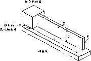
图4显示了按照本发明的MEMS Littrow空腔的布局;Figure 4 shows the layout of a MEMS Littrow cavity according to the present invention;
图5和6分别解释了悬臂和门式框架结构的原理;Figures 5 and 6 explain the principles of cantilever and portal frame structures, respectively;
图7显示了适用于本发明的梳状驱动静电微型激励器;Figure 7 shows a comb drive electrostatic microactuator suitable for use in the present invention;
图8显示了将梳状驱动静电激励器安装到按照本发明的悬挂弯曲上;Figure 8 shows the installation of a comb drive electrostatic actuator to a suspension bend in accordance with the present invention;
图9显示了按照本发明的MEMS可调激光器系统的一个动态模型。Figure 9 shows a dynamic model of a MEMS tunable laser system according to the present invention.
具体实施方式Detailed ways
下面对本发明的可调光学共振器进行描述,其中参照了该可调光学共振器在可调激光器中的应用。The tunable optical resonator of the present invention is described below with reference to the application of the tunable optical resonator in tunable lasers.
同步调节的Littrow空腔的原理Principle of synchronously regulated Littrow cavities
如图1所示的Littrow空腔使用了通过光栅的单通路,旋转该通路来对波长进行调整。该空腔包含具有一个高反射涂覆端面(10)和一个非反射涂覆面(20)的光学放大器(OA)、一个非反射涂覆的透镜(LE)和一个高反射性炫耀反射光栅(G),但也可以使用诸如标准具、柱面透镜和棱镜(未显示)的其它元件来改善光学性能,如下面所述的。The Littrow cavity shown in Figure 1 uses a single pass through a grating, which is rotated to tune the wavelength. The cavity contains an optical amplifier (OA) with a highly reflective coated end face (10) and a non-reflective coated face (20), a non-reflective coated lens (LE) and a highly reflective blazed reflective grating (G ), but other elements such as etalons, cylindrical lenses, and prisms (not shown) can also be used to improve optical performance, as described below.
如图2所示的Littman空腔使用通过光栅(G)的双通路,并需要一个外部的镜子(M),旋转该外部镜子可用于调节。在这种几何结构中可增强光谱纯度,因为在每个往返中会遇到光栅的两次过滤作用。The Littman cavity shown in Figure 2 uses a dual pass through a grating (G) and requires an external mirror (M) that can be rotated for adjustment. Spectral purity is enhanced in this geometry because the filtering action of the grating is encountered twice per round trip.
在Littrow几何结构中,在波长λ处满足纵向共振,对于该波长λ:In Littrow geometry, longitudinal resonance is satisfied at wavelength λ, for which:
λ=2Lc/m (1)λ=2Lc/m (1)
其中Lc是有效的空腔长度(即,空腔的所有部分的光学长度,包含激光器、透镜和空气传播距离),m是模数。where Lc is the effective cavity length (ie, the optical length of all parts of the cavity, including the laser, lens, and air propagation distance), and m is the modulus.
现在,从设置为角度θ的、周期为Λ的炫耀光栅到接近的横梁的第n阶回射发生在这样的波长上:Now, the nth order retroreflection from a blazed grating of period Λ set at an angle θ to an approaching beam occurs at such a wavelength:
λ={2Λ/n}sin(θ) (2)λ={2Λ/n}sin(θ) (2)
为了使共振与光栅反射性中的峰值匹配,应该在最初将空腔长度调整为同时满足等式(1)和(2),此时:To match the resonance to the peak in the reflectivity of the grating, the cavity length should initially be tuned to satisfy both equations (1) and (2), when:
Lc={mΛ/n}sin(θ) (3)Lc={mΛ/n}sin(θ) (3)
在将光栅旋转角度dθ以调节波长的时候,为了维持这个条件,必须将空腔长度改变相应的长度dLc,以使得:When the grating is rotated by the angle dθ to adjust the wavelength, in order to maintain this condition, the cavity length must be changed by the corresponding length dLc, so that:
dLc/dθ={mΛ/n}cos(θ)=Lc/tan(θ) (4)dLc/dθ={mΛ/n}cos(θ)=Lc/tan(θ) (4)
对于第一阶,这可以通过以下方法获得:将光栅安装在沿光栅切向延伸的半径臂上,如图1所示,并选择半径R为:For the first order, this can be obtained by mounting the grating on a radius arm extending tangentially to the grating, as shown in Figure 1, and choosing the radius R as:
R=Lc/sin(θ) (5)R=Lc/sin(θ) (5)
这种构造代表用于同步调节的最佳光栅安装。需要注意,等式5的结果独立于模数m和光栅阶数n,因此最佳旋转中心的半径是唯一的。This configuration represents an optimal grating installation for synchronous regulation. Note that the result of Equation 5 is independent of the modulus m and the grating order n, so the radius of the optimal center of rotation is unique.
对准激光器空腔以便发射激光的处理过程本身是较为复杂的。一种方法包含这样一种激光器(通常还有其它元件),该激光器被安装在弯曲的悬挂物上,允许对线和角进行逐渐地、精确地调整。当实现了激光发射之后,可通过点焊将弯曲固定在一个适当的位置。The process of aligning the laser cavity for lasing is inherently complex. One method involves a laser (and often other components) mounted on a curved suspension, allowing gradual, precise adjustments to lines and angles. Once the laser shot has been achieved, the bend can be fixed in place by spot welding.
可调激光器二极管系统的小型化Miniaturization of Tunable Laser Diode Systems
按照本发明的设备基于一个深蚀刻(即,至少10微米深)的硅微型设计的模拟板,该模拟板提供用于激光器二极管和渐变折射率(GRIN)透镜的对准特征部件,并在弯曲悬挂物上携带电子调节的炫耀光栅以形成Littrow空腔。深蚀刻被描述于Laermer F.和Schilp A.的“Method of anisotropically etching silicon(备向异性地蚀刻硅的方法)”美国专利5 501 893,3月26日(1996)和Gormley C.、Yallup K.、Nevin W.A.、Bhardwaj J.、Ashraf H.、Hugget P.和Blackstone S.的“State of the art deep silicon anisotropicetching on SOI bonded substrates for dielectric isolation andMEMS applications(在用于电介质隔离法和MEMS应用的SOI结合基底上的技术深硅各向异性蚀刻的状态)”关于半导体晶片结合的第五届国际研讨会,电子化学学会秋季会议,夏威夷,美国,10月17-22日(1999)。使用深蚀刻和结合的硅绝缘体(BSOI)来形成该结构可得到较高的机械质量,而使用弯曲支架则可消除对旋转中心轴承的需要。The device according to the present invention is based on a deeply etched (i.e., at least 10 microns deep) silicon micro-engineered dummy board that provides alignment features for the laser diode and graded-index (GRIN) lens, and is Suspensions carry electronically adjusted blazed gratings to form Littrow cavities. Etching back is described in "Method of anisotropically etching silicon" by Laermer F. and Schilp A. US Patent 5 501 893, March 26 (1996) and Gormley C., Yallup K ., Nevin W.A., Bhardwaj J., Ashraf H., Hugget P., and Blackstone S. "State of the art deep silicon anisotropicetching on SOI bonded substrates for dielectric isolation and MEMS applications" State of the Art of Deep Silicon Anisotropic Etching on Bonding Substrates)" Fifth International Symposium on Semiconductor Wafer Bonding, Fall Meeting of the Electrochemical Society, Hawaii, USA, October 17-22 (1999). Forming the structure using deep etch and bonded silicon on insulator (BSOI) results in high mechanical quality, while using a curved standoff eliminates the need for a rotational center bearing.
将安装支架设计成能够最初进行被动调整,之后进行动态波长调节。光栅是深蚀刻结构,它被设置为垂直于晶片平面,并被安装在新型的弹性弯曲悬挂物上,该弹性弯曲悬挂物模仿优选的旋转中心的作用以允许大范围的、无模跳跃的调节。光栅旋转和轴向模同步化的电力控制是通过静电驱动实现的,但也可使用其它的激励方法。The mounting bracket is designed to allow initial passive adjustment followed by dynamic wavelength adjustment. Gratings are deep etched structures that are positioned perpendicular to the plane of the wafer and are mounted on a novel elastically curved suspension that mimics the action of a preferred center of rotation to allow a wide range of adjustment without mode jumps . Electrical control of the grating rotation and axial mode synchronization is achieved by electrostatic actuation, but other actuation methods can also be used.
与传统光栅调节的外腔式激光器二极管相比,本发明的优势在于:调节机构的小型化将允许更高的调节速度,并改善机械和热稳定性,大批量生产技术的使用将使成本降低。使用现有的条纹发射二极管将允许把输出功率维持在与固定波长设备相似的电平上,典型地,这些电平远远超过当前可从VCSEL获得的电平。Advantages of the invention compared to conventional grating-tuned external cavity laser diodes are: the miniaturization of the tuning mechanism will allow higher tuning speeds and improved mechanical and thermal stability, and the use of high-volume production techniques will lead to cost reductions . The use of existing striped emitting diodes will allow maintaining output power at levels similar to fixed wavelength devices, which typically far exceed those currently available from VCSELs.
MEMS可调激光器二极管的构造方案示例Example construction scheme of a MEMS tunable laser diode
一种示例性的MEMS可调激光器系统是基于一种激光器二极管的,该激光器二极管被混合安装在一种硅模拟板上,该硅模拟板是通过对其上结合的硅绝缘体(BSOI)进行深反应离子蚀刻而形成的。这种方法允许在单晶硅中制出厚的、不产生张力的悬挂机械部分。例如,高级硅蚀刻(ASE-Ahalog Devices(贝尔法斯特)的商标),处理过程可以以每分钟约3μm的速率将硅蚀刻到大于350μm的深度,以便使深结构是经济的。同样地,90°±25°的侧面角、大于0.99的各向异性和40∶1的特征方面在此基础上是可能的,这允许生产出高质量的部件。An exemplary MEMS tunable laser system is based on a laser diode that is hybrid mounted on a silicon analog board that is bonded to a silicon-on-insulator (BSOI) by deep Formed by reactive ion etching. This approach allows thick, tension-free suspended mechanical parts to be fabricated in single crystal silicon. For example, Advanced Silicon Etching (ASE - a trade mark of Ahalog Devices (Belfast)), the process can etch silicon to a depth greater than 350 μm at a rate of about 3 μm per minute, so that deep structures are economical. Likewise, flank angles of 90°±25°, anisotropy greater than 0.99 and a characteristic aspect of 40:1 are possible on this basis, which allow the production of high quality parts.
使用这种方法,可以制造图3所示的普通形式的悬挂机械部分。这里,通过深反应离子蚀刻将长度为L、宽度为w的横梁蚀刻到BSOI晶片的结合层(本身厚度为d)中。通过使用(例如)湿酸蚀刻(诸如缓冲的氢氟酸)来蚀刻牺牲的氧化物夹层,从而从相对窄的横梁下面去除氧化物底层。通过适当地选择尺寸和仔细地对蚀刻进行定时,就可以对横梁进行完整地底切,这样,它就可以在晶片的平面内弯曲,同时保持在左手端由相对更大的岛支持。Using this method, a suspension mechanism of the general form shown in Figure 3 can be manufactured. Here, beams of length L and width w are etched by deep reactive ion etching into the bonding layer (itself thickness d) of the BSOI wafer. The oxide underlayer is removed from beneath the relatively narrow beams by etching the sacrificial oxide interlayer using, for example, a wet acid etch such as buffered hydrofluoric acid. With proper size selection and careful timing of the etch, it is possible to fully undercut the beam so that it bends in the plane of the wafer while remaining supported by a relatively larger island at the left-hand end.
通过组合这种性质的制造技术,可以制造更复杂的微型光机电系统。图4显示了按照优选实施例的MEMS Littrow空腔的布局。其尺寸可能约为5mm×6mm:比传统系统的线尺寸大约小10倍。该基底被各向异性地进行蚀刻,以便在形成a≈2μm厚热氧化物层和附带a≈400μm厚结合硅层之前,形成埋λ的对准V凹槽以用于a≈1mm直径1∶4高跨比GRIN透镜。By combining fabrication techniques of this nature, more complex micro-opto-electromechanical systems can be fabricated. Figure 4 shows the layout of a MEMS Littrow cavity according to a preferred embodiment. Its size may be around 5mm x 6mm: about 10 times smaller than the wire size of conventional systems. The substrate is anisotropically etched to form a buried lambda aligned V-groove for a ≈ 1
机械部分和光栅被形成于结合层中。两个深干燥蚀刻的水平面限定了该设备:第一个从右边通过结合层,并画出所有的精密特征部件(光栅、弯曲、静电驱动)的轮廓,而第二个只通过一半,并形成一个平台以便使激光器大致安装在光轴上。使用两个掩模(抗蚀剂和氧化物)将所有的特征部件蚀刻在一起,掩膜之一被通过蚀刻剥去(即去除)一半。然后去除牺牲氧化物。得到的结构被金属化以便增加光栅反射性并允许电连接,然后为激光器模具堆积焊块。The mechanical part and the grating are formed in the bonding layer. Two deeply dry etched levels define the device: the first one passes from the right through the bonding layer and outlines all the delicate features (gratings, bends, electrostatic drives), while the second one passes only halfway through and forms the A platform to allow the laser to be mounted approximately on the optical axis. All the features are etched together using two masks (resist and oxide), one of which is stripped (ie removed) in half by etching. The sacrificial oxide is then removed. The resulting structure is metallized to increase grating reflectivity and allow electrical connections, and then solder bumps are deposited for the laser die.
激光器和透镜支架必须能够进行一次设置调整,以便补偿模具结合误差和透镜直径(OD)和中心同心度误差。该激光器因此被安装在双轴弯曲上,同时透镜对准凹槽提供自由度的第三级。系统的集合包含:将硅模拟板安装在反馈控制的热电冷却器上,以保证空腔的温度稳定性;将激光器模具焊在适当的位置以防备粗糙的、被动对准停止(alignment stop);以及引线接合。The laser and lens holder must be capable of one setup adjustment to compensate for die bonding errors and lens diameter (OD) and center concentricity errors. The laser is thus mounted on a biaxial bend, while the lens alignment groove provides a third degree of freedom. The collection of systems includes: mounting the silicon dummy board on a feedback-controlled thermoelectric cooler for temperature stability of the cavity; soldering the laser die in place to prevent rough, passive alignment stops; and wire bonding.
空腔的对准是通过使用:外部微型操纵器,用于使GRIN透镜沿V-凹槽滑动以达到瞄准(最不关键的操作);静电激励,用于弯曲激光器的支承悬臂并更正位置上的误差(最关键)。横向调整是通过静电梳状驱动执行的,垂直调整是通过平行板驱动执行的。通过使用扫描Fabry-Perot光谱分析器来监视激光器的输出,直到实现了激光发射。然后将透镜和激光器支撑固定在适合的位置。Alignment of the cavity is achieved using: an external micromanipulator to slide the GRIN lens along the V-groove for aiming (least critical operation); electrostatic actuation to bend the laser support cantilever and correct position error (the most critical). Lateral adjustments are performed by electrostatic comb drives and vertical adjustments are performed by parallel plate drives. The output of the laser was monitored by using a scanning Fabry-Perot spectrum analyzer until lasing was achieved. Then fix the lens and laser support in place.
制造在λ≈1.5μm、θ≈45°处反射的第一阶光栅需要0.75μm的特征部件。虽然使用第二阶衍射将使光栅的光谱选择性减半,但第二阶光栅的1.5μm特征部件在直接电子束光刻法的范围之内,而且可通过使用现有的深反应离子蚀刻技术来将得到的图案转移到结合的硅材料上。Fabricating a first-order grating reflecting at λ ≈ 1.5 μm, θ ≈ 45° requires 0.75 μm features. Although the use of second order diffraction would halve the spectral selectivity of the grating, the 1.5 μm features of the second order grating are within the range of direct electron beam lithography and can be achieved by using existing deep reactive ion etching techniques. to transfer the resulting pattern onto the bonded silicon material.
用于对MEMS可调二极管进行同步调节的弯曲支架Bending Holder for Synchronous Adjustment of MEMS Tunable Diodes
用于光栅的弯曲支架具有下列属性,以便进行无模跳跃的调节:Curved supports for gratings have the following properties for adjustment without mode jumps:
1)一个主要的端位移,该端位移模拟围绕优选的旋转中心的旋转,和2)一个次要的线运动,该线运动允许在不改变光栅定向的条件下调整空腔长度。如果我们考虑如图5所示的简单悬臂,那么由点负载F造成的线和角的偏移Δ和θ为:1) a primary end displacement that simulates rotation around a preferred center of rotation, and 2) a secondary wire motion that allows adjustment of the cavity length without changing the orientation of the grating. If we consider a simple cantilever as shown in Figure 5, then the line and angular shifts Δ and θ caused by the point load F are:
Δ=F/kL,θ=F/KA (6)Δ=F/kL, θ=F/KA
其中kL和kA是线和角的刚度,由下面等式给出:where kL and kA are the line and corner stiffnesses given by the following equations:
kL=3EI/L3,kA=2EI/L2 (7)kL=3EI/L 3 , kA=2EI/L 2 (7)
其中E是杨氏模量,I是面积的二阶矩。对于图3所示类型的矩形横梁,I=dw3/12。where E is Young's modulus and I is the second moment of area. For a rectangular beam of the type shown in Figure 3, I=dw 3 /12.
根据等式6和7,线和角偏移之间的关系是:According to Equations 6 and 7, the relationship between line and angular offset is:
Δ=2θL/3 (8)Δ=2θL/3
然而,对于模拟围绕固定点的旋转的端偏移,我们要求However, for end offsets that model rotation about a fixed point, we require
Δ=θL (9)Δ=θL (9)
在等式8和9不同的前提下,旋转中心不能被正确地固定。因此上面的要求1)不能被图5的简单悬臂满足。Under the premise that Equations 8 and 9 are different, the center of rotation cannot be properly fixed. Therefore requirement 1) above cannot be satisfied by the simple cantilever of FIG. 5 .
本发明有利地提供一种复合式弯曲,它允许对线和角位移进行分别调整,以便使上面的条件1)和2)被满足。图6显示了包含连到长度为L1的门式框架的长度为L2的悬臂的复合式弯曲。这里,线和角的端位移Δ和θ2为:The present invention advantageously provides a compound bend which allows separate adjustment of linear and angular displacements so that the above conditions 1) and 2) are satisfied. Figure 6 shows a compound bend involving a cantilever of length L2 attached to a portal frame of length L1. Here, the line and angle end displacements Δ and θ2 are:
Δ=Δ1+Δ2=F{1/k1L+1/k2L},θ2=F{1/k2A}Δ=Δ1+Δ2=F{1/
其中门式框架的线刚度k1L、悬臂的线和角的刚度k2L和k2A由下面的等式给出:where the line stiffness k1L of the portal frame and the line and corner stiffnesses k2L and k2A of the cantilever are given by the following equations:
k1L=24EI1/L13,k2L=3EI2/L23,k2A=2EI2/L22 (11)k1L=24EI1/L1 3 , k2L=3EI2/L2 3 , k2A=2EI2/L2 2 (11)
其中I1和I2分别是门和悬臂弯曲的二阶矩。where I1 and I2 are the second moments of door and cantilever bending, respectively.
对于模拟旋转的端位移,我们要求For end displacements that simulate rotation, we require
Δ=θ2{L1+L2} (12)Δ=θ2{L1+L2}
等式12可以通过认真选择比率α=L1/L2来满足。在I1=I2的特殊情况中(即,对于宽度和深度各处相等的横粱),α是下面三次方程的解:Equation 12 can be satisfied by careful choice of the ratio α=L1/L2. In the special case of I1 = I2 (i.e., for beams of equal width and depth everywhere), α is the solution to the following cubic equation:
α3-12α-4=0 (13)α 3 -12α-4 = 0 (13)
可以找到数字上的解α=3.62。A numerical solution α = 3.62 can be found.
由于这个尺寸比可以容易地从实践中得到,所以我们可以推出:尺寸为L1=3.62L2的复合式弯曲可以因此提供一个调节运动,该调节运动等效于Littrow空腔几何结构的最佳旋转中心的调节运动。Since this size ratio can be easily derived from practice, we can deduce that a compound bend of dimension L1 = 3.62L2 can thus provide an adjustment movement equivalent to the optimal center of rotation for the Littrow cavity geometry adjustment movement.
通过使用梳状驱动静电微型激励器,可以方便地将调节所需的点负载F加到悬臂,如图7中所示[103]。该设备本质上是一个可变电容器,它的一半是固定的,另一半是移动的,其上携带互锁的指状电极。假设有N个内部指状电极和N+1个外部电极,它们之中每一个的深度均为d,并由间隙g分开,当指状物重叠长度X时,可以从平行板电容器近似等式得出该结构的总电容C:The point load F required for adjustment can be conveniently applied to the cantilever by using comb-driven electrostatic microactuators, as shown in Fig. 7 [103]. The device is essentially a variable capacitor with one half fixed and the other moving, carrying interlocking finger electrodes. Assuming there are N inner finger electrodes and N+1 outer electrodes, each of which is of depth d and separated by a gap g, when the fingers overlap by length X, the equation can be approximated from the parallel plate capacitor Finding the total capacitance C of the structure:
C=ε02NXd/g (14)C=ε 0 2NXd/g (14)
其中ε0是自由空间的介电常数。where ε0 is the permittivity of free space.
当电容器被充电到电位V时,可以简单地示出:在该结构的两半之间存在吸引力,该吸引力取决于电容与位置的导数,形式为:When the capacitor is charged to potential V, it can be shown simply that there is an attractive force between the two halves of the structure, which depends on the derivative of capacitance with position in the form:
F=1/2dC/dXV2 (15)F=1/2dC/dXV 2 (15)
由于重叠长度X与x线性相关,所以可得出该力为:Since the overlap length X is linearly related to x, the force can be derived as:
F=(ε0Nd/g)V2 (16)F=(ε 0 Nd/g)V 2 (16)
因此,可通过将梳状驱动静电激励器的移动的一半安装在悬挂弯曲上(如图8所示)来执行对MEMS可调激光器的调节,以便等式16给出的力产生作用而使悬挂偏移。该偏移将与外加的力线性相关。由于等式16中的平方项,该偏移不会随外加的电压线性变化,但是,存在一种替换的电极几何结构,该几何结构包含一个线性的力-电压关系。Therefore, tuning of a MEMS tunable laser can be performed by mounting the moving half of the comb-driven electrostatic actuator on the suspension bend (as shown in Figure 8) so that the force given by Equation 16 acts to cause the suspension offset. This deflection will be linearly related to the applied force. Due to the square term in Equation 16, this offset does not vary linearly with the applied voltage, however, there is an alternative electrode geometry that incorporates a linear force-voltage relationship.
更重要的是,如图8所示地使用第二梳状驱动静电激励器来向门式框架外加另一个点负载允许对光栅的线位置进行独立调整,而不影响其角定向。此第二调节单元因此允许对空腔进行轴向调节,以补偿在将空腔轴向模与光栅反射性峰值对准时造成的初始设置误差。More importantly, applying another point load to the gate frame using a second comb-driven electrostatic actuator as shown in Figure 8 allows independent adjustment of the linear position of the grating without affecting its angular orientation. This second adjustment unit thus allows an axial adjustment of the cavity to compensate for initial setup errors caused in aligning the cavity axial mode with the grating reflectivity peak.
示例设计参数Example Design Parameters
我们可估计一些典型的示例设计参数,如下所示,其中假设弹性悬挂被制成:在携带100μm厚结合层的硅绝缘体晶片中,恒定的横梁宽度为10μm。We can estimate some typical example design parameters as follows, assuming elastic suspensions are made: a constant beam width of 10 μm in a silicon-on-insulator wafer carrying a 100 μm thick bonding layer.
在这种情况中,横梁宽度和深度为w=10μm,d=100μm,面积的二阶矩为I=(100×103)×10-24/12=8.333×10-21m-4,对于硅的杨氏模量为E=1.08×1011N/m2。In this case, the beam width and depth are w=10μm, d=100μm, the second moment of area is I=(100×10 3 )×10 -24 /12=8.333×10 -21 m -4 , for The Young's modulus of silicon is E=1.08×10 11 N/m 2 .
我们可以假设下面任意(但是典型的)长度以用于悬挂部件,即L1=3.62mm,L2=1mm。在这种情况下,光栅旋转中心臂的有效半径R为R=L1+L2=4.62mm,空腔长度为Lc=3.27mm。We can assume the following arbitrary (but typical) lengths for the suspension components, ie L1 = 3.62 mm, L2 = 1 mm. In this case, the effective radius R of the rotating center arm of the grating is R=L1+L2=4.62mm, and the cavity length is Lc=3.27mm.
使用这些参数,就可以从等式11中获得线刚度参数k1L和k2L,为:Using these parameters, the line stiffness parameters k1L and k2L can be obtained from Equation 11 as:
K1L=24×1.08×1011×8.333×10-21/(3.62×10-3)3=0.45N/m,K1L=24×1.08×10 11 ×8.333×10 -21 /(3.62×10 -3 ) 3 =0.45N/m,
K2L=3×1.08×1011×8.333×10-21/(1×10-3)3=2.7N/m (17)K2L=3×1.08×10 11 ×8.333×10 -21 /(1×10 -3 ) 3 =2.7N/m (17)
可以通过使用对于串联弹性弹簧的传统关系式得出复合式悬挂系统的总体线性刚度kL,即:The overall linear stiffness kL of a composite suspension system can be found by using the conventional relationship for series elastic springs, namely:
I/kL=1/k1L+1/k2L=2.6m/N,使得kL=0.385N/m (18)I/kL=1/
调节包含光栅的很小的旋转。对等式2求导,我们得到:Adjustment involves very small rotations of the grating. Deriving Equation 2, we get:
dθ=tan(θ)dλ/λ (19)dθ=tan(θ)dλ/λ (19)
对于工作于λ=1.5μm波长、光栅角被设为θ≈45°的激光器,Δλ=±25nm的调节范围要求光栅旋转通过Δλmax=±0.95°的角度范围。For a laser operating at a wavelength of λ=1.5 μm with the grating angle set to θ≈45°, the adjustment range of Δλ=±25 nm requires the grating to be rotated through the angular range of Δλmax=±0.95°.
通过这个小角度的旋转要求光栅的线切向运动:Rotation through this small angle requires linear tangential motion of the grating:
Δmax=±RΔθmax=4.62×10-3×0.95×π/180≈80×10-6m,或80μm (20)Δmax=±RΔθmax=4.62×10 -3 ×0.95×π/180≈80×10 -6 m, or 80μm (20)
为了通过静电激励获得这个运动,要求该力为:To obtain this motion by electrostatic excitation, the force is required to be:
F=kLΔmax=80×10-6/2.6≈30×10-6N,或30μN (21)F=kLΔmax=80×10 -6 /2.6≈30×10 -6 N, or 30μN (21)
然后可以通过比较等式16和21来获得最大驱动电压:The maximum drive voltage can then be obtained by comparing Equations 16 and 21:
(ε0Nd/g)Vmax2=F=kLΔmax (22)(ε 0 Nd/g)Vmax 2 =F=kLΔmax (22)
使得最大电压为:Such that the maximum voltage is:
Vmax=√{kLΔmax g/ε0Nd} (23)Vmax=√{kLΔmax g/ε 0 Nd} (23)
如果考虑静电激励器包含(假定)宽度为6μm的指状物阵列,其中指状物由g=4μm的间隙分开,那么在总长度为(假定)1mm的激励器中可包含N=50个指状物对。最大电压则为:If one considers that an electrostatic actuator contains an array of (assumed) 6 μm wide fingers, where the fingers are separated by a g = 4 μm gap, then N = 50 fingers can be included in an actuator of (assumed) 1 mm total length. Pair of objects. The maximum voltage is then:
Vmax=√(30×10-6×4×10-6/8.85×10-12×50×100X10-6)≈50V (24)Vmax=√(30×10 -6 ×4×10 -6 /8.85×10 -12 ×50×100X10 -6 )≈50V (24)
在这种设计中还有对驱动电压进行改变的余地,所述的改变是通过以下方式实施的:(1)减小电极间隙,或(2)通过增加电极数量,或(3)通过降低悬挂刚度。There is also room in this design to change the drive voltage by (1) reducing the electrode gap, or (2) by increasing the number of electrodes, or (3) by reducing the overhang stiffness.
我们可如下估计光栅和调节激励器的质量。上面的计算建议了一种具有1mm跨度的梳状电极。在这个跨度上支持光栅和移动指状电极的横梁可具有1mm×50μm的典型尺寸。如果光栅的最大平移为80μm左右,那么梳状指状物的长度必须近似为100μm。假设有50个电板,每个电极宽度为6μm(如上),并假设结构深度为100μm,对于硅的密度为2330kg/m3,那么近似的总移动质量为:We can estimate the quality of the grating and tuning actuator as follows. The above calculations suggest a comb electrode with a span of 1mm. The beams supporting the grating and moving finger electrodes over this span may have typical dimensions of 1 mm x 50 μm. If the maximum translation of the grating is around 80 μm, then the length of the comb fingers must be approximately 100 μm. Assuming 50 electrodes, each electrode width 6µm (as above), and assuming a structure depth of 100µm, for a silicon density of 2330kg/ m3 , the approximate total moving mass is:
m={(10-3×50×10-6)+(50×100×10-6×6×10-6)}×10-4×2330=1.864×10⁻⁸kg (25)m={(10 -3 ×50×10 -6 )+(50×100×10 -6 ×6×10 -6 )}×10 -4 ×2330=1.864×10 -8 kg (25)
对于质量弹簧共振,共振频率ω由下式给出:For mass-spring resonance, the resonant frequency ω is given by:
ω=√(kL/m)=√(0.385/1.864×10-8)=4544rad/s,或725Hz(26)ω=√(kL/m)=√(0.385/1.864×10 -8 )=4544rad/s, or 725Hz(26)
调节时间因此可能超过2ms。这意味着调节的速率可能大幅超过传统的外腔式激光器。The adjustment time may therefore exceed 2 ms. This means that the rate of modulation can be substantially faster than that of conventional external cavity lasers.
在图9中显示出:该支架实际具有三级自由度,因为它有效地包含一个安装在耦合到另一个质量块m2(光栅及其激励器)的线弹簧(轴向调节激励器)上的质量块m1,该质量块m2还具有惯量J2,并被安装在具有线和角刚度的弹簧上。固此,可预测三个特性模。然而,可以根据最低阶模的频率来获得合适的动态行为。It is shown in Fig. 9 that the support actually has three degrees of freedom, since it effectively consists of a wire spring (the actuator for axial adjustment) mounted on a wire spring coupled to the other mass m2 (the grating and its actuator). The mass m1, which also has an inertia J2, is mounted on springs with linear and angular stiffness. Based on this, three characteristic modes can be predicted. However, suitable dynamic behavior can be obtained depending on the frequency of the lowest order mode.
本发明的可调共振器的选择性质还可应用于可调滤光器中,有利地提供无模跳跃的调节。The selective nature of the tunable resonators of the present invention can also be applied in tunable optical filters, advantageously providing mode hopping free tuning.
Claims (11)
Applications Claiming Priority (2)
| Application Number | Priority Date | Filing Date | Title |
|---|---|---|---|
| GBGB0101985.0A GB0101985D0 (en) | 2001-01-25 | 2001-01-25 | Optical component |
| GB0101985.0 | 2001-01-25 |
Publications (2)
| Publication Number | Publication Date |
|---|---|
| CN1502153A CN1502153A (en) | 2004-06-02 |
| CN1237674C true CN1237674C (en) | 2006-01-18 |
Family
ID=9907524
Family Applications (1)
| Application Number | Title | Priority Date | Filing Date |
|---|---|---|---|
| CNB028070445A Expired - Fee Related CN1237674C (en) | 2001-01-25 | 2002-01-23 | Optical element |
Country Status (8)
| Country | Link |
|---|---|
| US (1) | US7116481B2 (en) |
| EP (1) | EP1374355B1 (en) |
| CN (1) | CN1237674C (en) |
| AT (1) | ATE306729T1 (en) |
| CA (1) | CA2437110A1 (en) |
| DE (1) | DE60206610T2 (en) |
| GB (1) | GB0101985D0 (en) |
| WO (1) | WO2002080319A2 (en) |
Families Citing this family (14)
| Publication number | Priority date | Publication date | Assignee | Title |
|---|---|---|---|---|
| GB0316448D0 (en) * | 2003-07-14 | 2003-08-20 | Univ Cambridge Tech | An extended cavity diode laser |
| JP4073886B2 (en) * | 2004-03-30 | 2008-04-09 | アンリツ株式会社 | Variable wavelength light source |
| WO2005100961A2 (en) * | 2004-04-19 | 2005-10-27 | Phoseon Technology, Inc. | Imaging semiconductor strucutures using solid state illumination |
| KR100550141B1 (en) * | 2004-08-09 | 2006-02-08 | 한국전자통신연구원 | Tunable External Resonant Laser Diode Using Variable Optical Deflector |
| US20070280326A1 (en) * | 2005-12-16 | 2007-12-06 | Sioptical, Inc. | External cavity laser in thin SOI with monolithic electronics |
| US7903704B2 (en) * | 2006-06-23 | 2011-03-08 | Pranalytica, Inc. | Tunable quantum cascade lasers and photoacoustic detection of trace gases, TNT, TATP and precursors acetone and hydrogen peroxide |
| WO2009054808A1 (en) * | 2007-10-26 | 2009-04-30 | Agency For Science, Technology And Research | Packaged tunable semiconductor laser structure and its fabrication |
| CN101609959B (en) * | 2008-06-18 | 2013-01-16 | 中国计量科学研究院 | Littrow structure raster outer cavity semiconductor laser device and quasi-synchronization tuning method |
| WO2011000153A1 (en) * | 2009-06-30 | 2011-01-06 | 山东远普光学股份有限公司 | Continuous mode-hop-free grating-tuned external cavity semiconductor laser |
| DE102014201701B4 (en) | 2014-01-30 | 2018-04-05 | Fraunhofer-Gesellschaft zur Förderung der angewandten Forschung e.V. | Microelectromechanical system for tuning lasers |
| ES2910424T3 (en) * | 2017-03-10 | 2022-05-12 | Univ Washington | Methods and systems for measuring and evaluating the stability of medical implants |
| DE102018207783B4 (en) * | 2018-05-17 | 2022-11-10 | Fraunhofer-Gesellschaft zur Förderung der angewandten Forschung e.V. | MEMS array made of MEMS, each with a movable structural element |
| CN109449750B (en) * | 2018-12-14 | 2021-03-02 | 周淼淼 | Laser light path stabilizing device |
| IT201900002013A1 (en) * | 2019-02-12 | 2020-08-12 | Laboratorio Europeo Di Spettroscopie Non Lineari Lens | EXTERNAL CAVITY LASER DEVICE, CORRESPONDING SYSTEM AND PROCEDURE |
Family Cites Families (22)
| Publication number | Priority date | Publication date | Assignee | Title |
|---|---|---|---|---|
| US4229710A (en) * | 1977-10-21 | 1980-10-21 | Itamar Shoshan | Wavelength selector for tunable laser |
| US4589115A (en) * | 1983-09-09 | 1986-05-13 | Xerox Corporation | Wavelength tuning of quantum well heterostructure lasers using an external grating |
| US4942583A (en) * | 1988-06-17 | 1990-07-17 | Hewlett-Packard Company | Misalignment-tolerant, grating-tuned external-cavity laser |
| SE463181B (en) * | 1989-09-07 | 1990-10-15 | Radians Innova Ab | SAID THAT SEASONAL COUNTERFUL RECONCILIATION OF THE RESONANCE FREQUENCY AND Q-VALUE OF AN OPTICAL RESONATOR AND DEVICE BEFORE EXERCISING THE SET |
| FR2664439A1 (en) * | 1990-07-06 | 1992-01-10 | Alsthom Cge Alcatel | Semiconductor laser with external reflector |
| US5263037A (en) * | 1990-08-01 | 1993-11-16 | Hewlett-Packard Company | Optical oscillator sweeper |
| SE467474B (en) * | 1990-09-17 | 1992-07-20 | Radians Innova Ab | positioning device |
| SE468337B (en) * | 1991-05-08 | 1992-12-14 | Radians Innova Ab | SETTING AND ADJUSTING A LASER AND LASER DEVICE WHICH IMPLEMENTS THE SET |
| US5177750A (en) * | 1991-07-30 | 1993-01-05 | Hewlett-Packard Company | Misalignment-tolerant, grating-tuned external-cavity laser with enhanced longitudinal mode selectivity |
| FR2690012B1 (en) * | 1992-04-13 | 1994-07-08 | France Telecom | METHOD FOR ADJUSTING A CONTINUOUSLY TUNABLE LIGHT SOURCE. |
| US5319668A (en) * | 1992-09-30 | 1994-06-07 | New Focus, Inc. | Tuning system for external cavity diode laser |
| DE4241045C1 (en) * | 1992-12-05 | 1994-05-26 | Bosch Gmbh Robert | Process for anisotropic etching of silicon |
| JPH0766482A (en) * | 1993-08-26 | 1995-03-10 | Anritsu Corp | Variable wavelength light source |
| US5579327A (en) * | 1994-06-06 | 1996-11-26 | Anritsu Corporation | External-cavity tunable wavelength light source using semiconductor laser having phase adjustment area |
| FR2724496B1 (en) * | 1994-09-13 | 1996-12-20 | Photonetics | SINGLE-MODE LASER SOURCE TUNABLE IN WAVELENGTH WITH SELF-ALIGNED EXTERNAL CAVITY |
| US5524012A (en) * | 1994-10-27 | 1996-06-04 | New Focus, Inc. | Tunable, multiple frequency laser diode |
| JPH08172233A (en) * | 1994-12-15 | 1996-07-02 | Anritsu Corp | Variable wavelength light source |
| US5739945A (en) * | 1995-09-29 | 1998-04-14 | Tayebati; Parviz | Electrically tunable optical filter utilizing a deformable multi-layer mirror |
| US5771253A (en) * | 1995-10-13 | 1998-06-23 | The Board Of Trustees Of The Leland Stanford Junior University | High performance micromechanical tunable verticle cavity surface emitting laser |
| US5629951A (en) * | 1995-10-13 | 1997-05-13 | Chang-Hasnain; Constance J. | Electrostatically-controlled cantilever apparatus for continuous tuning of the resonance wavelength of a fabry-perot cavity |
| JPH10341057A (en) * | 1997-06-06 | 1998-12-22 | Ando Electric Co Ltd | External resonator type wavelength-variable semiconductor laser optical source and wavelength variable method therefor |
| US6847661B2 (en) * | 1999-09-20 | 2005-01-25 | Iolon, Inc. | Tunable laser with microactuator |
-
2001
- 2001-01-25 GB GBGB0101985.0A patent/GB0101985D0/en not_active Ceased
-
2002
- 2002-01-23 EP EP02715549A patent/EP1374355B1/en not_active Expired - Lifetime
- 2002-01-23 CA CA002437110A patent/CA2437110A1/en not_active Abandoned
- 2002-01-23 DE DE60206610T patent/DE60206610T2/en not_active Expired - Lifetime
- 2002-01-23 WO PCT/GB2002/000267 patent/WO2002080319A2/en not_active Ceased
- 2002-01-23 AT AT02715549T patent/ATE306729T1/en not_active IP Right Cessation
- 2002-01-23 US US10/470,392 patent/US7116481B2/en not_active Expired - Fee Related
- 2002-01-23 CN CNB028070445A patent/CN1237674C/en not_active Expired - Fee Related
Also Published As
| Publication number | Publication date |
|---|---|
| GB0101985D0 (en) | 2001-03-14 |
| WO2002080319A2 (en) | 2002-10-10 |
| EP1374355B1 (en) | 2005-10-12 |
| WO2002080319A3 (en) | 2003-10-16 |
| US20040151214A1 (en) | 2004-08-05 |
| DE60206610T2 (en) | 2006-05-11 |
| EP1374355A2 (en) | 2004-01-02 |
| CN1502153A (en) | 2004-06-02 |
| CA2437110A1 (en) | 2002-10-10 |
| US7116481B2 (en) | 2006-10-03 |
| ATE306729T1 (en) | 2005-10-15 |
| DE60206610D1 (en) | 2005-11-17 |
Similar Documents
| Publication | Publication Date | Title |
|---|---|---|
| CN1237674C (en) | Optical element | |
| US10288870B2 (en) | Wavelength tunable MEMS-Fabry Perot filter | |
| US6661830B1 (en) | Tunable optically-pumped semiconductor laser including a polarizing resonator mirror | |
| CN103633558B (en) | Adopt the wideband adjustable outside cavity gas laser of small-sized MEMS mirror | |
| IT201600079604A1 (en) | OSCILLATING STRUCTURE WITH PIEZOELECTRIC IMPLEMENTATION, SYSTEM AND MANUFACTURING METHOD | |
| US7217587B2 (en) | MEMS scanning mirror with trenched surface and tapered comb teeth for reducing inertia and deformation | |
| CN1285034A (en) | Microelectromechanically, tunable, confocel, VCSEL and fabry-perot filter | |
| JP2005031115A (en) | Tunable optical filter | |
| US6721098B2 (en) | Triple electrode MOEMS tunable filter and fabrication process therefor | |
| JP2009524229A (en) | Tunable laser | |
| JP2697353B2 (en) | Fabry-Perot type variable wavelength filter and method of manufacturing the same | |
| JP2005223111A (en) | Tunable laser | |
| US11673799B2 (en) | Method of processing a wafer for manufacturing an oscillating structure such as a micro-mirror | |
| JP2005031326A (en) | Light filter | |
| EP3032662B1 (en) | Variable-wavelength light source | |
| JPH06188497A (en) | Wavelength-tunable semiconductor light emitting device | |
| JP2005243756A (en) | External cavity type tunable semiconductor laser device | |
| US20060166444A1 (en) | MEMS scanning mirror with trenched surface and i-beam like cross-section for reducing inertia and deformation | |
| JP2005183871A (en) | Surface emitting laser | |
| Liu et al. | MEMS widely tunable lasers for WDM system applications | |
| CN120933622A (en) | Tunable filter based on MEMS micro-mirror | |
| Liu et al. | Micromachined MEMS Tunable Laser for WDM System Applications | |
| CN1700540A (en) | External resonator semiconductor laser and manufacturing method thereof | |
| Zhang et al. | Widely tunable lasers using MEMS gratings and mirrors | |
| HK1229893B (en) | Wavelength tunable mems-fabry perot filter |
Legal Events
| Date | Code | Title | Description |
|---|---|---|---|
| C06 | Publication | ||
| PB01 | Publication | ||
| C10 | Entry into substantive examination | ||
| SE01 | Entry into force of request for substantive examination | ||
| C14 | Grant of patent or utility model | ||
| GR01 | Patent grant | ||
| ASS | Succession or assignment of patent right |
Owner name: L.M. ERICSSON CO., LTD. Free format text: FORMER OWNER: M(DGP1) CO., LTD. Effective date: 20070209 Owner name: M(DGP1) CO., LTD. Free format text: FORMER OWNER: MARCONI UK INTELLECTUAL PROP Effective date: 20070209 |
|
| C41 | Transfer of patent application or patent right or utility model | ||
| TR01 | Transfer of patent right |
Effective date of registration: 20070209 Address after: Stockholm, Sweden Patentee after: ERICSSON AB Address before: Coventry, United Kingdom Patentee before: M (DGP1) Ltd. Effective date of registration: 20070209 Address after: Coventry, United Kingdom Patentee after: M (DGP1) Ltd. Address before: Coventry, United Kingdom Patentee before: MARCONI UK INTELLECTUAL PROPERTY Ltd. |
|
| CF01 | Termination of patent right due to non-payment of annual fee |
Granted publication date: 20060118 Termination date: 20160123 |
|
| EXPY | Termination of patent right or utility model |