CN1299954C - Container with air intake mechanism - Google Patents

Container with air intake mechanism Download PDF

Info

Publication number
CN1299954C
CN1299954C CNB038053845A CN03805384A CN1299954C CN 1299954 C CN1299954 C CN 1299954C CN B038053845 A CNB038053845 A CN B038053845A CN 03805384 A CN03805384 A CN 03805384A CN 1299954 C CN1299954 C CN 1299954C
Authority
CN
China
Prior art keywords
container
air
liquid
pass passage
along
Prior art date
Legal status (The legal status is an assumption and is not a legal conclusion. Google has not performed a legal analysis and makes no representation as to the accuracy of the status listed.)
Expired - Fee Related
Application number
CNB038053845A
Other languages
Chinese (zh)
Other versions
CN1639012A (en
Inventor
山名茂
Current Assignee (The listed assignees may be inaccurate. Google has not performed a legal analysis and makes no representation or warranty as to the accuracy of the list.)
Shan Mingmao
Aicello Chemical Co Ltd
Original Assignee
Aicello Chemical Co Ltd
Priority date (The priority date is an assumption and is not a legal conclusion. Google has not performed a legal analysis and makes no representation as to the accuracy of the date listed.)
Filing date
Publication date
Application filed by Aicello Chemical Co Ltd filed Critical Aicello Chemical Co Ltd
Publication of CN1639012A publication Critical patent/CN1639012A/en
Application granted granted Critical
Publication of CN1299954C publication Critical patent/CN1299954C/en
Anticipated expiration legal-status Critical
Expired - Fee Related legal-status Critical Current

Links

Images

Classifications

    • BPERFORMING OPERATIONS; TRANSPORTING
    • B65CONVEYING; PACKING; STORING; HANDLING THIN OR FILAMENTARY MATERIAL
    • B65DCONTAINERS FOR STORAGE OR TRANSPORT OF ARTICLES OR MATERIALS, e.g. BAGS, BARRELS, BOTTLES, BOXES, CANS, CARTONS, CRATES, DRUMS, JARS, TANKS, HOPPERS, FORWARDING CONTAINERS; ACCESSORIES, CLOSURES, OR FITTINGS THEREFOR; PACKAGING ELEMENTS; PACKAGES
    • B65D25/00Details of other kinds or types of rigid or semi-rigid containers
    • B65D25/38Devices for discharging contents
    • B65D25/40Nozzles or spouts
    • BPERFORMING OPERATIONS; TRANSPORTING
    • B65CONVEYING; PACKING; STORING; HANDLING THIN OR FILAMENTARY MATERIAL
    • B65DCONTAINERS FOR STORAGE OR TRANSPORT OF ARTICLES OR MATERIALS, e.g. BAGS, BARRELS, BOTTLES, BOXES, CANS, CARTONS, CRATES, DRUMS, JARS, TANKS, HOPPERS, FORWARDING CONTAINERS; ACCESSORIES, CLOSURES, OR FITTINGS THEREFOR; PACKAGING ELEMENTS; PACKAGES
    • B65D1/00Rigid or semi-rigid containers having bodies formed in one piece, e.g. by casting metallic material, by moulding plastics, by blowing vitreous material, by throwing ceramic material, by moulding pulped fibrous material or by deep-drawing operations performed on sheet material
    • B65D1/12Cans, casks, barrels, or drums
    • B65D1/20Cans, casks, barrels, or drums characterised by location or arrangement of filling or discharge apertures
    • BPERFORMING OPERATIONS; TRANSPORTING
    • B65CONVEYING; PACKING; STORING; HANDLING THIN OR FILAMENTARY MATERIAL
    • B65DCONTAINERS FOR STORAGE OR TRANSPORT OF ARTICLES OR MATERIALS, e.g. BAGS, BARRELS, BOTTLES, BOXES, CANS, CARTONS, CRATES, DRUMS, JARS, TANKS, HOPPERS, FORWARDING CONTAINERS; ACCESSORIES, CLOSURES, OR FITTINGS THEREFOR; PACKAGING ELEMENTS; PACKAGES
    • B65D25/00Details of other kinds or types of rigid or semi-rigid containers
    • B65D25/28Handles
    • BPERFORMING OPERATIONS; TRANSPORTING
    • B65CONVEYING; PACKING; STORING; HANDLING THIN OR FILAMENTARY MATERIAL
    • B65DCONTAINERS FOR STORAGE OR TRANSPORT OF ARTICLES OR MATERIALS, e.g. BAGS, BARRELS, BOTTLES, BOXES, CANS, CARTONS, CRATES, DRUMS, JARS, TANKS, HOPPERS, FORWARDING CONTAINERS; ACCESSORIES, CLOSURES, OR FITTINGS THEREFOR; PACKAGING ELEMENTS; PACKAGES
    • B65D25/00Details of other kinds or types of rigid or semi-rigid containers
    • B65D25/38Devices for discharging contents
    • BPERFORMING OPERATIONS; TRANSPORTING
    • B65CONVEYING; PACKING; STORING; HANDLING THIN OR FILAMENTARY MATERIAL
    • B65DCONTAINERS FOR STORAGE OR TRANSPORT OF ARTICLES OR MATERIALS, e.g. BAGS, BARRELS, BOTTLES, BOXES, CANS, CARTONS, CRATES, DRUMS, JARS, TANKS, HOPPERS, FORWARDING CONTAINERS; ACCESSORIES, CLOSURES, OR FITTINGS THEREFOR; PACKAGING ELEMENTS; PACKAGES
    • B65D25/00Details of other kinds or types of rigid or semi-rigid containers
    • B65D25/38Devices for discharging contents
    • B65D25/40Nozzles or spouts
    • B65D25/42Integral or attached nozzles or spouts
    • YGENERAL TAGGING OF NEW TECHNOLOGICAL DEVELOPMENTS; GENERAL TAGGING OF CROSS-SECTIONAL TECHNOLOGIES SPANNING OVER SEVERAL SECTIONS OF THE IPC; TECHNICAL SUBJECTS COVERED BY FORMER USPC CROSS-REFERENCE ART COLLECTIONS [XRACs] AND DIGESTS
    • Y10TECHNICAL SUBJECTS COVERED BY FORMER USPC
    • Y10STECHNICAL SUBJECTS COVERED BY FORMER USPC CROSS-REFERENCE ART COLLECTIONS [XRACs] AND DIGESTS
    • Y10S215/00Bottles and jars
    • Y10S215/902Vent

Landscapes

  • Engineering & Computer Science (AREA)
  • Mechanical Engineering (AREA)
  • Ceramic Engineering (AREA)
  • Details Of Rigid Or Semi-Rigid Containers (AREA)
  • Containers Having Bodies Formed In One Piece (AREA)
  • Containers And Packaging Bodies Having A Special Means To Remove Contents (AREA)
  • Catching Or Destruction (AREA)
  • External Artificial Organs (AREA)
  • Vacuum Packaging (AREA)
  • Closures For Containers (AREA)
  • Blow-Moulding Or Thermoforming Of Plastics Or The Like (AREA)

Abstract

一种用于储存液体的单口容器,当其内部液体排放时能够防止流动的脉动和控制排放速度维持在大致恒定而不管容器内部液体存量多少,其中吹塑模制部分(23)形成在容器口部的容器主体侧面部分上;从吹塑模制部分(23)侧壁延伸到容器主体的上部的空间的缩小部分(24)、排放口(31)和空气通道(11)是通过收缩缩小部分而形成的;空气通道具有如此长度:使通过空气通道(11)供应的空气直接释放在内部液体中;并且排放口(31)和空气口(25)二者均形成在缩小部分(24)处。

Figure 03805384

A single-mouth container for storing liquid, which is capable of preventing flow pulsation and controlling the discharge speed to be approximately constant when the liquid inside the container is discharged, regardless of the amount of liquid stored inside the container, wherein a blow molded part (23) is formed on the side part of the container body at the container mouth; a narrowing part (24), a discharge port (31) and an air channel (11) extending from the side wall of the blow molded part (23) to the space above the container body are formed by shrinking the narrowing part; the air channel has such a length that air supplied through the air channel (11) is directly released into the internal liquid; and both the discharge port (31) and the air port (25) are formed at the narrowing part (24).

Figure 03805384

Description

Container with intake mechanism
Technical field
The present invention relates to the container of storaging liquid, relate more specifically to have a kind of container of storaging liquid of function, this function is when liquid is emitted in remaining on internal tank, though its internal liquid storage what, it is constant and can prevent to pulse when it is mobile all to keep liquid to emit the speed constant.
Background technology
As this quasi-tradition container, for example, have as shown in figure 22 the container of two openings or as shown in figure 23 (U.S. Patent No. 5,340,000) have the container of intake mechanism.
Twoport container shown in Figure 22 has such shortcoming, promptly must open two openings and internal liquid be flowed out smoothly and unlikely generation pulsation when liquid flows out from container.Another shortcoming is that twoport type container is owing to its shape and two lids of each container requirement have the cost rising problem that itself involves.On the contrary, container shown in Figure 23 has only an opening and makes easily.But such single port container has a bigger air supply pipe, and this pipe also is used as handle, so that design-calculated freely is restricted.
Also have, these traditional containers have common characteristic, and promptly the air of supply container is directly to enter interior of the container and do not pass through internal liquid.The intake mechanism of form can be realized the outflow that liquid is very level and smooth like this, because do not have when internal liquid is replaced by air because the resistance that internal liquid causes.But, the liquid velocity of outflow changes with the internal liquid surface elevation.In other words, liquid was discharged with higher speed in the initial period of discharging, and this moment, a large amount of internal liquids was retained in the container.Mass rate of emission reduces and reduces gradually along with the internal liquid surplus.
Correspondingly, need make it be in steady state by the angle of inclination control mass rate of emission of adjusting container along with the minimizing of internal liquid.
Summary of the invention
Problem described above can solve with first aspect present invention, and it is one to have the container of intake mechanism, and it comprises: opening is greater than the blown-moulding part of container finish, and the blown-moulding of a position forms below container finish by using for it; Dwindling partial sum forms by dwindling at blown-moulding container body lateral parts partly at the discharge side that dwindles in the part; And air by-pass passage extends and is connected to the inner upper space of container body from being positioned at the blown-moulding partial sidewall of dwindling part top, and air by-pass passage has the length of so lacking: make by the air by-pass passage air supplied to be directly released in the internal liquid of container when internal liquid is discharged.
Being characterized as of the second aspect present invention of container dwindled part, discharge side and air scoop and formed by dwindling the container body lateral parts of partly locating at blown-moulding simultaneously.
In addition, for improving the availability of container, discharge side has and the about same axis of container finish, and has and the about same size and dimension of container finish.
Description of drawings
Fig. 1 shows the state of emission testing.
Fig. 2 comprises according to the front elevation of the first embodiment container, planar view with along the section-drawing of A-A line.
Fig. 3 is the amplification profile according to the first embodiment opening portion.
Fig. 4 is along B-B line section-drawing among Fig. 3.
Fig. 5 is along C-C line section-drawing among Fig. 3.
Fig. 6 is the amplification profile according to first embodiment opening portion when discharging internal liquid.
Fig. 7 comprises front elevation, lateral plan and the planar view according to the another kind of container of second embodiment.
Fig. 8 is the amplification profile according to the second embodiment opening portion.
Fig. 9 is along D-D line section-drawing among Fig. 8.
Figure 10 is along E-E line section-drawing among Fig. 8.
Figure 11 comprises front elevation, lateral plan and the planar view of another kind of container again according to the 3rd embodiment.
Figure 12 comprises front elevation, lateral plan and the planar view according to the another kind of container of the 4th embodiment.
Figure 13 is the amplification profile according to the 4th embodiment opening portion.
Figure 14 is along F-F line section-drawing among Figure 13.
Figure 15 is along G-G line section-drawing among Figure 13.
Figure 16 is along H-H line section-drawing among Figure 13.
Figure 17 is the opening portion amplification profile, shows the emissions status according to the 4th embodiment.
Figure 18 comprises front elevation, lateral plan and the planar view according to the another kind of container of the 5th embodiment.
Figure 19 is according to the 5th embodiment opening portion amplification profile.
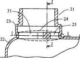
Figure 20 is along I-I line section-drawing among Figure 19.
Figure 21 is along J-J line section-drawing among Figure 19.
Figure 22 shows traditional two open containers.
Figure 23 shows to have the conventional container of intake mechanism.
Figure 24 is for showing the diagram of curves of measurement point and fluid discharge time relationship.
In these figure, reference number is as follows: the 10th, and bottle, the 11st, air by-pass passage, the 21st, container finish, the 22nd, container body, the 23rd, the blown-moulding part, the 24th, dwindle part, the 25th, air scoop, the 31st, discharge side, the 35th, fluid and 40 is air.
The specific embodiment
According to the present invention, the container with intake mechanism comprises: opening is greater than the blown-moulding part 23 of container finish 21, and the blown-moulding of a position forms below container finish 21 by using for it; Dwindle part 24 and dwindle by container body 22 lateral parts and form in blown-moulding part 23 at the discharge side 31 that dwindles 24 li of parts; And air by-pass passage 11 is from being positioned at the inner upper space that blown-moulding part 23 sidewalls that dwindle part 24 tops extend and be connected to container body 22, and air by-pass passage 11 has so short length: make by air by-pass passage 11 air supplied 40 to be directly released in the internal liquid 35 of container when internal liquid 35 discharges.
Being characterized as of the second aspect present invention of container dwindled part 24, discharge side 31 and air scoop 25 and formed by container body 22 lateral parts that dwindle at blown-moulding part 23 places simultaneously.
In addition, for improving the availability of container, discharge side 31 has and container finish 21 about same axis, and has and container finish 21 about same size and dimensions.
Carrying out before following examples, utilize bottle 10 as shown in Figure 1 to carry out pre-determined test, so that decision relation between internal liquid 35 (being water) and the discharge velocity relevant in being retained in container with air by-pass passage 11 length.When liquid 35 when bottle 10 is discharged by bottleneck, air 40 is fed to bottle 10 by air by-pass passage 11 by the arrow line indication.
Shown in Figure 1A, 1B and 1C, the three types of bottles 10 with different air by-pass passage 11 length are prepared as test.The length of the air by-pass passage 11 among Figure 1A is set to 20-30mm, and this is generally the minimum length that guarantees not have pulsating flow when internal liquid 35 is discharged; And in Figure 1B, air path length approximately is half of height of bottle 10; In Fig. 1 C, the length of air by-pass passage 11 approximates the height of bottle 10 greatly.
Each bottle 10 almost completely full of liquid 35 and then the head that is placed as shown in Figure 1A, 1B and 1C of bottle 10 get a foothold to go up with beginning discharge liquid 35.The surface of liquid 35 reduces along with the discharge process of internal liquid 35.Mass rate of emission on each height of the liquid surface that 1 to 6 measurement point is represented in the survey map 1.Mass rate of emission is measured from 10 li dischargings of bottle required time according to about 200ml (milliliter) liquid.Test results is presented in the following table.Each A, B in table, C be illustrated respectively in shown in Figure 1A, 1B and the 1C the length of air by-pass passage 11.
Measurement point Drain time (second/200 milliliters)
A B C
1 10.9 6.5 5.0
2 10.9 6.7 5.5
3 10.8 6.6 6.1
4 10.7 7.2 6.9
5 10.8 8.5 8.5
6 10.9 11.0 10.7
The result is presented in the diagram of curves of Figure 24 in the table.Abscissa among the figure is represented measurement point and ordinate is represented 200 milliliters drain time.Curve A is to use the drain time of the air by-pass passage 11 that shows in Figure 1A, curve B is to use the drain time of the air by-pass passage 11 that shows in Figure 1B, and curve C is to use the drain time of the air by-pass passage 11 that shows in Fig. 1 C.
From these results, can recognize that front edge when air by-pass passage 11 when liquid surface is following, can keep the specific mass rate of emission that is determined by air by-pass passage 11 length.And when the front edge of air by-pass passage 11 is emerged liquid surface, mass rate of emission and the proportional variation of liquid surface height.
In the length of air by-pass passage 11 is that the front edge of air by-pass passage is in below liquid 35 surfaces forever in the bottle 10 of the shortest Figure 1A, and mass rate of emission is controlled and controlled, and demonstrates approximately constant mass rate of emission and irrelevant with the liquid surface height.As long as the front edge of air by-pass passage is in more than the liquid surface, the discharging of liquid 35 will be extremely steady.Though can observe slight pulsation when the front edge of air by-pass passage is in the surface of liquid 35 when following, such slight pulsations can not throw into question in actual applications.
Below preferred embodiment will be described, but the scope of the invention will be not limited to these embodiment.
First embodiment
Fig. 2 A, 2B and 2C show respectively according to the front elevation of the first embodiment container, planar view with along the section-drawing of A-A line, and Fig. 3 is the opening portion amplification profile.Fig. 4 is the section-drawing along Fig. 3 center line B-B, and Fig. 5 is along C-C line section-drawing among Fig. 3.Fig. 6 is the amplification profile of opening portion when discharging internal liquid according to first scheme.In first embodiment, blown-moulding part 23 is formed on below the spiral shell mosquito part.
Being supplied to the air 40 of container by air by-pass passage 11 is to discharge in the internal liquid in being retained in container.According to such mechanism, the mass rate of emission of liquid can keep constant and no matter the in-to-in liquid stock how.
Second embodiment
Fig. 7 A, 7B and 7C show respectively according to the front elevation of the another kind of container of second embodiment, lateral plan and planar view, and Fig. 8 is the amplification profile of its opening portion.In Fig. 7 C, label 26 is wherein porose convex ridges that lead to air by-pass passage 11.Fig. 9 is along D-D line section-drawing among Fig. 8, and Figure 10 is along E-E line section-drawing among Fig. 8.In this second embodiment, blown-moulding part 23 comprises the threaded portion that forms by blow mold process.In addition, the two is communicated with the air by-pass passage 11 in convex ridge 26 and blown-moulding part 23 and handle base partial interior space, and handle is arranged on the top of container body.
The 3rd embodiment
Figure 11 A, 11B and 11C show front elevation, lateral plan and the planar view of the another kind of container again of the 3rd embodiment respectively.Short and compact dimensions makes air by-pass passage 11 can not only be applied to smooth square container in air by-pass passage 11 length of 26 li of convex ridges, also can be used for circle bilge type container.
The 4th embodiment
Figure 12 A, 12B and 12C show respectively according to the front elevation of the another kind of container of the 4th embodiment, planar view and lateral plan.Figure 13 is the amplification profile of its opening portion, and Figure 14 is along F-F line section-drawing among Figure 13.Figure 15 is along G-G line section-drawing among Figure 13, and Figure 16 is along H-H line section-drawing among Figure 13.Figure 17 is the opening portion amplification profile, shows the emissions status according to the 4th embodiment.In the 4th embodiment, air by-pass passage and air scoop 25 form as the inner space of blown-moulding part 23.
The 5th embodiment
Figure 18 A, 18B and 18C show respectively according to the front elevation of the another kind of container of the 5th embodiment, planar view and lateral plan, and Figure 19 is its opening portion amplification profile.Figure 20 is along I-I line section-drawing among Figure 19, and Figure 21 is along J-J line section-drawing among Figure 19.In this embodiment, intake mechanism is compact dimensionally a lot, makes intake mechanism can more easily not only be applied to smooth square container and also can be used for circle bilge type container.But, distinctive outshot is arranged on the inside of opening in this type intake mechanism, makes it might cause difficulty when inserting liquid perfusion nozzle in container.
When internal liquid discharges, can realize that on the single port container pulse free flows.Mass rate of emission can remain constant and no matter the storage of its internal liquid in container how, makes it not need to control mass rate of emission by the angle of inclination that changes container.The intake mechanism compact dimensions can freely design container.
When making container of the present invention, can adopt traditional molding molding process, so that do not need to use special molding machine or mould.There is not larger-size outshot in inside at oral area, therefore difficulty can not take place when perfusion fluid in container or insertion liquid filling pump.

Claims (3)

1.一种具有空气进气机构的容器,包括:1. A container with an air intake mechanism, comprising: 吹塑模制部分(23),其开口大于容器口部(21),它通过利用在容器口部下面位置上的吹塑模制形成;a blow molded portion (23) having an opening larger than the container mouth (21), which is formed by utilizing blow molding at a position below the container mouth; 缩小部分(24)和在缩小部分(24)中的排放口(31),它们通过在吹塑模制部分(23)的容器主体(22)侧面部分缩小而形成;和a narrowed portion (24) and a discharge opening (31) in the narrowed portion (24), which are formed by partially narrowing the side of the container body (22) of the blow-molded portion (23); and 空气通道(11),它从位于缩小部分上方处的吹塑模制部分(23)侧壁延伸并且连接到容器主体(22)的内部上部空间,空气通道(11)具有如此之短的长度:使通过空气通道(11)供应的空气当内部液体排出时直接释放在容器内的内部液体中。The air channel (11), which extends from the side wall of the blow-molded part (23) at the place above the narrowing part and connects to the inner headspace of the container body (22), has such a short length that: The air supplied through the air channel (11) is caused to be released directly into the inner liquid in the container when the inner liquid is discharged. 2.按照权利要求1所述的具有空气进气机构的容器,其特征在于,缩小部分(24)、排出口(31)和空气口(25)同时通过收缩吹塑模制部分(23)的容器主体(22)侧面部分而形成。2. The container with an air inlet mechanism according to claim 1, characterized in that the narrowing part (24), the discharge port (31) and the air port (25) pass through the shrinkage of the blow molding part (23) simultaneously. The side part of the container body (22) is formed. 3.按照权利要求1或2所述的具有空气进气机构的容器,其特征在于,排放口(31)具有与容器口部(21)同样的轴线和与容器口部(21)同样的尺寸及形状。3. The container according to claim 1 or 2, characterized in that the discharge opening (31) has the same axis as the container mouth (21) and the same size as the container mouth (21) and shape.
CNB038053845A 2002-03-05 2003-02-28 Container with air intake mechanism Expired - Fee Related CN1299954C (en)

Applications Claiming Priority (4)

Application Number Priority Date Filing Date Title
JP2002058129 2002-03-05
JP58129/2002 2002-03-05
JP205866/2002 2002-07-15
JP2002205866A JP3394769B1 (en) 2002-03-05 2002-07-15 Container with intake mechanism

Publications (2)

Publication Number Publication Date
CN1639012A CN1639012A (en) 2005-07-13
CN1299954C true CN1299954C (en) 2007-02-14

Family

ID=26625700

Family Applications (1)

Application Number Title Priority Date Filing Date
CNB038053845A Expired - Fee Related CN1299954C (en) 2002-03-05 2003-02-28 Container with air intake mechanism

Country Status (7)

Country Link
US (1) US7331490B2 (en)
EP (1) EP1491451B1 (en)
JP (1) JP3394769B1 (en)
CN (1) CN1299954C (en)
AT (1) ATE465950T1 (en)
DE (1) DE60332336D1 (en)
WO (1) WO2003074372A1 (en)

Families Citing this family (11)

* Cited by examiner, † Cited by third party
Publication number Priority date Publication date Assignee Title
KR100558766B1 (en) * 2005-07-18 2006-03-10 조경희 Beverage container with air inflow passage
KR101480003B1 (en) * 2008-03-31 2015-01-09 삼성디스플레이 주식회사 Method of driving electrophoretic display
DE102008030076A1 (en) * 2008-06-25 2009-12-31 Hörmansdörfer, Gerd Compound material pack for liquid or viscous filling has at least one flow guide incorporated into pouring nozzle
USD747968S1 (en) 2011-11-15 2016-01-26 Husqvarna Ab Bottle
CN103387081A (en) * 2012-05-08 2013-11-13 天心工业股份有限公司 Spilling prevention device for liquid container
US10518947B2 (en) * 2016-11-04 2019-12-31 Valvoline Licensing & Intellectual Property LLC Controlled pour bottle
US10829277B2 (en) * 2018-02-13 2020-11-10 Stackcan Llc Container vent, dispenser and holding system
IT201800002815A1 (en) * 2018-02-19 2019-08-19 Umberto Nenna PLASTIC CONTAINER FOR LIQUIDS WITH ANTI-SPLASH DEVICE
USD870549S1 (en) 2018-12-17 2019-12-24 Kost Usa, Inc. Bottle
US12408756B1 (en) 2022-05-27 2025-09-09 Series International, Llc Stacking chair with removable back
CN115108125B (en) * 2022-08-26 2022-11-22 山东京阳科技股份有限公司 Fuel oil barrel suitable for ocean transportation

Citations (4)

* Cited by examiner, † Cited by third party
Publication number Priority date Publication date Assignee Title
WO1987001677A1 (en) * 1985-09-16 1987-03-26 Goodall Donald T Liquid dispenser
US5340000A (en) * 1993-07-13 1994-08-23 Ring Can Corporation Vented plastic bottle
JPH10230980A (en) * 1997-02-14 1998-09-02 Sekisui Seikei Kogyo Kk Container provided with suction air bypass
JP2000334814A (en) * 1999-05-31 2000-12-05 Sekisui Seikei Ltd Blow-molded container having pulse preventing port part and its molding method

Family Cites Families (10)

* Cited by examiner, † Cited by third party
Publication number Priority date Publication date Assignee Title
US3308997A (en) * 1965-10-11 1967-03-14 Crystal Preforming And Packagi Plastic jug
US4105148A (en) * 1975-02-03 1978-08-08 Sterling Drug, Inc. Self-venting spout
EP0058624B1 (en) * 1981-02-17 1985-06-19 Seprosy Societe Europeenne Pour La Transformation Des Produits De Synthese Process of making a jug of plastic material with controlled pouring
US4804119A (en) 1985-12-06 1989-02-14 Goodall Donald T Liquid dispenser
US4856685A (en) * 1988-02-02 1989-08-15 Mlw Corporation Dispensing container
US5123575A (en) * 1991-08-09 1992-06-23 Li Hofman Y Multi-chamber container having two interior partitions
EP0858952A1 (en) * 1997-02-13 1998-08-19 FELIX BÖTTCHER GmbH & Co. Container for transporting and storing liquids
US6029858A (en) * 1998-05-01 2000-02-29 Srokose; John S. Jug and method
DE10051336C1 (en) * 2000-04-14 2002-02-28 Ingolf Morgenroth Two-stage pourer for liquid containers
US6494350B2 (en) * 2000-12-29 2002-12-17 Scott Kelley Self-measuring dispensing container

Patent Citations (4)

* Cited by examiner, † Cited by third party
Publication number Priority date Publication date Assignee Title
WO1987001677A1 (en) * 1985-09-16 1987-03-26 Goodall Donald T Liquid dispenser
US5340000A (en) * 1993-07-13 1994-08-23 Ring Can Corporation Vented plastic bottle
JPH10230980A (en) * 1997-02-14 1998-09-02 Sekisui Seikei Kogyo Kk Container provided with suction air bypass
JP2000334814A (en) * 1999-05-31 2000-12-05 Sekisui Seikei Ltd Blow-molded container having pulse preventing port part and its molding method

Also Published As

Publication number Publication date
CN1639012A (en) 2005-07-13
US7331490B2 (en) 2008-02-19
EP1491451A1 (en) 2004-12-29
DE60332336D1 (en) 2010-06-10
US20050092780A1 (en) 2005-05-05
WO2003074372A1 (en) 2003-09-12
EP1491451A8 (en) 2005-04-27
HK1080811A1 (en) 2006-05-04
JP3394769B1 (en) 2003-04-07
ATE465950T1 (en) 2010-05-15
JP2003327252A (en) 2003-11-19
EP1491451A4 (en) 2007-07-25
EP1491451B1 (en) 2010-04-28

Similar Documents

Publication Publication Date Title
CN1123398C (en) Upright and Inverted Trigger Liquid Dispenser Container
CN1179867C (en) dispensing pump
CN1230702A (en) Plastic container and method and apparatus for supplying photographic processing chemical material therewith
CN1440349A (en) Spout assembly having plurality of fluid passages
CN1639012A (en) Container with intake mechanism
CN1236334A (en) Manual Spray Devices for Liquids
US3845787A (en) Liquor supply for an automated liquor dispensing system
US20120305125A1 (en) Funnel to counter out-splashing of a fluid being poured through it
CN1089646C (en) Container with manual pump
US7401971B2 (en) Method for stirring liquid
CN2434462Y (en) Water spraying vacuum pump with square nozzle
CN108342281A (en) Stirring device for producing Maotai-flavor liquor by fermentation method
HK1080811B (en) Container with intake mechanism
WO2015135503A1 (en) Fluid guiding apparatus
CN1086963C (en) Spray container
CN1251820A (en) Hand jetting pump
CN1921944A (en) Metering a dose of sample liquid
CN211800916U (en) Quantitative liquid supplementing device
JP2003054606A (en) Straightening plug
CN2744517Y (en) Marking instrument
JPH09118338A (en) Bottle with air suction port, and its auxiliary port
JP4955330B2 (en) Nozzle tip for dispensing equipment
CN221836741U (en) A feeding device to prevent liquid material from splashing out
JP3350668B2 (en) Container with air intake mechanism
CN221592160U (en) Self-ventilation honeycomb duct

Legal Events

Date Code Title Description
C06 Publication
PB01 Publication
C10 Entry into substantive examination
SE01 Entry into force of request for substantive examination
REG Reference to a national code

Ref country code: HK

Ref legal event code: DE

Ref document number: 1080811

Country of ref document: HK

C14 Grant of patent or utility model
GR01 Patent grant
C56 Change in the name or address of the patentee

Owner name: AICELLO COMPANY

Free format text: FORMER NAME: YAMANA SHIGERU

CP01 Change in the name or title of a patent holder

Address after: Aichi

Patentee after: AICELLO CHEMICAL CO.

Patentee after: Shan Mingmao

Address before: Aichi

Patentee before: Aicello Chemical Co., Ltd.

Patentee before: Shan Mingmao

CF01 Termination of patent right due to non-payment of annual fee

Granted publication date: 20070214

Termination date: 20170228

CF01 Termination of patent right due to non-payment of annual fee