CN201068942Y - Overdrive clutch of electric bicycle - Google Patents
Overdrive clutch of electric bicycle Download PDFInfo
- Publication number
- CN201068942Y CN201068942Y CNU2007201116922U CN200720111692U CN201068942Y CN 201068942 Y CN201068942 Y CN 201068942Y CN U2007201116922 U CNU2007201116922 U CN U2007201116922U CN 200720111692 U CN200720111692 U CN 200720111692U CN 201068942 Y CN201068942 Y CN 201068942Y
- Authority
- CN
- China
- Prior art keywords
- ratchet
- cylindrical
- ring
- ratchet ring
- seat
- Prior art date
- Legal status (The legal status is an assumption and is not a legal conclusion. Google has not performed a legal analysis and makes no representation as to the accuracy of the status listed.)
- Expired - Fee Related
Links
- 230000002093 peripheral effect Effects 0.000 claims abstract 2
Images

Landscapes
- Connection Of Motors, Electrical Generators, Mechanical Devices, And The Like (AREA)
Abstract
电动自行车超越离合器,其特征在于有一个安装在轴上的圆柱形棘爪座,圆柱形棘爪座的外周壁上制有半圆形的凹槽和直线斜口,在半圆形凹槽和直线斜口中安装相配合的棘爪,在棘爪座外有圆柱形棘齿圈,圆柱形棘齿圈内壁中制有棘齿,棘齿与棘爪相接触。本技术方案利用棘爪、棘齿的作用达到离合器的目的,当电机工作时,棘爪卡入外棘齿圈内与棘齿相接触,外棘齿圈与车轮相连,电机和棘爪座等带动外棘齿圈及车轮旋转作功;而当电机停止工作时,棘爪与外棘齿圈自动分离,外棘齿圈与车轮继续转动,使车继续行驶一段路程,节省电能。
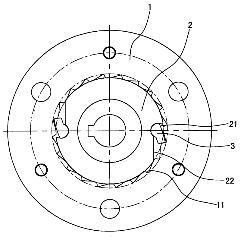
The electric bicycle overrunning clutch is characterized in that there is a cylindrical ratchet seat installed on the shaft, and a semicircular groove and a linear bevel are formed on the outer peripheral wall of the cylindrical ratchet seat. Matching ratchets are installed in the linear slanted mouth, and a cylindrical ratchet ring is arranged outside the ratchet seat. A ratchet is formed in the inner wall of the cylindrical ratchet ring, and the ratchet contacts with the ratchet. This technical solution uses the function of the pawl and ratchet to achieve the purpose of the clutch. When the motor is working, the pawl is inserted into the outer ratchet ring to contact the ratchet, the outer ratchet ring is connected with the wheel, the motor and the pawl seat, etc. Drive the outer ratchet ring and the wheel to rotate to do work; and when the motor stops working, the pawl and the outer ratchet ring are automatically separated, and the outer ratchet ring and the wheel continue to rotate, so that the car can continue to travel for a certain distance and save electric energy.
Description
Claims (1)
Priority Applications (1)
| Application Number | Priority Date | Filing Date | Title |
|---|---|---|---|
| CNU2007201116922U CN201068942Y (en) | 2007-07-06 | 2007-07-06 | Overdrive clutch of electric bicycle |
Applications Claiming Priority (1)
| Application Number | Priority Date | Filing Date | Title |
|---|---|---|---|
| CNU2007201116922U CN201068942Y (en) | 2007-07-06 | 2007-07-06 | Overdrive clutch of electric bicycle |
Publications (1)
| Publication Number | Publication Date |
|---|---|
| CN201068942Y true CN201068942Y (en) | 2008-06-04 |
Family
ID=39490325
Family Applications (1)
| Application Number | Title | Priority Date | Filing Date |
|---|---|---|---|
| CNU2007201116922U Expired - Fee Related CN201068942Y (en) | 2007-07-06 | 2007-07-06 | Overdrive clutch of electric bicycle |
Country Status (1)
| Country | Link |
|---|---|
| CN (1) | CN201068942Y (en) |
Cited By (1)
| Publication number | Priority date | Publication date | Assignee | Title |
|---|---|---|---|---|
| CN108884883A (en) * | 2016-03-31 | 2018-11-23 | 罗特技术组件公司 | A kind of flywheel mechanism |
-
2007
- 2007-07-06 CN CNU2007201116922U patent/CN201068942Y/en not_active Expired - Fee Related
Cited By (2)
| Publication number | Priority date | Publication date | Assignee | Title |
|---|---|---|---|---|
| CN108884883A (en) * | 2016-03-31 | 2018-11-23 | 罗特技术组件公司 | A kind of flywheel mechanism |
| CN108884883B (en) * | 2016-03-31 | 2020-07-28 | 罗特技术组件公司 | a flywheel mechanism |
Similar Documents
| Publication | Publication Date | Title |
|---|---|---|
| CN203438142U (en) | Universal converter of electric screw driver | |
| WO2010105484A1 (en) | Transmission mechanism being arranged at left or right end of the motor vehicle back wheel | |
| CN201068942Y (en) | Overdrive clutch of electric bicycle | |
| CN106655613B (en) | Two-stage speed reduction bearing type hub motor for two-wheeled electric vehicle | |
| CN204250286U (en) | A kind of middle dual-power driving device for intelligent bicycle | |
| CN201369632Y (en) | Reduction type brushless motor for electric vehicle | |
| WO2010083703A1 (en) | Coaxial integral drive mechanism for electric motor vehicle having centrifugal clutch and overrunning coupler | |
| CN202484132U (en) | Unidirectional gear structure of electromobile | |
| CN112078715B (en) | Intelligent mid-mounted motor | |
| CN105370823A (en) | Speed regulation device | |
| CN202165285U (en) | Novel pedaling kinetic energy-powered fan | |
| CN201162643Y (en) | Portable hand-shaking inflator | |
| CN209700869U (en) | The electric vehicle of Multi-stage transmission output mechanism and application Multi-stage transmission output mechanism | |
| CN201723588U (en) | A New One-way Bearing Structure | |
| CN201041219Y (en) | Cycloidal planetary gear speed reducer possessing input axis system unloading structure | |
| CN202674099U (en) | Silent overrunning clutch for bicycles | |
| CN201300710Y (en) | Vehicle hybrid-power mechanical coupling device | |
| CN202507854U (en) | Axle semiaxle | |
| CN201304961Y (en) | Novel automobile steering wheel lock | |
| CN217108046U (en) | Planetary gear reduction box | |
| CN202298150U (en) | Connecting structure of direct drive motor for high vehicle | |
| CN201521787U (en) | lever mechanism | |
| CN201075742Y (en) | Stator slice of electric vehicle wheel hub electrical machine | |
| CN201287813Y (en) | Dual-power trochal disk for electric bicycle | |
| CN214081083U (en) | An adjustable Z-direction height integrated universal body positioning pin |
Legal Events
| Date | Code | Title | Description |
|---|---|---|---|
| C14 | Grant of patent or utility model | ||
| GR01 | Patent grant | ||
| ASS | Succession or assignment of patent right |
Owner name: XINDAYANG ELECTROMECHANICAL GROUP CO.,LTD. Free format text: FORMER OWNER: BAO WENGUANG Effective date: 20090605 |
|
| C41 | Transfer of patent application or patent right or utility model | ||
| TR01 | Transfer of patent right |
Effective date of registration: 20090605 Address after: Taizhou, Huangyan Economic Development Zone, Zhejiang Province, 8 new Arch Road, zip code: 318020 Patentee after: Jiangsu University Address before: Taizhou City, Zhejiang Province Economic Development Zone Huangyan New Road No. 8 Taizhou xindayang arch Group Co. Ltd., zip code: 318020 Patentee before: Bao Wenguang |
|
| C17 | Cessation of patent right | ||
| CF01 | Termination of patent right due to non-payment of annual fee |
Granted publication date: 20080604 Termination date: 20120706 |