CN201722256U - Sewage treating pond - Google Patents
Sewage treating pond Download PDFInfo
- Publication number
- CN201722256U CN201722256U CN2010202322454U CN201020232245U CN201722256U CN 201722256 U CN201722256 U CN 201722256U CN 2010202322454 U CN2010202322454 U CN 2010202322454U CN 201020232245 U CN201020232245 U CN 201020232245U CN 201722256 U CN201722256 U CN 201722256U
- Authority
- CN
- China
- Prior art keywords
- zone
- treatment tank
- barrier structure
- screen cloth
- area
- Prior art date
- Legal status (The legal status is an assumption and is not a legal conclusion. Google has not performed a legal analysis and makes no representation as to the accuracy of the status listed.)
- Expired - Lifetime
Links
- 239000010865 sewage Substances 0.000 title claims abstract description 73
- XLYOFNOQVPJJNP-UHFFFAOYSA-N water Substances O XLYOFNOQVPJJNP-UHFFFAOYSA-N 0.000 claims abstract description 37
- 230000004888 barrier function Effects 0.000 claims abstract description 33
- 239000000945 filler Substances 0.000 claims abstract description 18
- 239000010802 sludge Substances 0.000 claims abstract description 8
- 239000007788 liquid Substances 0.000 claims description 4
- 230000000694 effects Effects 0.000 claims description 2
- 239000004744 fabric Substances 0.000 claims 9
- 241000108664 Nitrobacteria Species 0.000 claims 1
- 238000010992 reflux Methods 0.000 claims 1
- 230000000903 blocking effect Effects 0.000 abstract description 9
- 238000005273 aeration Methods 0.000 abstract description 6
- 239000000725 suspension Substances 0.000 abstract 1
- 238000000034 method Methods 0.000 description 13
- IJGRMHOSHXDMSA-UHFFFAOYSA-N Atomic nitrogen Chemical compound N#N IJGRMHOSHXDMSA-UHFFFAOYSA-N 0.000 description 12
- 230000001546 nitrifying effect Effects 0.000 description 8
- 241000894006 Bacteria Species 0.000 description 6
- 229910052757 nitrogen Inorganic materials 0.000 description 6
- 230000008569 process Effects 0.000 description 5
- 125000006850 spacer group Chemical group 0.000 description 5
- 238000010586 diagram Methods 0.000 description 3
- OAICVXFJPJFONN-UHFFFAOYSA-N Phosphorus Chemical compound [P] OAICVXFJPJFONN-UHFFFAOYSA-N 0.000 description 2
- 229910052698 phosphorus Inorganic materials 0.000 description 2
- 239000011574 phosphorus Substances 0.000 description 2
- 238000004062 sedimentation Methods 0.000 description 2
- 101000824979 Homo sapiens Transcription factor Sp4 Proteins 0.000 description 1
- JVMRPSJZNHXORP-UHFFFAOYSA-N ON=O.ON=O.ON=O.N Chemical compound ON=O.ON=O.ON=O.N JVMRPSJZNHXORP-UHFFFAOYSA-N 0.000 description 1
- 102100022446 Transcription factor Sp4 Human genes 0.000 description 1
- XKMRRTOUMJRJIA-UHFFFAOYSA-N ammonia nh3 Chemical compound N.N XKMRRTOUMJRJIA-UHFFFAOYSA-N 0.000 description 1
- QVGXLLKOCUKJST-UHFFFAOYSA-N atomic oxygen Chemical compound [O] QVGXLLKOCUKJST-UHFFFAOYSA-N 0.000 description 1
- 238000006243 chemical reaction Methods 0.000 description 1
- 238000010924 continuous production Methods 0.000 description 1
- 230000007547 defect Effects 0.000 description 1
- 230000006872 improvement Effects 0.000 description 1
- 239000010842 industrial wastewater Substances 0.000 description 1
- 238000012986 modification Methods 0.000 description 1
- 230000004048 modification Effects 0.000 description 1
- GQPLMRYTRLFLPF-UHFFFAOYSA-N nitrous oxide Inorganic materials [O-][N+]#N GQPLMRYTRLFLPF-UHFFFAOYSA-N 0.000 description 1
- 239000005416 organic matter Substances 0.000 description 1
- 229910052760 oxygen Inorganic materials 0.000 description 1
- 239000001301 oxygen Substances 0.000 description 1
- 238000012163 sequencing technique Methods 0.000 description 1
- 239000000126 substance Substances 0.000 description 1
Images


Classifications
-
- Y—GENERAL TAGGING OF NEW TECHNOLOGICAL DEVELOPMENTS; GENERAL TAGGING OF CROSS-SECTIONAL TECHNOLOGIES SPANNING OVER SEVERAL SECTIONS OF THE IPC; TECHNICAL SUBJECTS COVERED BY FORMER USPC CROSS-REFERENCE ART COLLECTIONS [XRACs] AND DIGESTS
- Y02—TECHNOLOGIES OR APPLICATIONS FOR MITIGATION OR ADAPTATION AGAINST CLIMATE CHANGE
- Y02W—CLIMATE CHANGE MITIGATION TECHNOLOGIES RELATED TO WASTEWATER TREATMENT OR WASTE MANAGEMENT
- Y02W10/00—Technologies for wastewater treatment
- Y02W10/10—Biological treatment of water, waste water, or sewage
Landscapes
- Purification Treatments By Anaerobic Or Anaerobic And Aerobic Bacteria Or Animals (AREA)
Abstract
本实用新型公开了一种污水处理池,其包括厌氧区、缺氧区、好氧区与出水区,好氧区对应的池底设置有曝气系统,好氧区内填充有轻质悬浮填料,厌氧区与缺氧区之间设置有第一阻隔结构,该第一阻隔结构的底部设置有自厌氧区向缺氧区输入污水的第一过水洞;缺氧区与好氧区之间设置有第二阻隔结构,该第二阻隔结构下部设有第二过水洞,第二阻隔结构上间隔的设有拦截筛网,第二过水洞分布在拦截筛网之间,拦截筛网上设置有防止污泥沉降的搅拌器;好氧区与出水区之间设置有间隔筛网。本实用新型对污水处理池进行科学合理的改进,并填充一定数量的填料,对污水进行循环连续的处理,使污水处理池能够连续工作,提高了脱氮率,降低了处理污水的成本。
The utility model discloses a sewage treatment pool, which comprises an anaerobic area, anoxic area, an aerobic area and a water outlet area, an aeration system is arranged at the bottom of the pool corresponding to the aerobic area, and the aerobic area is filled with light suspension Filling, a first barrier structure is set between the anaerobic zone and the anoxic zone, and the bottom of the first barrier structure is provided with a first water hole for inputting sewage from the anaerobic zone to the anoxic zone; the anoxic zone and the aerobic zone A second blocking structure is provided between the zones, and a second water hole is provided at the lower part of the second blocking structure, and intercepting screens are arranged at intervals on the second blocking structure, and the second water holes are distributed between the intercepting screens, An agitator to prevent sludge from settling is arranged on the blocking screen; an interval screen is arranged between the aerobic area and the water outlet area. The utility model scientifically and rationally improves the sewage treatment pool, fills a certain amount of fillers, and continuously treats the sewage in a cycle, so that the sewage treatment pool can work continuously, improves the denitrification rate, and reduces the cost of sewage treatment.
Description
技术领域technical field
本实用新型涉及有机污水处理技术领域,尤其涉及一种处理小区生活污水与工业废水的污水处理池。The utility model relates to the technical field of organic sewage treatment, in particular to a sewage treatment pool for treating residential sewage and industrial waste water.
背景技术Background technique
SBR法是序批式活性污泥法的简称,其工艺具有结构简单、布局紧凑、占地少、处理效果稳定、操作灵活等多项优点。近年来SBR法得到了长足的发展,但其池容量利用率较低,设备闲置时间较长,并且难以连续工作。传统或经典SBR法处理的污水去除氨氮的平均值仅为30%,同时由于SBR池体积偏小,造成污水停留时间短、曝气时间短,导致COD、NH3-N、BOD5不能稳定达标排放,并且现有的传统或经典SBR工艺中往往没有生物脱氮的要求,出水水质难以达到一级排放标准。由此可见,现有技术有待于更进一步改进和发展。The SBR method is the abbreviation of the sequencing batch activated sludge method. Its process has many advantages such as simple structure, compact layout, less land occupation, stable treatment effect and flexible operation. In recent years, the SBR method has been greatly developed, but its pool capacity utilization rate is low, the equipment idle time is long, and it is difficult to work continuously. The average value of the removal of ammonia nitrogen from the sewage treated by the traditional or classic SBR method is only 30%. At the same time, due to the small volume of the SBR tank, the residence time of the sewage is short and the aeration time is short, resulting in COD, NH 3 -N, and BOD 5 cannot be stably up to the standard discharge, and the existing traditional or classic SBR process often does not require biological denitrification, and the effluent quality is difficult to meet the first-level discharge standard. This shows that the prior art needs further improvement and development.
实用新型内容Utility model content
本实用新型为解决上述现有技术中的缺陷提供一种污水处理池,对现有技术中的污水处理池进行科学合理的改进,以提高其脱氮性能,降低其闲置率。The utility model provides a sewage treatment pool to solve the above-mentioned defects in the prior art, and scientifically and rationally improves the sewage treatment pool in the prior art to improve its denitrification performance and reduce its idle rate.
为解决上述技术问题,本实用新型方案包括:In order to solve the above-mentioned technical problems, the utility model scheme includes:
一种污水处理池,其包括厌氧区、缺氧区、好氧区与出水区,其中,好氧区对应的池底设置有曝气系统,好氧区内填充有轻质悬浮填料,厌氧区与缺氧区之间设置有第一阻隔结构,该第一阻隔结构的底部设置有自厌氧区向缺氧区输入污水的第一过水洞;缺氧区与好氧区之间设置有第二阻隔结构,该第二阻隔结构下部设有第二过水洞,第二阻隔结构上间隔的设有拦截筛网,第二过水洞分布在拦截筛网之间,拦截筛网上设置有防止污泥沉降的搅拌器;好氧区与出水区之间设置有间隔筛网。A sewage treatment pond, which includes an anaerobic zone, anoxic zone, an aerobic zone, and an outlet zone, wherein an aeration system is provided at the bottom of the tank corresponding to the aerobic zone, and the aerobic zone is filled with light suspended fillers, and the anaerobic zone A first barrier structure is set between the oxygen zone and the anoxic zone, and the bottom of the first barrier structure is provided with a first water hole for inputting sewage from the anaerobic zone to the anoxic zone; between the anoxic zone and the aerobic zone A second barrier structure is provided, and the second barrier structure is provided with a second water hole at the bottom, and intercepting screens are arranged at intervals on the second barrier structure, and the second water holes are distributed between the intercepting screens, and the intercepting screens An agitator is provided to prevent sludge from settling; an interval screen is provided between the aerobic zone and the water outlet zone.
所述的污水处理池,其中,上述第二阻隔结构为阻隔板或阻隔墙,拦截筛网间隔的布置在第二阻隔结构上,每个拦截筛网均自阻隔板或阻隔墙的上沿竖直延伸至下沿;第二过水洞布置在拦截筛网之间的阻隔板或阻隔墙的下部。The above-mentioned sewage treatment tank, wherein, the above-mentioned second barrier structure is a barrier plate or a barrier wall, and the intercepting screens are arranged on the second barrier structure at intervals, and each intercepting screen is vertical from the upper edge of the barrier plate or the barrier wall. Extend straight to the lower edge; the second water hole is arranged at the lower part of the barrier plate or the barrier wall between the interception screens.
所述的污水处理池,其中,上述间隔筛网向两侧延伸至池侧壁,向上延伸至池上沿,向下延伸至池底。Said sewage treatment tank, wherein, the above-mentioned interval screen extends to both sides to the side wall of the pool, extends upward to the upper edge of the pool, and extends downward to the bottom of the pool.
所述的污水处理池,其中,上述出水区内设置有排泥器,在出水区末端设置用于将出水去内硝化液与活性污泥回流到缺氧区的混合液回流泵。Said sewage treatment tank, wherein, a mud discharger is provided in the water outlet area, and a mixed liquid return pump for returning the effluent to the anoxic area is provided at the end of the water outlet area.
所述的污水处理池,其中,上述出水区内设置有至少一个推流器,缺氧区紧靠池侧壁的两端分别设置有至少一个推流器。Said sewage treatment tank, wherein at least one flow pusher is arranged in the water outlet area, and at least one flow pusher is respectively arranged at both ends of the anoxic area close to the side wall of the pool.
所述的污水处理池,其中,上述污水处理池的截面为圆形。Said sewage treatment pool, wherein, the cross section of said sewage treatment pool is circular.
所述的污水处理池,其中,上述间隔筛网内设置有能硝化截留硝化细菌的填料。Said sewage treatment tank, wherein, said spacer screens are provided with fillers capable of nitrifying and retaining nitrifying bacteria.
所述的污水处理池在低水位对污水进行处理,并从高水位向池中连续冲入污水,使污水处理形成连续的过程,提高了污水处理的效率。The sewage treatment pool treats sewage at a low water level, and continuously pours sewage into the pool from a high water level, so that the sewage treatment forms a continuous process and improves the efficiency of sewage treatment.
本实用新型提供的一种污水处理池,将污水处理池设计为截面为圆形,整体接近于圆柱的池型,在池中分割为厌氧区、缺氧区、好氧区与出水区,好氧区填充污水处理填料,好氧区的池底设置有曝气系统,缺氧区设置搅拌器,防止污泥沉降,污水处理池能连续处理污水,提高了污水处理效率,降低了其闲置率,并且在好氧区内填充可截留世代时间长的硝化细菌的生物填料,提高了脱氮的效率,经过本实用新型处理的污水达到一级排放标准,脱氮率可达到90%以上。The utility model provides a sewage treatment pool, the sewage treatment pool is designed as a circular cross-section, the overall shape is close to a cylindrical pool, and the pool is divided into anaerobic area, anoxic area, aerobic area and water outlet area. The aerobic area is filled with sewage treatment filler, the bottom of the aerobic area is equipped with an aeration system, and the anoxic area is equipped with agitators to prevent sludge from settling. The sewage treatment tank can continuously treat sewage, which improves the efficiency of sewage treatment and reduces its idle time. The aerobic area is filled with biological fillers that can retain nitrifying bacteria with a long generation time, which improves the efficiency of denitrification. The sewage treated by the utility model reaches the first-class discharge standard, and the denitrification rate can reach more than 90%.
附图说明Description of drawings
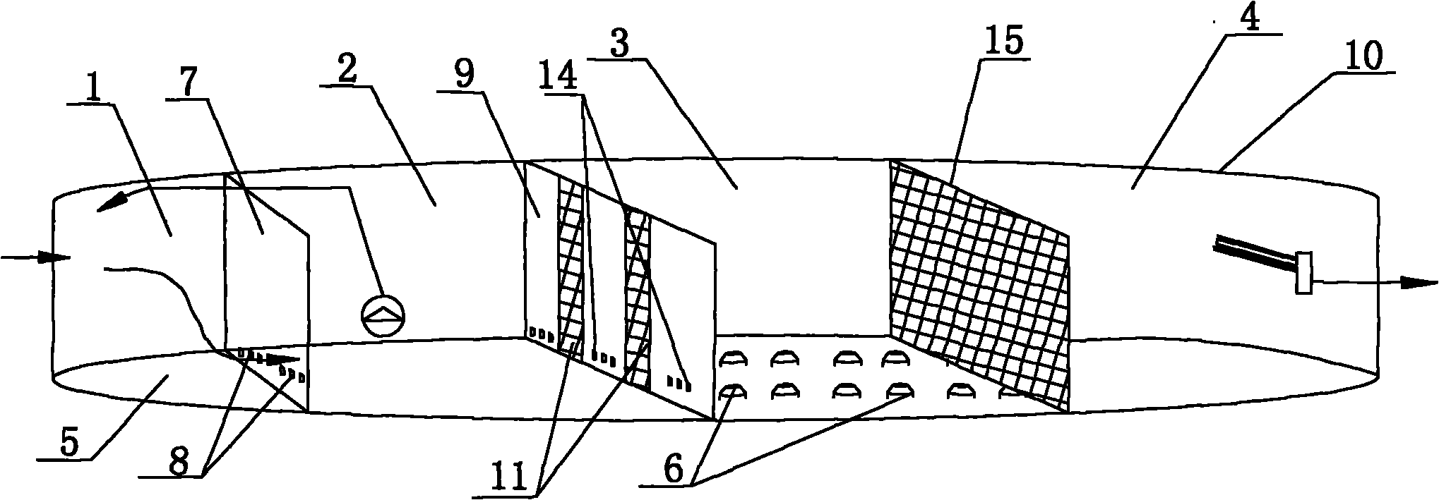
图1是本实用新型中污水处理池截去一池侧壁的立体结构示意图;Fig. 1 is the schematic diagram of the three-dimensional structure of a pond side wall cut off in the sewage treatment pond in the utility model;
图2是本实用新型中污水处理池的俯视结构示意图;Fig. 2 is the top view structure schematic diagram of the sewage treatment tank in the utility model;
图3是本实用新型中污水处理池的纵剖结构示意图。Fig. 3 is a schematic diagram of the longitudinal section structure of the sewage treatment tank in the utility model.
具体实施方式Detailed ways
本实用新型提供了一种污水处理池,为了使本实用新型的目的、技术方案以及优点更清楚、明确,以下将结合附图与实施例,对本实用新型进一步详细说明。The utility model provides a sewage treatment pool. In order to make the purpose, technical solution and advantages of the utility model clearer and clearer, the utility model will be further described in detail below in conjunction with the accompanying drawings and embodiments.
本实用新型提供的一种污水处理池,将污水处理池分割为厌氧区、缺氧区、好氧区与出水区,其中缺氧区设置搅拌器,好氧区填充污水处理填料,污水处理池沉淀滗水时,仍能连续通水,提高了污水处理效率,并且污水连续经过各个区域,使污水中有机物与填料充分接触,提高了脱氮的效率。如图1所示的,污水处理池包括厌氧区1、缺氧区2、好氧区3与出水区4,好氧区2对应的池底5设置有曝气系统6,好氧区3内填充有轻质悬浮填料,厌氧区1与缺氧区2之间设置有第一阻隔结构7,该第一阻隔结构7的底部设置有用于自厌氧区1向缺氧区2输入污水的第一过水洞8;缺氧区2与好氧区3之间设置有第二阻隔结构9,该第二阻隔结构9下部与池侧壁10相接之处设置有第二过水洞11,第二阻隔结构9上间隔的设有拦截筛网14,第二过水洞11分布在拦截筛网14之间,拦截筛网14上设置有防止污泥沉降的搅拌器;好氧区3与出水区4之间设置有间隔筛网15,该间隔筛网15内设置有用于处理污水的填充料,该填充料一般采用SPR-1型填料;通过上述描述可知,在好氧区中填充轻质悬浮填料,即可截留世代时间长的硝化细菌的填料,缺氧区中设有搅拌器,污水中的氮素在好氧区被转化为亚硝化氮,在缺氧区被转化为氮气,而污水中含有的磷素在厌氧区通过化学方法除去,本实用新型提高了脱氮的效率。The utility model provides a sewage treatment pool, which divides the sewage treatment pool into anaerobic area, anoxic area, aerobic area and water outlet area, wherein the anoxic area is equipped with agitator, and the aerobic area is filled with sewage treatment fillers. When the pool is settling and decanting, water can still flow continuously, which improves the efficiency of sewage treatment, and the sewage passes through various areas continuously, so that the organic matter in the sewage can fully contact with the filler, and the efficiency of denitrification is improved. As shown in Figure 1, the sewage treatment tank includes
为了更进一步的提高本实用新型的性能,如图1、图2与图3所示的,第二阻隔结构9为阻隔板或阻隔墙,拦截筛网14上间隔的布置在第二阻隔结构9上,每个拦截筛网14均自阻隔板或阻隔墙的上沿竖直延伸至下沿;第二过水洞11布置在拦截筛网14之间的阻隔板或阻隔墙的下部。并且间隔筛网15向两侧延伸至池侧壁10,向上延伸至池上沿,向下延伸至池底5。尤其是出水区4内设置有排泥器16,在出水区末端设置用于将出水去内硝化液与活性污泥回流到缺氧区的混合液回流泵17。上述出水区内设置有至少一个推流器,缺氧区紧靠池侧壁的两端分别设置有至少一个推流器18、推流器19。本实用新型中污水处理池的水平横截面为圆形,当然也可以根据需要将污水处理池的水平横截面设置为方形、椭圆形或其他形状。上述间隔筛网15内设置有能硝化截留硝化细菌的填料。由上描述可知,填料停留在筛网结构内,污水连续在污水处理池中流动,延长了污水停留时间与曝气时间,提高了脱氮的效率,降低了设备闲置率。In order to further improve the performance of the present utility model, as shown in Fig. 1, Fig. 2 and Fig. 3, the
为了更详细的描述本实用新型,现以日处理5万吨生活污水为例进行说明。污水水质的基本参数为:COD:600mg/l;BOD5:200mg/l;TN:50mg/l;NH4-N:40mg/l;SS:300mg/l。将上述污水通过SBR法在污水处理池中运行,推流器17、推流器18与推流器19提供动力,形成顺时针或逆时针沿接近于圆柱形的污水处理池循环流动,使污水一次通过厌氧区1、缺氧区2、好氧区3与出水区4,在厌氧区1内进行化学反应除去其中的磷素,在好氧区3内通过硝化细菌将污水内的氮素形成亚硝化氮,在缺氧区2内通过反硝化细菌将亚硝化氮转化为氮气并释放,在出水区4内进行沉淀滗水,由于第一阻隔结构7与第二阻隔结构9的阻隔作用,所以在进行沉淀滗水时,污水仍持续进入厌氧区1内,形成连续工作流程,污水的具体流动过程如图1与图2中箭头所指示的。由于SBR法的运行流程现有技术已经非常成熟,在此不再赘述。上述污水通过本实用新型处理后的排放水标准如下表1所示的。通过表1所示的可知,本实用新型提高了脱氮率,并且大幅度降低了COD、BOD5、TN与SS等值,提高了处理水的排放标准。In order to describe the utility model in more detail, now take the daily treatment of 50,000 tons of domestic sewage as an example for illustration. The basic parameters of sewage water quality are: COD: 600mg/l; BOD 5 : 200mg/l; TN: 50mg/l; NH4-N: 40mg/l; SS: 300mg/l. The above-mentioned sewage is run in the sewage treatment tank by the SBR method, and the
表1Table 1
综上所述,本实用新型提供的一种污水处理池,通过对现有技术中污水处理池的结构进行改进,并在相关区域内填充相应的填料,对污水进行循环连续的处理,使污水处理池能够连续工作,降低了设备闲置率;污水在污水处理池内循环流动,提高了污水在有效区域内的停留时间,提高了脱氮率,提高了填料的利用率,降低了处理污水的成本,是现有技术的极大进步。To sum up, the utility model provides a kind of sewage treatment pool, by improving the structure of the sewage treatment pool in the prior art, and filling the corresponding filler in the relevant area, the sewage is treated continuously in a cycle, so that the sewage The treatment tank can work continuously, which reduces the idle rate of equipment; the sewage circulates in the sewage treatment tank, which increases the residence time of sewage in the effective area, improves the denitrification rate, improves the utilization rate of fillers, and reduces the cost of sewage treatment , which is a great progress in the prior art.
应当理解的是,上述针对较佳实施例的描述较为详细,并不能因此而认为是对本实用新型专利保护范围的限制,本领域的普通技术人员在本实用新型的启示下,在不脱离本实用新型权利要求所保护的范围情况下,还可以做出替换、简单组合等多种变形,这些均落入本实用新型的保护范围之内,本实用新型的请求保护范围应以所附权利要求为准。It should be understood that the above-mentioned descriptions for the preferred embodiments are relatively detailed, and cannot therefore be considered as limiting the protection scope of the utility model patent. In the case of the scope of protection of the new claims, various modifications such as replacement and simple combination can also be made, all of which fall within the protection scope of the utility model, and the scope of protection of the utility model should be based on the appended claims allow.
Claims (7)
Priority Applications (1)
| Application Number | Priority Date | Filing Date | Title |
|---|---|---|---|
| CN2010202322454U CN201722256U (en) | 2010-06-22 | 2010-06-22 | Sewage treating pond |
Applications Claiming Priority (1)
| Application Number | Priority Date | Filing Date | Title |
|---|---|---|---|
| CN2010202322454U CN201722256U (en) | 2010-06-22 | 2010-06-22 | Sewage treating pond |
Publications (1)
| Publication Number | Publication Date |
|---|---|
| CN201722256U true CN201722256U (en) | 2011-01-26 |
Family
ID=43490569
Family Applications (1)
| Application Number | Title | Priority Date | Filing Date |
|---|---|---|---|
| CN2010202322454U Expired - Lifetime CN201722256U (en) | 2010-06-22 | 2010-06-22 | Sewage treating pond |
Country Status (1)
| Country | Link |
|---|---|
| CN (1) | CN201722256U (en) |
Cited By (3)
| Publication number | Priority date | Publication date | Assignee | Title |
|---|---|---|---|---|
| CN106110717A (en) * | 2016-08-10 | 2016-11-16 | 云南驰宏锌锗股份有限公司 | A kind of ore dressing water treatment system with regulation and impurity sedimentation concentration one |
| CN106865767A (en) * | 2017-03-21 | 2017-06-20 | 环境保护部南京环境科学研究所 | Anaerobic/anoxic aerobic integratedization device for treatment of high-concentration dirt water |
| CN107601669A (en) * | 2017-11-01 | 2018-01-19 | 济宁市孚源环保科技有限公司 | A kind of method based on MBBR technique upgrade expanding biochemistry pools |
-
2010
- 2010-06-22 CN CN2010202322454U patent/CN201722256U/en not_active Expired - Lifetime
Cited By (3)
| Publication number | Priority date | Publication date | Assignee | Title |
|---|---|---|---|---|
| CN106110717A (en) * | 2016-08-10 | 2016-11-16 | 云南驰宏锌锗股份有限公司 | A kind of ore dressing water treatment system with regulation and impurity sedimentation concentration one |
| CN106865767A (en) * | 2017-03-21 | 2017-06-20 | 环境保护部南京环境科学研究所 | Anaerobic/anoxic aerobic integratedization device for treatment of high-concentration dirt water |
| CN107601669A (en) * | 2017-11-01 | 2018-01-19 | 济宁市孚源环保科技有限公司 | A kind of method based on MBBR technique upgrade expanding biochemistry pools |
Similar Documents
| Publication | Publication Date | Title |
|---|---|---|
| CN102786138B (en) | Sectionalized sewage treatment tank using cyclic activated sludge system | |
| CN107162339A (en) | Return flow technique | |
| CN101565238A (en) | Novel internal circulation moving bed biological film reactor | |
| CN108046518A (en) | A kind of apparatus and method of the intensified denitrification and dephosphorization of low-carbon-source sewage | |
| CN110590077A (en) | A deep nitrogen and phosphorus removal treatment system coupled with compact MBBR and ultra-efficient separation | |
| CN105502663A (en) | Multifunctional biological nitrogen removal reactor | |
| CN210915752U (en) | Compact MBBR and super-efficient separation coupled deep nitrogen and phosphorus removal treatment system | |
| CN102020394B (en) | Sewage treatment system | |
| CN105036332B (en) | One kind alternating internal circulation biological filter sewage-treatment plant and its application method | |
| CN103482819B (en) | Device and method for treating domestic sewage with A2O+ submerged biological filter | |
| CN102153195A (en) | Novel up-flow anaerobic sludge blanket for treating wastewater of pig farm | |
| CN207108604U (en) | A kind of energy-saving sewage treating device of high-efficient denitrification and dephosphorization | |
| CN201722256U (en) | Sewage treating pond | |
| CN1769211A (en) | An integrated bioreactor for treating landfill leachate | |
| CN204588936U (en) | A kind of waste disposal plant of denitrogenation dephosphorizing | |
| CN103771666B (en) | An energy-saving treatment method for slaughter wastewater | |
| CN213475526U (en) | Tower type A/O reactor | |
| CN207313242U (en) | A kind of split reflux declines oxygen denitrification reactor | |
| CN103145246B (en) | Device and method for controlling runoff pollution of farmland for large-scale farming | |
| CN212894333U (en) | A treatment system of urban sewage SDA+BAF | |
| CN107364969A (en) | The energy-saving sewage processing method and its device of a kind of high-efficient denitrification and dephosphorization | |
| CN104445838A (en) | Sewage treatment system for small towns | |
| CN209835753U (en) | A biofilm reactor for efficient denitrification of sewage | |
| CN205990324U (en) | A kind of Bardenpho denitrification dephosphorization apparatus based on MBBR | |
| CN107381817A (en) | A kind of micro- oxygen denitrification reactor of cavitation-preventive |
Legal Events
| Date | Code | Title | Description |
|---|---|---|---|
| C14 | Grant of patent or utility model | ||
| GR01 | Patent grant | ||
| C56 | Change in the name or address of the patentee |
Owner name: QINGDAO SPRING WATER-TREATMENT CO., LTD. Free format text: FORMER NAME: QINGDAO SPRING WATER-TREATMENT CO., LTD. |
|
| CP01 | Change in the name or title of a patent holder |
Address after: 266555 Shandong city of Qingdao Province Economic and Technological Development Zone Xiangjiang River Luxiang garden B block 3 unit 302 Patentee after: Qingdao Si Purun water treatment limited-liability company Address before: 266555 Shandong city of Qingdao Province Economic and Technological Development Zone Xiangjiang River Luxiang garden B block 3 unit 302 Patentee before: Qingdao Spring Water Treatment Co., Ltd. |
|
| CX01 | Expiry of patent term |
Granted publication date: 20110126 |
|
| CX01 | Expiry of patent term |