CN201743473U - Food steamer - Google Patents
Food steamer Download PDFInfo
- Publication number
- CN201743473U CN201743473U CN2010201131318U CN201020113131U CN201743473U CN 201743473 U CN201743473 U CN 201743473U CN 2010201131318 U CN2010201131318 U CN 2010201131318U CN 201020113131 U CN201020113131 U CN 201020113131U CN 201743473 U CN201743473 U CN 201743473U
- Authority
- CN
- China
- Prior art keywords
- steam
- flue
- water
- burner
- steamer
- Prior art date
- Legal status (The legal status is an assumption and is not a legal conclusion. Google has not performed a legal analysis and makes no representation as to the accuracy of the status listed.)
- Expired - Lifetime
Links
- 235000013305 food Nutrition 0.000 title claims abstract description 17
- XLYOFNOQVPJJNP-UHFFFAOYSA-N water Substances O XLYOFNOQVPJJNP-UHFFFAOYSA-N 0.000 claims abstract description 107
- 239000007789 gas Substances 0.000 claims abstract description 17
- 238000010438 heat treatment Methods 0.000 claims abstract description 8
- 238000010025 steaming Methods 0.000 claims abstract description 4
- 239000000779 smoke Substances 0.000 claims 1
- 239000002912 waste gas Substances 0.000 abstract description 17
- 230000002596 correlated effect Effects 0.000 abstract 1
- 238000010411 cooking Methods 0.000 description 3
- 230000000694 effects Effects 0.000 description 3
- 238000009835 boiling Methods 0.000 description 2
- 238000002485 combustion reaction Methods 0.000 description 2
- 238000000034 method Methods 0.000 description 2
- 238000011144 upstream manufacturing Methods 0.000 description 2
- 235000017166 Bambusa arundinacea Nutrition 0.000 description 1
- 235000017491 Bambusa tulda Nutrition 0.000 description 1
- 241001330002 Bambuseae Species 0.000 description 1
- 235000015334 Phyllostachys viridis Nutrition 0.000 description 1
- 238000010521 absorption reaction Methods 0.000 description 1
- 230000002411 adverse Effects 0.000 description 1
- 239000011425 bamboo Substances 0.000 description 1
- 239000003245 coal Substances 0.000 description 1
- 238000010586 diagram Methods 0.000 description 1
- 238000007599 discharging Methods 0.000 description 1
- 238000005516 engineering process Methods 0.000 description 1
- 238000007701 flash-distillation Methods 0.000 description 1
- 239000000446 fuel Substances 0.000 description 1
- 238000004519 manufacturing process Methods 0.000 description 1
- 238000005259 measurement Methods 0.000 description 1
- 239000008400 supply water Substances 0.000 description 1
Images



Landscapes
- Commercial Cooking Devices (AREA)
Abstract
The utility model discloses a steamer (1) for steaming food, the steamer has combustor (2) and flue (11), and flue (11) are correlated with combustor (2) for take away the waste gas that is produced by combustor (2). The steamer also has a steam chamber (4) adjacent to the burner (2) for heating by the burner (2) to generate steam from water in the steam chamber (4). The steam chamber (4) has an outlet (24) for steam generated in the steam chamber and a channel from the steam outlet (24), which channel is associated with the chimney (11) in the heat exchange device, so that the steam in the channel obtains heat from the exhaust gases in the chimney (11) before being used for steaming food, thereby raising the temperature.
Description
Technical field
The utility model relates to a kind of steamer.More specifically, but be not exclusively, the utility model relates to a kind of steamer that is increased to about 80% energy efficiency that has.
Background technology
Usually, steaming is to use steam to carry out cooking methods.Steam is considered to healthy cooking skill and can cooks the almost food of all types.Thereby steam is worked by making the continuous boiling of water make described water flash to steam; Then, near the food steam brings heat, thereby cooking food.But food separates with the water of boiling directly contacts with steam, thereby makes the surface moisture of vessel.
The polytype steamer is used for decatize food.In market, can obtain dissimilar steamers.Because need a lot of times to heat a basin water and water is changed into steam, it is quite slow therefore to boil the type steamer.The steamer of another kind of type is called as fast steamer, and in described flash distillation pot, water is deposited or is ejected on the surface of heating plate, and described heating plate provides heat feedwater and converts described water to steam.In two types steamer, if at room temperature supply water, then heater or heating plate must be maintained under the very high temperature and be used to form the required temperature of steam so that water reaches fast.
For fear of heater being remained under the very high temperature,, can utilize the steamer that uses pre-heated water as described in the US2004/000541A.Steamer is characterized by steamer equipment, and described steamer equipment has the housing that limits vaporium, has heated plate in the described steam chamber.Water conveying device is arranged for water is transported on the heated plate in vaporium water is changed into steam.Preheat the chamber and be configured to be adjacent to heated plate.Ejecting water to before heated plate or water enters steam generator, water is heated to the point near the flash-point of water in advance.In this way, water is changed into steam fast.
Near the temperature of the steam that produces the thermal source such as burner or heating plate will be approximately 100 ℃, but reduce gradually after leaving thermal source.Described steam is about 98 ℃-99 ℃ usually when steam arrives steam (vapor) outlet.This influences the decatize effect, when steam be about more than 100 ℃ the time described decatize effect best.
The heater that produces heat by combustion fuel also is common.Many thermal loss are leaving in the waste gas of steamer by flue.Flue is heated very up to about 250 ℃ of temperature, thereby causes the huge energy loss.The average energy efficient of this traditional steamer is low usually to about 70%.
The utility model content
The purpose of this utility model be overcome or improve basically above in unfavorable at least one and/or more generally provide a kind of its to arrange the steamer that improves energy efficiency.
Disclosed herein is a kind of steamer that is used for the steamed wheaten foods thing, described steamer comprises: burner; Flue, described flue is associated with burner, is used to take away the waste gas that is produced by burner; Vaporium, described steam chamber is adjacent to described burner, be used for by burner heat with at described vaporium by water generates steam, vaporium has the outlet that is used for the steam that produces at vaporium; And first passage, described first passage is from steam (vapor) outlet, and is associated with flue in first heat-exchange device, makes that the steam waste gas from described flue before being used for the steamed wheaten foods thing in the first passage obtains heat, thereby elevates the temperature; And vaporium has the water inlet that is used for water, and described water inlet is connected with second channel, described second channel in second heat-exchange device with the flue associated, make water waste gas from flue before entering vaporium obtain heat, thereby elevate the temperature; Wherein, with respect to the direction of waste gas along flue, compare with first passage, second channel is in downstream position and flue associated.
Preferably, passage extends through the inside of flue, is used for carrying out heat exchange and obtains heat with the waste gas from flue.
Preferably, vaporium has hollow passage, and described hollow passage has first end and second end, and burner points to described first end, and passage crosses the inside that described second end extends through flue.
Preferably, burner has a plurality of burner nozzles, and each in described a plurality of burner nozzles is pointed to the corresponding hollow passage by described vaporium, and passage extends through inside in the position of approximately hollow passage merging.
Preferably, vaporium has the water inlet that is used for water, and described water inlet is connected with a passage, and described passage is associated with flue in second heat-exchange device, makes water waste gas from flue before entering vaporium obtain heat, thereby elevates the temperature.
Preferably, second channel has the part that is used to carry out heat exchange of surrounding flue.
Preferably, described part comprises at least one water passage, and the inside that described at least one water passage extends through flue is used to strengthen heat exchange.
Preferably, second channel comprises the interruption water tank that water is refluxed from vaporium.
Preferably, burner comprises gas burner.
Preferably, the steam that leaves first passage comprises superheated steam.
Description of drawings
Below only in the mode of example with reference to description of drawings preferred form of the present utility model, wherein:
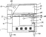
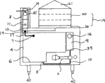
Fig. 1 is the schematic right-side view according to steamer embodiment of the present utility model;
Fig. 2 is the schematic elevational view of the steamer of Fig. 1;
Fig. 3 is the schematic left view of the steamer of Fig. 1;
Fig. 4 is the perspective schematic view of the steamer of Fig. 1, the passage and the layout of the heat exchange between the flue that have wherein shown between preheating water source and the flue and be used to produce steam;
Fig. 5 be by as shown in the schematic elevational view of steamer and the left view as described in the form of performance of steamer of the temperature survey key diagram 1 that carries out of a plurality of somes place of steamer; With
Fig. 6 is the picture specification of performance of the steamer of Fig. 5.
The specific embodiment
With reference to Fig. 1 in the accompanying drawing-6, show embodiment according to steamer 1 of the present utility model, described steamer has at the gas burner 2 at 37 places, bottom of steamer 1 with above burner 2 and closely near the vaporium 4 of burner 2.Steamer 1 is positioned on four bases 40.Described steamer comprises that the temperature of the temperature of controlling steamer 1 disconnects (cut-off) sensor.
Steamer 1 comprises preheating water source (cistern) 8, and the form at described preheating water source is water tank 8T, and the water inlet 5 of vaporium 4 is connected to described preheating water source (cistern) 8 via break tank (break tank) 9 and water pipe 10a and 10b.Preheating water tank 8T has top water inlet 12, and described top water inlet is connected to the main water supply that water under the room temperature that is used to allow 21.2 ℃ enters into water tank 8T.
Preheating water tank 8T is associated with flue 11 in first heat-exchange device.Water tank 8T be positioned at the rear side of steam chamber 4 flue 11 above the top 36 of described steam chamber top 15 around.By surrounding top 15, the water in water tank 8T is heated to about 48.1 ℃ by the heat energy that conducts from the waste gas that rises by flue 11.By this way, the water that the part of the heat of the waste gas in the flue 11 is preheated among the water tank 8T reclaims, otherwise, will be wasted.Preheating water will need less energy being heated to flash-point, and described layout has improved the energy efficiency of steamer 1.
In order to make water and the maximization of the heat exchange between the waste gas in the flue 11 among the preheating water tank 8T, water inlet 12 leads to 22 water passages 30 among the water tank 8T, and described water passage is arranged in the inside of cross over flue 11 and the triplex row of extending in whole described flue inside.Water passage 30 is used to improve the water of conduction by increase and the contact-making surface area between the gas increases heat exchange.
Ball-cock assembly 34 is used among the preheating water tank 8T with the horizontal plane among the control water tank 8T.Ball float 31 is connected to the valve (not shown) that is installed in inlet 12 places by the method for bar 33.Reduce ball float 31 valve will be opened, 12 enter water tank 8T by entering the mouth to allow water.Ball float 31 will rise with shut off valve gradually with the horizontal plane among the water tank 8T, enter water tank 8T thereby reduce and finally stop water.
Preheating water tank 8T has the bottom water outlet 13 that is used to distribute preheating water, and described bottom water outlet is connected to the water inlet 38 of break tank 9 by pipe 10b.Preheating water among the water tank 8T by enter the mouth 38 and water pipe 10b enter break tank 9.Break tank 9 has water out 39, and described water out is connected to the inlet 5 of vaporium 4 by pipe 10a.
Steam produces in the time of about 100.1 ℃, and temporarily is stored in the vaporium 4.Allow steam by steam (vapor) outlet 7 dischargings.Steam pipe 17 is connected to outlet 7 to deliver a vapor in the flue 11.Position below the top 36 of vaporium 4, steam pipe 17 is associated with flue 11 in second heat-exchange device by the inside of the bottom 14 of flue 11 by horizontal-extending.
Preheating water tank 8T and steam pipe 17 are relatively more crucial with respect to the position of flue 11.Water tank 8T is placed on the top of steam pipe 17 along flue 11, that is, and and in the downstream of exhaust gas direction.The temperature of bottom 14 (upstream) is higher than the temperature in top 15 (downstream).Need higher temperature to form superheated steam, and therefore steam pipe 17 is placed in the bottom 14.
After the inside that moves through flue 11, steam pipe 17 will be directed to the circulation steamer outlet 24 in the top 36 of vaporium 4 from the steam of flue 11.Steamer outlet 24 is formed with and is used for keeping in the above folding the short flange of food retainer such as one of the bamboo retainer with porous bottom 22, thereby is formed for the vaporium 19 of steamed wheaten foods thing together.
Temperature at the steam at steam (vapor) outlet 24 places is approximately 101.2 ℃.Uppermost food retainer 20 tegmentums 21 hide.Steam be maintained in the vaporium 19 with culinary art or again heat packs be contained in food in the retainer 20.Superheated steam provides than the better steam effect of normal temperature, and described normal temperature is usually just in time under the temperature below 100 ℃.
As shown in Figure 5 and Figure 6, above-mentioned layout allows flue temperature to drop at about 129.1 ℃ (T6) of top flue outlet and drop to about 222.1 ℃ (T5) at 14 places in the bottom from average about 250 ℃ along flue length.
In addition, above-mentioned layout produces better energy efficient.The water that enters preheating water tank 8T is approximately 21.2 ℃, and is preheating to 48.1 ℃ by the heat of retrieving the waste gas in flue 11.Steam is produced more quickly and is needed less heat from burner 2.In addition, the vapor (steam) temperature before entering steam pipe 17 is approximately 100.1 ℃ (T3).Steam in steam pipe 17 is heated to form the superheated steam of about 106.8 ℃ (T4) from the heat of waste gas by retrieving.Steam at steam (vapor) outlet 24 places remains on about 101.2 ℃ (T7).The mean value of the energy efficiency of steamer 1 is approximately 80% in whole 150 minute running time, and this is than the energy efficiency high about 10% of traditional steamer.
When above-mentioned measurement occurs in ambient temperature and is approximately 20.1 ℃.About 0.71lit/min of steam rate and CO/CO
2Than being approximately 0.0052.
Being understood that conspicuous improvement and variation, manufacturing and use should be thought concerning the technical staff in steamer field does not exceed protection domain of the present utility model.For example, vaporium is arranged on the top of steamer.In optional embodiment, vaporium can be placed in the steamer 1.
Claims (10)
Applications Claiming Priority (2)
| Application Number | Priority Date | Filing Date | Title |
|---|---|---|---|
| HK09104171A HK1136457A2 (en) | 2009-05-06 | 2009-05-06 | Food steamer |
| HK09104171.4 | 2009-05-06 |
Publications (1)
| Publication Number | Publication Date |
|---|---|
| CN201743473U true CN201743473U (en) | 2011-02-16 |
Family
ID=42272365
Family Applications (1)
| Application Number | Title | Priority Date | Filing Date |
|---|---|---|---|
| CN2010201131318U Expired - Lifetime CN201743473U (en) | 2009-05-06 | 2010-02-03 | Food steamer |
Country Status (2)
| Country | Link |
|---|---|
| CN (1) | CN201743473U (en) |
| HK (1) | HK1136457A2 (en) |
Cited By (2)
| Publication number | Priority date | Publication date | Assignee | Title |
|---|---|---|---|---|
| CN103767875A (en) * | 2014-01-20 | 2014-05-07 | 延边檀君生物科技有限公司 | Ginseng steamer capable of preventing loss of saponin |
| CN121512351A (en) * | 2026-01-15 | 2026-02-13 | 美的集团股份有限公司 | Cooking equipment and cooking systems |
-
2009
- 2009-05-06 HK HK09104171A patent/HK1136457A2/en not_active IP Right Cessation
-
2010
- 2010-02-03 CN CN2010201131318U patent/CN201743473U/en not_active Expired - Lifetime
Cited By (2)
| Publication number | Priority date | Publication date | Assignee | Title |
|---|---|---|---|---|
| CN103767875A (en) * | 2014-01-20 | 2014-05-07 | 延边檀君生物科技有限公司 | Ginseng steamer capable of preventing loss of saponin |
| CN121512351A (en) * | 2026-01-15 | 2026-02-13 | 美的集团股份有限公司 | Cooking equipment and cooking systems |
Also Published As
| Publication number | Publication date |
|---|---|
| HK1136457A2 (en) | 2010-06-25 |
Similar Documents
| Publication | Publication Date | Title |
|---|---|---|
| CN201263616Y (en) | Gas steam generator | |
| KR101156188B1 (en) | Pellet stove all warm | |
| CN201743473U (en) | Food steamer | |
| JP2014126356A (en) | Heater with firewood as its fuel | |
| RU2470230C1 (en) | Steam generating method and device for its implementation | |
| CN102559432B (en) | Energy-saving steaming and boiling system | |
| RU111261U1 (en) | DEVICE FOR FEEDING VAPORIZING LIQUID | |
| CN206787040U (en) | A kind of normal pressure fuel-firing gas-firing numerical control boiler | |
| CN201028481Y (en) | Gas steam engine | |
| KR101173390B1 (en) | Steam Ovens | |
| CN204201856U (en) | A kind of high efficiency burnt gas steam generator | |
| CN100512727C (en) | Gas steam engine | |
| KR101066786B1 (en) | Steam cooker | |
| CN205433329U (en) | Cabinet is evaporated in energy -concerving and environment -protective type gas | |
| CN205655328U (en) | Energy conservation furnace | |
| CN203207789U (en) | Gas steam cabinet | |
| CN202492512U (en) | Energy-saving steaming and boiling system | |
| CN207648757U (en) | Gas steam generator | |
| RU2472071C1 (en) | Oven | |
| CN201535498U (en) | High-temperature fuel gas steam engine | |
| CN205535718U (en) | Steam generator and evaporate cabinet | |
| KR100699446B1 (en) | Multi-purpose waste heat recovery machine | |
| CN201045492Y (en) | a steam generator | |
| CN213097477U (en) | Energy-conserving efficient three-door seafood evaporates cabinet | |
| CN201155800Y (en) | Multi-stage energy-saving steam stove |
Legal Events
| Date | Code | Title | Description |
|---|---|---|---|
| C14 | Grant of patent or utility model | ||
| GR01 | Patent grant | ||
| CX01 | Expiry of patent term |
Granted publication date: 20110216 |
|
| CX01 | Expiry of patent term |