CN201843143U - Deep water single-wall steel suspension box cofferdam - Google Patents
Deep water single-wall steel suspension box cofferdam Download PDFInfo
- Publication number
- CN201843143U CN201843143U CN2010205296574U CN201020529657U CN201843143U CN 201843143 U CN201843143 U CN 201843143U CN 2010205296574 U CN2010205296574 U CN 2010205296574U CN 201020529657 U CN201020529657 U CN 201020529657U CN 201843143 U CN201843143 U CN 201843143U
- Authority
- CN
- China
- Prior art keywords
- welded
- steel
- back cord
- side plate
- deep water
- Prior art date
- Legal status (The legal status is an assumption and is not a legal conclusion. Google has not performed a legal analysis and makes no representation as to the accuracy of the status listed.)
- Expired - Lifetime
Links
- 229910000831 Steel Inorganic materials 0.000 title claims abstract description 97
- 239000010959 steel Substances 0.000 title claims abstract description 97
- XLYOFNOQVPJJNP-UHFFFAOYSA-N water Substances O XLYOFNOQVPJJNP-UHFFFAOYSA-N 0.000 title claims abstract description 21
- 239000000725 suspension Substances 0.000 title claims description 14
- 238000003466 welding Methods 0.000 claims abstract description 5
- XEEYBQQBJWHFJM-UHFFFAOYSA-N Iron Chemical compound [Fe] XEEYBQQBJWHFJM-UHFFFAOYSA-N 0.000 claims description 22
- 229910052742 iron Inorganic materials 0.000 claims description 11
- 239000003351 stiffener Substances 0.000 claims description 5
- 230000008878 coupling Effects 0.000 claims description 3
- 238000010168 coupling process Methods 0.000 claims description 3
- 238000005859 coupling reaction Methods 0.000 claims description 3
- 210000003746 feather Anatomy 0.000 claims description 3
- 239000002352 surface water Substances 0.000 claims description 3
- 238000010276 construction Methods 0.000 abstract description 18
- 238000000034 method Methods 0.000 abstract description 5
- UZVHFVZFNXBMQJ-UHFFFAOYSA-N butalbital Chemical compound CC(C)CC1(CC=C)C(=O)NC(=O)NC1=O UZVHFVZFNXBMQJ-UHFFFAOYSA-N 0.000 description 4
- 230000008595 infiltration Effects 0.000 description 2
- 238000001764 infiltration Methods 0.000 description 2
- 230000009286 beneficial effect Effects 0.000 description 1
- 238000007796 conventional method Methods 0.000 description 1
- 238000010586 diagram Methods 0.000 description 1
- 238000005516 engineering process Methods 0.000 description 1
- 238000005096 rolling process Methods 0.000 description 1
- 230000007306 turnover Effects 0.000 description 1
Images




Landscapes
- Revetment (AREA)
Abstract
The utility model relates to a deep water single wall steel hanging box cofferdam, the steel hanging box includes enclosure system, interior support system and holds the system of hanging, hold the system of hanging and comprise hoist and mount bracket, entablature, bottom end rail and jib, the welding of hoist and mount bracket is in the inboard of curb plate, and the entablature is located the top surface of vertical steel casing, passes through the jib with the hoist and mount bracket and is connected, and the bottom end rail welding is in pile bolck position department, and is parallel with the entablature. The utility model provides a traditional cofferdam back cover concrete quality be difficult to guarantee, the easy technical problem who seeps water and leak of appearing. The method can be widely applied to construction of pile caps and piers in deep water areas.
Description
Technical field
The utility model relates to a kind of deep water single-wall steel suspended box cofferdam, particularly a kind of single-wall steel suspended box cofferdam and job practices thereof that is adapted at the profundal zone use.
Background technology
In silt matter argillic horizon deep water foundation cofferdam construction, conventional method is to adopt Larsen steel sheet-pile cofferdam or steel suspended box cofferdam construction, steel sheet-pile cofferdam has long construction period, progress is slow, bottom concrete is thick, the bottom concrete construction quality is difficult to guarantee that infiltration and drainage appear in steel sheet pile construction easily, influence shortcomings such as follow-up engineering construction.Common steel suspended box cofferdam exists a heavy load of cofferdam, profundal zone sinking process quite big, unfavorable construction and control often need to adjust with jack, difficulty of construction is big, engineering progress is slow, general nothing supports at the bottom of the steel suspension box simultaneously, owing between stake and casing mud is arranged, frictional force reduces behind the steel box sinking correct position, and the steel box may continue to sink and need shortcomings such as crane works on.
The utility model content
The purpose of this utility model provides a kind of deep water single-wall steel suspended box cofferdam, and solve in the conventional steel box sinking process needs to adopt jack adjustment, and difficulty of construction is big, the technical problem that engineering progress is slow; And solve the problem that still needs crane behind the steel box sinking correct position.
For achieving the above object, the utility model adopts following technical scheme:
A kind of deep water single-wall steel suspended box cofferdam, comprise the system of going along with sb. to guard him, inner supporting body system and hold the system of hanging, fender body is that system is gone along with sb. to guard him in the side and the rectangle box that system surrounds is gone along with sb. to guard him in the bottom, the side is gone along with sb. to guard him system and is comprised side plate, horizontal back cord, vertical back cord and angle steel, the system base plate is gone along with sb. to guard him in the bottom, vertical back cord and horizontal back cord, inner supporting body system is supported on the side plate inboard, holding the system of hanging is connected the side fender body and fastens, the described system of hanging of holding is by the lifting bracket, top rail, lower transverse beam and suspension rod are formed, the lifting bracket is welded on the inboard of side plate, top rail is positioned at the end face of vertical steel casing, be connected by suspension rod with the lifting bracket, lower transverse beam is welded on position, stake top, and is parallel with top rail.
The lateral surface of described side plate is welded with crisscross horizontal back cord and vertical back cord, and the side plate feather edge is welded with angle steel, and the leg of angle back of the body is close to the side plate external surface, and the following 30cm of side plate lateral surface water surface position is welded with outlet valve.
The bottom surface of described base plate is welded with crisscross vertical back cord and horizontal back cord, vertical back cord is positioned at horizontal back cord bottom surface, bracket is supported at the bottom of being welded with case in horizontal back cord bottom surface, have hole between the horizontal back cord of described two row at interval with steel casing coupling, vertical back cord is met hole and is disconnected, and the hole ambient level is to being welded with short stiffener.
Described inner supporting body system by support bracket, enclose purlin, horizontal steel tube and shaped steel supports and forms, enclose purlin and be welded on the inboard of side plate, shaped steel support be welded at interval two than appearance to the side plate inboard, in its bottom surface crisscross horizontal steel tube is arranged, the end of horizontal steel tube is welded on the side plate inner surface, and described support bracket is welded on the horizontal steel tube bottom surface and is welded to connect with the side plate inner surface.
Described lower transverse beam end face is welded with lower transverse beam and connects bracket.
Described lower transverse beam is duplexing font steel or the relative box beam that is spliced into of double flute steel tank mouth with top rail.
Described lifting bracket connects welding for two i iron, and its upper surface i iron web correspondence position is welded with steel plate.
Described suspension rod is an indented bars, and its two ends are fixed respectively at top rail and lifting bracket by nut, and between the contact surface backing plate are arranged.
Compared with prior art the utlity model has following characteristics and beneficial effect:
At first, the utility model adds one lower transverse beam and prevents between stake and casing mud is arranged by having on stake top, and frictional force reduces, and causes the steel box to sink; Make work progress easier without the jack adjustment, reduce difficulty of construction, the reduction of erection time.
Secondly, the utility model supports bracket and is used to support the steel box at the bottom of the bottom surface of base plate system is welded with case, guarantees in the steel box sinking process that the steel box supports, and the steel box can remove crane after sinking simultaneously, the turnover of increase equipment.
It is long that the utility model has overcome the conventional steel plates pile driving construction cycle, progress is slow, bottom concrete is thick, the bottom concrete construction quality is difficult to guarantee, infiltration and drainage appear in construction easily, influence shortcoming such as follow-up engineering construction and common steel suspended box cofferdam exist cofferdam, profundal zone sinking process to play heavy load quite big, unfavorable construction and control often need to adjust with jack, difficulty of construction is big, engineering progress is slow, general nothing supports at the bottom of the steel suspension box simultaneously, owing between stake and casing mud is arranged, frictional force reduces behind the steel box sinking correct position, and the steel box may continue to sink and need shortcomings such as crane works on, solve the steel box and sunk to need not the jack adjustment, sunk down into the technical problem that can remove the simple and effective realization cofferdam of crane behind the cushion cap position.
The utility model can be widely used in the construction of profundal zone pile cap and bridge pier.
Description of drawings
The utility model is described in more detail below in conjunction with accompanying drawing.
Fig. 1 is the positive elevational schematic view of the utility model deep water single-arm steel hanging box.
Fig. 2 is the utility model deep water single-arm steel hanging box side elevation schematic diagram.
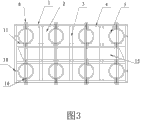
Fig. 3 is the utility model deep water single-arm steel hanging box floor map.
Fig. 4 is a base plate system detail drawing.
Fig. 5 is a side plate system detail drawing.
Reference numeral: 1-goes along with sb. to guard him system in the side, 1.1-side plate, 1.2-horizontal back cord, 1.3-vertical back cord, 1.4-angle steel, 2-goes along with sb. to guard him system in the bottom, 2.1-base plate, 2.2-vertical back cord, 2.3-horizontal back cord, 2.4-hole, 2.5-short stiffener, the 3-horizontal steel tube, 4-encloses purlin, 5-steel casing, the 6-top rail, 7-supports bracket, the 8-suspension rod, the 9-lower transverse beam, 10-lifts bracket, 11-shaped steel supports, the 12-outlet valve, the 13-lower transverse beam connects bracket, support bracket at the bottom of the 14-case, 15-plans to build pile foundation.
The specific embodiment
Embodiment is referring to Fig. 1~shown in Figure 5, a kind of deep water single-wall steel suspended box cofferdam, go along with sb. to guard him around deepwater regions is planned to build the steel casing 5 of pile foundation 15, comprise the system of going along with sb. to guard him, inner supporting body system and hold the system of hanging, fender body is that system 1 is gone along with sb. to guard him in the side and the rectangle box that system 2 surrounds is gone along with sb. to guard him in the bottom, the side is gone along with sb. to guard him system and is comprised side plate 1.1, horizontal back cord 1.2, vertical back cord 1.3 and angle steel 1.4, system base plate 2.1 is gone along with sb. to guard him in the bottom, vertical back cord 2.2 and horizontal back cord 2.3, inner supporting body system is supported on the side plate inboard, holding the system of hanging is connected the side fender body and fastens, the described system of hanging of holding is by lifting bracket 10, top rail 6, lower transverse beam 9 and suspension rod 8 are formed, lifting bracket 10 is welded on the inboard of side plate, top rail 6 is positioned at the end face of vertical steel casing, be connected by suspension rod 8 with lifting bracket 10, lower transverse beam 9 is welded on position, stake top, and is parallel with top rail 6.
The lateral surface of described side plate 1.1 is welded with crisscross horizontal back cord 1.2 and vertical back cord 1.3, and the side plate feather edge is welded with angle steel 1.4, and the leg of angle back of the body is close to the side plate external surface, and the following 30cm of side plate lateral surface water surface position is welded with outlet valve 12.
The bottom surface of described base plate 2.1 is welded with crisscross vertical back cord 2.2 and horizontal back cord 2.3, vertical back cord 2.2 is positioned at horizontal back cord 2.3 bottom surfaces, bracket 14 is supported at the bottom of being welded with case in horizontal back cord 2.3 bottom surfaces, separate the hole 2.4 that has with steel casing coupling between the horizontal back cord of described two row, vertical back cord 2.2 is met hole 2.4 and is disconnected, and the hole ambient level is to being welded with short stiffener 2.5.
Described inner supporting body system by support bracket 7, enclose purlin 4, horizontal steel tube 3 and shaped steel supports 11 and forms, enclose purlin 4 and be welded on the inboard of side plate, shaped steel support 11 be welded at interval two than appearance to the side plate inboard, in its bottom surface crisscross horizontal steel tube 3 is arranged, the end of horizontal steel tube 3 is welded on the side plate inner surface, and described support bracket 7 is welded on horizontal steel tube 3 bottom surfaces and is welded to connect with the side plate inner surface.
Described lower transverse beam 9 end faces are welded with lower transverse beam and connect bracket 13.
Described lower transverse beam 9 is duplexing font steel or the relative box beam that is spliced into of double flute steel tank mouth with top rail 6.
Described lifting bracket 10 connects welding for two i iron, and its upper surface i iron web correspondence position is welded with steel plate.
Described suspension rod 8 is an indented bars, and its two ends are fixing respectively at top rail 6 and lifting bracket 10 by nut, and backing plate is arranged between the contact surface.
Base plate 2.1 adopts the 6mm steel plate, and vertical back cord 2.2 is that worker 25b and horizontal back cord 2.3 are that [8, short stiffener 2.5 is the 80*6mm steel plate; Side plate 1.1 adopts the 6mm steel plates, horizontal back cord 1.2 be [8 and vertical back cord 1.3 for [14, angle steel employing ∠ 75 * 75 * 8 angles with equal legs; Support bracket 14 is processed by the 10mm steel plate at the bottom of supporting bracket 7, crossbeam connection bracket 13 and case, encloses purlin 4 and is Two bors d's oeuveres worker 25b i iron, and it is Two bors d's oeuveres worker 25b i iron that horizontal steel tube 3 adopts φ 325 * 8mm steel pipes and shaped steel to support 11; Lifting bracket 10 adopts worker's 25b i iron and 10mm steel plate to be welded, and top rail 6 adopts Two bors d's oeuveres worker 45b i iron, and lower transverse beam 9 adopts Two bors d's oeuveres worker 25b i iron, and suspension rod 8 is No. 25 a finish rolling deformed bar.
Base plate adds every 1m with side plate, side plate and side plate junction and welds the thick steel plate of putting more energy into of 6mm, guarantees steel box integral rigidity.
Claims (8)
1. deep water single-wall steel suspended box cofferdam, comprise the system of going along with sb. to guard him, inner supporting body system and hold the system of hanging, fender body is that system (1) is gone along with sb. to guard him in the side and the rectangle box that system (2) surrounds is gone along with sb. to guard him in the bottom, the side is gone along with sb. to guard him system and is comprised side plate (1.1), horizontal back cord (1.2), vertical back cord (1.3) and angle steel (1.4), system base plate (2.1) is gone along with sb. to guard him in the bottom, vertical back cord (2.2) and horizontal back cord (2.3), inner supporting body system is supported on the side plate inboard, holding the system of hanging is connected the side fender body and fastens, it is characterized in that: the described system of hanging of holding is by lifting bracket (10), top rail (6), lower transverse beam (9) and suspension rod (8) are formed, lifting bracket (10) is welded on the inboard of side plate, top rail (6) is positioned at the end face of vertical steel casing, be connected by suspension rod (8) with lifting bracket (10), lower transverse beam (9) is welded on position, stake top, and is parallel with top rail (6).
2. deep water single-wall steel suspended box cofferdam according to claim 1, it is characterized in that: the lateral surface of described side plate (1.1) is welded with crisscross horizontal back cord (1.2) and vertical back cord (1.3), the side plate feather edge is welded with angle steel (1.4), the leg of angle back of the body is close to the side plate external surface, and the following 30cm of side plate lateral surface water surface position is welded with outlet valve (12).
3. deep water single-wall steel suspended box cofferdam according to claim 1, it is characterized in that: the bottom surface of described base plate (2.1) is welded with crisscross vertical back cord (2.2) and horizontal back cord (2.3), vertical back cord (2.2) is positioned at horizontal back cord (2.3) bottom surface, bracket (14) is supported at the bottom of being welded with case in horizontal back cord (2.3) bottom surface, have hole (2.4) between the horizontal back cord of described two row at interval with steel casing coupling, vertical back cord (2.2) is met hole (2.4) and is disconnected, and the hole ambient level is to being welded with short stiffener (2.5).
4. deep water single-wall steel suspended box cofferdam according to claim 1, it is characterized in that: described inner supporting body system by support bracket (7), enclose purlin (4), horizontal steel tube (3) and shaped steel supports (11) and forms, enclose purlin (4) and be welded on the inboard of side plate, shaped steel support (11) be welded at interval two than appearance to the side plate inboard, crisscross horizontal steel tube (3) is arranged in its bottom surface, the end of horizontal steel tube (3) is welded on the side plate inner surface, and described support bracket (7) is welded on horizontal steel tube (3) bottom surface and is welded to connect with the side plate inner surface.
5. deep water single-wall steel suspended box cofferdam according to claim 1 is characterized in that: described lower transverse beam (9) end face is welded with lower transverse beam and connects bracket (13).
6. deep water single-wall steel suspended box cofferdam according to claim 1 is characterized in that: described lower transverse beam (9) is duplexing font steel or the relative box beam that is spliced into of double flute steel tank mouth with top rail (6).
7. deep water single-wall steel suspended box cofferdam according to claim 1 is characterized in that: described lifting bracket (10) connects welding for two i iron, and its upper surface i iron web correspondence position is welded with steel plate.
8. deep water single-wall steel suspended box cofferdam according to claim 1 is characterized in that: described suspension rod (8) is an indented bars, and its two ends are fixing with top rail (6) and lifting bracket (10) respectively by nut, and backing plate is arranged between the contact surface.
Priority Applications (1)
| Application Number | Priority Date | Filing Date | Title |
|---|---|---|---|
| CN2010205296574U CN201843143U (en) | 2010-09-15 | 2010-09-15 | Deep water single-wall steel suspension box cofferdam |
Applications Claiming Priority (1)
| Application Number | Priority Date | Filing Date | Title |
|---|---|---|---|
| CN2010205296574U CN201843143U (en) | 2010-09-15 | 2010-09-15 | Deep water single-wall steel suspension box cofferdam |
Publications (1)
| Publication Number | Publication Date |
|---|---|
| CN201843143U true CN201843143U (en) | 2011-05-25 |
Family
ID=44038037
Family Applications (1)
| Application Number | Title | Priority Date | Filing Date |
|---|---|---|---|
| CN2010205296574U Expired - Lifetime CN201843143U (en) | 2010-09-15 | 2010-09-15 | Deep water single-wall steel suspension box cofferdam |
Country Status (1)
| Country | Link |
|---|---|
| CN (1) | CN201843143U (en) |
Cited By (7)
| Publication number | Priority date | Publication date | Assignee | Title |
|---|---|---|---|---|
| CN101936009A (en) * | 2010-09-15 | 2011-01-05 | 中建二局土木工程有限公司 | Deep-water single-wall steel hanging box cofferdam and construction method thereof |
| CN103195071A (en) * | 2013-03-25 | 2013-07-10 | 浙江省隧道工程公司 | Riding-pipe steel plate earth core filling coefferdam structure and construction process thereof |
| CN103821157A (en) * | 2014-02-27 | 2014-05-28 | 山东省路桥集团有限公司 | Wallboard lattice type steel cover box and method for constructing underwater bearing platform steel cover box |
| CN103924608A (en) * | 2014-04-18 | 2014-07-16 | 中交第一公路工程局有限公司 | Detachable steel cover box device with bottom |
| CN104631338A (en) * | 2015-02-16 | 2015-05-20 | 中交第二航务工程局有限公司 | Steel boxed cofferdam and positioning construction method |
| CN110777825A (en) * | 2019-10-18 | 2020-02-11 | 安徽省路港工程有限责任公司 | Concrete back cover of deep water steel cofferdam and construction method thereof |
| CN114717945A (en) * | 2022-03-09 | 2022-07-08 | 中国建筑土木建设有限公司 | Construction method and structure for supporting bottom of deep water tidal section high pile cap |
-
2010
- 2010-09-15 CN CN2010205296574U patent/CN201843143U/en not_active Expired - Lifetime
Cited By (11)
| Publication number | Priority date | Publication date | Assignee | Title |
|---|---|---|---|---|
| CN101936009A (en) * | 2010-09-15 | 2011-01-05 | 中建二局土木工程有限公司 | Deep-water single-wall steel hanging box cofferdam and construction method thereof |
| CN101936009B (en) * | 2010-09-15 | 2012-03-07 | 中建二局土木工程有限公司 | Deep-water single-wall steel hanging box cofferdam and construction method thereof |
| CN103195071A (en) * | 2013-03-25 | 2013-07-10 | 浙江省隧道工程公司 | Riding-pipe steel plate earth core filling coefferdam structure and construction process thereof |
| CN103821157A (en) * | 2014-02-27 | 2014-05-28 | 山东省路桥集团有限公司 | Wallboard lattice type steel cover box and method for constructing underwater bearing platform steel cover box |
| CN103821157B (en) * | 2014-02-27 | 2015-09-16 | 山东省路桥集团有限公司 | Wallboard lattice steel jacket box and under water held platform set box construction method |
| CN103924608A (en) * | 2014-04-18 | 2014-07-16 | 中交第一公路工程局有限公司 | Detachable steel cover box device with bottom |
| CN103924608B (en) * | 2014-04-18 | 2016-05-04 | 中交第一公路工程局有限公司 | A kind of detachable end steel jacket box device that has |
| CN104631338A (en) * | 2015-02-16 | 2015-05-20 | 中交第二航务工程局有限公司 | Steel boxed cofferdam and positioning construction method |
| CN110777825A (en) * | 2019-10-18 | 2020-02-11 | 安徽省路港工程有限责任公司 | Concrete back cover of deep water steel cofferdam and construction method thereof |
| CN110777825B (en) * | 2019-10-18 | 2021-03-30 | 安徽省路港工程有限责任公司 | Concrete back cover of deep water steel cofferdam and its construction method |
| CN114717945A (en) * | 2022-03-09 | 2022-07-08 | 中国建筑土木建设有限公司 | Construction method and structure for supporting bottom of deep water tidal section high pile cap |
Similar Documents
| Publication | Publication Date | Title |
|---|---|---|
| CN201843143U (en) | Deep water single-wall steel suspension box cofferdam | |
| CN101936009B (en) | Deep-water single-wall steel hanging box cofferdam and construction method thereof | |
| CN101775809B (en) | Construction method of marine self-floating type steel soleplate single-wall suspension box cofferdam and single-wall suspension box cofferdam | |
| CN104389313B (en) | The positioning and plumbing device of Two bors d's oeuveres type i iron lattice column and positioning and plumbing method thereof | |
| CN103741657B (en) | The construction method of large-sized multifunction waterborne traffic accident | |
| CN203145038U (en) | lattice column type tower crane foundation | |
| CN201850498U (en) | Steel trestle in water | |
| CN102134854B (en) | Slipway underwater pile foundation and construction method thereof | |
| CN201891123U (en) | Single-wall steel hanging box with concrete bottom plate | |
| CN208309593U (en) | A kind of steel pipe structure with oblique member | |
| CN204000905U (en) | A kind of Double-Wall Steel Boxed Cofferdam with binder deep water bearing platform construction | |
| CN204662444U (en) | Large diameter steel pipe sunk pile fixed guide | |
| CN102587377B (en) | Drop hammer type pile sinking device and pile sinking method thereof | |
| CN204455847U (en) | The marine positioning guiding device of the prefabricated pier of large-tonnage | |
| CN206635801U (en) | A kind of deep water waters bridge construction tower-crane foundation structure | |
| CN203782670U (en) | Floating box platform for over-water construction | |
| CN112267486B (en) | Steel pipe concrete anti-seismic bridge pile foundation and pile foundation construction method | |
| CN204151665U (en) | A kind of cable-stayed type opens trestle | |
| CN209099351U (en) | Back taper steel jacket box in water in the prefabricated constructing tie beam of pier foundation | |
| CN205742089U (en) | A kind of anchor ear support means | |
| CN202492846U (en) | Drop hammer pile-sinking device | |
| CN206438385U (en) | A kind of adjustable bridge floor cushioning and supporting device | |
| CN216787177U (en) | Single-wall steel hanging box | |
| CN205742246U (en) | Pillar tower crane base is used in a kind of river | |
| CN204551494U (en) | Construction equipment is transferred in a kind of steel sheet-pile cofferdam inner support superposition |
Legal Events
| Date | Code | Title | Description |
|---|---|---|---|
| C14 | Grant of patent or utility model | ||
| GR01 | Patent grant | ||
| AV01 | Patent right actively abandoned |
Granted publication date: 20110525 Effective date of abandoning: 20120307 |