CN202492846U - Drop hammer pile-sinking device - Google Patents
Drop hammer pile-sinking device Download PDFInfo
- Publication number
- CN202492846U CN202492846U CN2012200546977U CN201220054697U CN202492846U CN 202492846 U CN202492846 U CN 202492846U CN 2012200546977 U CN2012200546977 U CN 2012200546977U CN 201220054697 U CN201220054697 U CN 201220054697U CN 202492846 U CN202492846 U CN 202492846U
- Authority
- CN
- China
- Prior art keywords
- pile
- piles
- engineering
- engineering piles
- leading truck
- Prior art date
- Legal status (The legal status is an assumption and is not a legal conclusion. Google has not performed a legal analysis and makes no representation as to the accuracy of the status listed.)
- Expired - Fee Related
Links
- 229910000831 Steel Inorganic materials 0.000 claims abstract description 20
- 239000010959 steel Substances 0.000 claims abstract description 20
- 230000008093 supporting effect Effects 0.000 claims abstract description 13
- XLYOFNOQVPJJNP-UHFFFAOYSA-N water Substances O XLYOFNOQVPJJNP-UHFFFAOYSA-N 0.000 claims abstract description 11
- 229910000746 Structural steel Inorganic materials 0.000 claims description 13
- 230000002093 peripheral effect Effects 0.000 claims description 3
- 238000010276 construction Methods 0.000 abstract description 13
- 238000004519 manufacturing process Methods 0.000 abstract 1
- 239000000725 suspension Substances 0.000 abstract 1
- 230000003321 amplification Effects 0.000 description 1
- 230000015572 biosynthetic process Effects 0.000 description 1
- 230000000694 effects Effects 0.000 description 1
- 238000005516 engineering process Methods 0.000 description 1
- 238000000034 method Methods 0.000 description 1
- 238000003199 nucleic acid amplification method Methods 0.000 description 1
- 238000007789 sealing Methods 0.000 description 1
- 230000009466 transformation Effects 0.000 description 1
- 239000003643 water by type Substances 0.000 description 1
Images


Landscapes
- Placing Or Removing Of Piles Or Sheet Piles, Or Accessories Thereof (AREA)
Abstract
The utility model discloses a drop hammer pile-sinking device. The drop hammer pile-sinking device comprises a drop hammer guide frame and a pile-sinking support frame, wherein the drop hammer guide frame comprises an upper suspension bracket, a vertical guide seat and a lower engineering pile supporting seat, the vertical guide seat is provided with a vertical guide rail, the head of a power hammer is supported on the vertical guide rail, the top ends of engineering piles are supported in the lower engineering pile supporting seat, and the top end of the drop hammer guide frame is suspended on a hook of a crane through a crane cable; the pile-sinking support frame comprises a plurality of steel pipe piles with bottoms hammered into a water bottom by phi 600-800 mm, the plurality of steel pipe piles are distributed on a water surface in a polygonal shape, at least one layer of polygonal profile steel frame positioned on the water surface is fixedly connected with the plurality of steel pipe piles, the polygonal and rectangular profile steel frame is provided with a plurality of guide frames of which the number is equal to that of the engineering piles, and the sunk engineering piles are positioned in the guide frames. The drop hammer pile-sinking device has simple structure of the drop hammer guide frame and the pile-sinking support frame, convenience for manufacture and construction and convenience for the positioning of the engineering piles and the continuous hammering of the power hammer.
Description
Technical field
The utility model relates to a kind of Construction of Engineering Pile facility of building high-pile beam formula harbour, and especially a kind of pile sinking device that is used for steel pipe pile or PHC stake (strong concrete pipe) belongs to the port works technical field.
Background technology
Along the river or seashore limit when building high-pile beam formula harbour with access bridge, need to arrive at the bottom of the river many engineering piles pile sinking or the seabed earlier, these engineering piles become the job platform and the access bridge bridge floor of harbour as the beam slab that shore supports firmly forms with concreting.At present, the piling construction of steel pipe pile or PHC stake generally adopts the pile driving barge construction on the domestic water, and construction cost is expensive.In addition, in the depth of water, the waters that can not satisfy pile driving barge construction, pile driving barge can't move under the situation such as stake position, and pile driving barge is constructed and can not be carried out.
Summary of the invention
The purpose of the utility model provides a kind of sash weight pile sinking device, and this pile sinking device utilizes the continuous hammering of power hammer that is installed in the sash weight leading truck to be positioned at the engineering piles top in the pile sinking bracing frame with loop wheel machine sash weight leading truck, thereby realizes the pile sinking of engineering piles.
The utility model is achieved through following technical scheme:
A kind of sash weight pile sinking device; Comprise sash weight leading truck and pile sinking bracing frame, said sash weight leading truck comprises the last hanger bracket that links into an integrated entity, upright guide holder and following engineering piles supporting seat, and said upright guide holder is provided with vertical guide; The hammer body of power hammer is fixed on upright guide holder upper end; The tup of power hammer is bearing on the vertical guide, and the engineering piles top is bearing in down in the engineering piles supporting seat, and sash weight leading truck top is suspended on the hook of loop wheel machine through hoist cable; The pile sinking bracing frame comprises that many root bottom parts throw water-bed steel pipe pile into, and many steel pipe piles become polygon to be distributed on the water surface, and the polygon structural steel frame that is positioned on the water surface of one deck is fixedly connected with many steel pipe piles at least; Polygon rectangle structural steel frame is provided with several leading trucks that equate with engineering piles quantity, and the engineering piles of pile sinking is positioned within the leading truck.
The purpose of the utility model can also further realize through following technical measures.
Aforesaid sash weight pile sinking device, wherein said leading truck is the polygonized structure that shaped steel is welded into, and is equipped with idler wheel mechanism on each limit of said polygonized structure.Said idler wheel mechanism comprises roller, roller mount and back shaft, and said roller is bearing on the roller mount through back shaft, and the engineering piles outer peripheral face is resisted against on the roller.
The sash weight leading truck and the pile sinking support frame structure of the utility model are simple, make and easy construction, are convenient to the continuous hammering of engineering piles location and power hammer.Adopt the utility model to carry out pile sinking, construction cost is merely 1/4~1/5 of pile driving barge piling construction, and construction cost is cheap, construction quality good.Construction quality and efficiency of construction have accurately been improved greatly in the engineering piles location.
Advantage of the utility model and characteristics will illustrate through the non-limitative illustration of following preferred embodiment and explain that these embodiment only provide with reference to accompanying drawing as an example.
Description of drawings
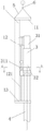
Fig. 1 is the sash weight leading truck side structure sketch map that the utility model is equipped with diesel hammer;
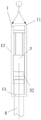
Fig. 2 is the sash weight leading truck structural representation that the utility model is equipped with hydraulic hammer;
Fig. 3 is the amplification A-A sectional view of Fig. 1;
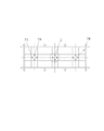
Fig. 4 is the pile sinking support frame structure sketch map of the utility model;
Fig. 5 is the vertical view of Fig. 4;
Fig. 6 is the I portion enlarged drawing of Fig. 5.
The specific embodiment
Below in conjunction with accompanying drawing and embodiment the utility model is described further.
Like Fig. 1~shown in Figure 3; Present embodiment comprises sash weight leading truck 1 and pile sinking bracing frame 2; Sash weight leading truck 1 comprises the last hanger bracket 11 that links into an integrated entity, upright guide holder 12 and following engineering piles supporting seat 13, and upright guide holder 12 is provided with vertical guide 121, and the hammer body 31 of power hammer 3 is fixed on upright guide holder 12 upper ends; The tup 32 of power hammer 3 is bearing on the vertical guide 121; Have the circular hole that can hold engineering piles 4 tops in the following engineering piles supporting seat 13, engineering piles 4 tops are bearing in down in the engineering piles supporting seat 13, and sash weight leading truck 1 top is suspended on the hook 6 of loop wheel machine through hoist cable 5.Fig. 1, Fig. 3 are side structure sketch map and the sectional views that the utility model is equipped with the sash weight leading truck 1 of diesel hammer; Go up hanger bracket 11, upright guide holder 12 and following engineering piles supporting seat 13 among Fig. 1 and be fixedly connected into the C font, the track base 311 of tup 31 downsides is buckled on the T-shaped vertical guide 121.Fig. 2 is sash weight leading truck 1 structural representation that the utility model is equipped with hydraulic hammer; Go up the shaped as frame that hanger bracket 11 and following engineering piles supporting seat 13 are fixedly connected into sealing among Fig. 2; Upright guide holder 12 is positioned at the both sides of shaped as frame; Tup 32 two-side supportings of hydraulic hammer are on the vertical guide 121 of sash weight leading truck 1, and the circular hole that engineering piles supporting seat 13 is passed down on engineering piles 4 tops is resisted against on tup 32 downsides.
Like Fig. 4, shown in Figure 5, pile sinking bracing frame 2 comprises that many root bottom parts are thrown the bottom into and the one-tenth polygon is distributed in the Φ 600 ~ 800mm steel pipe pile 21 on the water surface, and one deck is positioned at polygon structural steel frame and many steel pipe pile 21 companies of weldering on the water surface at least.The number of plies of polygon structural steel frame is relevant with the joint number of engineering piles 4, is not more than a engineering piles 4 that 30 meters stake joint forms through 41 butt joints of 4 side arcs by 2 joint single-unit length and need builds two-layer polygon structural steel frame and come propping works stake 4.21 one-tenth distributed rectangular of the steel pipe pile of present embodiment, polygon structural steel frame are the rectangle structural steel frame; The rectangle structural steel frame comprises first floor rectangle structural steel frame 25, second layer rectangle structural steel frame 22,, be respectively equipped with several and the leading truck 23 that engineering piles 4 quantity equate on the two-layer rectangle structural steel frame, engineering piles 4 is positioned within the leading truck 23.The polygonized structure that leading truck 23 is welded into for shaped steel, present embodiment are rectangular configuration.As shown in Figure 6, be equipped with idler wheel mechanism 24 on leading truck 23 each limit of polygonized structure.Said idler wheel mechanism 24 comprises roller 241, roller mount 242 and back shaft 243, and roller 241 is bearing on the roller mount 242 through back shaft 243, and engineering piles 4 outer peripheral faces are resisted against on the roller 241.Play guide effect in 24 pairs of engineering piles of idler wheel mechanism, the 4 piling processes.
The utility model also can be used for oblique engineering piles 4 pile sinking; Taper pile is selected steel pipe pile for use, and setting up of pile sinking bracing frame 2 is identical with straight stake, and leading truck 23 will be made oblique according to the slope of taper pile; It is consistent with oblique leading truck to adjust the pile body slope in the time of following; 2 different lengths that hang bundle of adjustment loop wheel machine suspention sash weight leading truck 1 make that the axis slope of sash weight leading truck 1 is consistent with oblique engineering piles 4 axis, carry out pile sinking with regard to 3 pairs of oblique engineering piles 4 of usable power hammer.
Except that the foregoing description, the utility model can also have other embodiments, and all employings are equal to the technical scheme of replacement or equivalent transformation formation, all drop in the protection domain of the utility model requirement.
Claims (3)
1. sash weight pile sinking device; It is characterized in that: comprise sash weight leading truck and pile sinking bracing frame, said sash weight leading truck comprises the last hanger bracket that links into an integrated entity, upright guide holder and following engineering piles supporting seat, and said upright guide holder is provided with vertical guide; The hammer body of power hammer is fixed on upright guide holder upper end; The tup of power hammer is bearing on the vertical guide, and the engineering piles top is bearing in down in the engineering piles supporting seat, and sash weight leading truck top is suspended on the hook of loop wheel machine through hoist cable; The pile sinking bracing frame comprises that many root bottom parts throw water-bed steel pipe pile into, and many steel pipe piles become polygon to be distributed on the water surface, and the polygon structural steel frame that is positioned on the water surface of one deck is fixedly connected with many steel pipe piles at least; Polygon rectangle structural steel frame is provided with several leading trucks that equate with engineering piles quantity, and the engineering piles of pile sinking is positioned within the leading truck.
2. sash weight pile sinking device as claimed in claim 1 is characterized in that: said leading truck is the polygonized structure that shaped steel is welded into, and is equipped with idler wheel mechanism on each limit of said polygonized structure.
3. sash weight pile sinking device as claimed in claim 2, it is characterized in that: said idler wheel mechanism comprises roller, roller mount and back shaft, and said roller is bearing on the roller mount through back shaft, and the engineering piles outer peripheral face is resisted against on the roller.
Priority Applications (1)
| Application Number | Priority Date | Filing Date | Title |
|---|---|---|---|
| CN2012200546977U CN202492846U (en) | 2012-02-21 | 2012-02-21 | Drop hammer pile-sinking device |
Applications Claiming Priority (1)
| Application Number | Priority Date | Filing Date | Title |
|---|---|---|---|
| CN2012200546977U CN202492846U (en) | 2012-02-21 | 2012-02-21 | Drop hammer pile-sinking device |
Publications (1)
| Publication Number | Publication Date |
|---|---|
| CN202492846U true CN202492846U (en) | 2012-10-17 |
Family
ID=46999081
Family Applications (1)
| Application Number | Title | Priority Date | Filing Date |
|---|---|---|---|
| CN2012200546977U Expired - Fee Related CN202492846U (en) | 2012-02-21 | 2012-02-21 | Drop hammer pile-sinking device |
Country Status (1)
| Country | Link |
|---|---|
| CN (1) | CN202492846U (en) |
Cited By (2)
| Publication number | Priority date | Publication date | Assignee | Title |
|---|---|---|---|---|
| CN102587377A (en) * | 2012-02-21 | 2012-07-18 | 中交二航局第三工程有限公司 | Drop hammer type pile sinking device and pile sinking method thereof |
| CN106414854A (en) * | 2014-05-22 | 2017-02-15 | Ihc荷兰Ie有限公司 | Tubular foundation |
-
2012
- 2012-02-21 CN CN2012200546977U patent/CN202492846U/en not_active Expired - Fee Related
Cited By (5)
| Publication number | Priority date | Publication date | Assignee | Title |
|---|---|---|---|---|
| CN102587377A (en) * | 2012-02-21 | 2012-07-18 | 中交二航局第三工程有限公司 | Drop hammer type pile sinking device and pile sinking method thereof |
| CN102587377B (en) * | 2012-02-21 | 2014-10-29 | 中交二航局第三工程有限公司 | Drop hammer type pile sinking device and pile sinking method thereof |
| CN106414854A (en) * | 2014-05-22 | 2017-02-15 | Ihc荷兰Ie有限公司 | Tubular foundation |
| US10072390B2 (en) | 2014-05-22 | 2018-09-11 | Ihc Holland Ie B.V. | Tubular foundation element, assembly and method for installing tubular foundation elements in a ground formation |
| CN106414854B (en) * | 2014-05-22 | 2020-01-10 | Ihc荷兰Ie有限公司 | Tubular foundation |
Similar Documents
| Publication | Publication Date | Title |
|---|---|---|
| CN202358280U (en) | Special ship for transporting large-diameter steel pipe piles and assisting in pile hoisting construction | |
| CN101240550A (en) | Construction method for lattice type steel column tower crane pedestal | |
| CN207277337U (en) | Special guide frame for pile sinking construction of offshore wind power pile group foundation | |
| CN214459689U (en) | Cast-in-place box girder support of weak soil foundation | |
| CN201843143U (en) | Deep water single-wall steel suspension box cofferdam | |
| CN216689329U (en) | Drilling platform based on marine steel batter pile support pile basis | |
| CN106088120B (en) | A kind of cofferdam decentralization construction method | |
| CN115387207A (en) | Shallow covering layer steel-concrete composite pile pier structure and construction method | |
| CN102587377B (en) | Drop hammer type pile sinking device and pile sinking method thereof | |
| CN202492846U (en) | Drop hammer pile-sinking device | |
| CN203144907U (en) | Large-span dual-layer bailey truss structure | |
| CN203782670U (en) | Floating box platform for over-water construction | |
| CN201292535Y (en) | Abysmal sea naked rock pier protecting barrel, spud and underwater cofferdam integration platform | |
| CN209816899U (en) | Floating pile-stabilizing platform for construction of steel pipe piles of offshore jacket type fan foundation | |
| CN202543878U (en) | Pile foundation construction platform for near-shore seafloor with agglomerate geological structure | |
| CN202131602U (en) | Steel sheet pile cofferdam structure | |
| CN201158825Y (en) | Lattice type steel column tower crane foundation seat | |
| CN212867456U (en) | Novel drilling platform hoist and mount formula jacket | |
| CN212534180U (en) | Foundation device of deep riverbed mast type wharf crane | |
| CN204875664U (en) | A retaining wall structure for interim pier in bay | |
| CN103352598A (en) | Positioning tower used for mounting multilayer cubic blocks in deep water | |
| CN202208929U (en) | Support reinforcing device for underground pipeline occupying support structure | |
| CN210368964U (en) | Precast pile positioning aid | |
| CN201746815U (en) | Pier structure adopting three-legged stand | |
| CN207176719U (en) | Steel lattice column combined type tower-crane foundation structure in a kind of foundation ditch |
Legal Events
| Date | Code | Title | Description |
|---|---|---|---|
| C14 | Grant of patent or utility model | ||
| GR01 | Patent grant | ||
| CF01 | Termination of patent right due to non-payment of annual fee | ||
| CF01 | Termination of patent right due to non-payment of annual fee |
Granted publication date: 20121017 Termination date: 20170221 |