CN202492680U - Flat knitting machine - Google Patents
Flat knitting machine Download PDFInfo
- Publication number
- CN202492680U CN202492680U CN2012200247087U CN201220024708U CN202492680U CN 202492680 U CN202492680 U CN 202492680U CN 2012200247087 U CN2012200247087 U CN 2012200247087U CN 201220024708 U CN201220024708 U CN 201220024708U CN 202492680 U CN202492680 U CN 202492680U
- Authority
- CN
- China
- Prior art keywords
- plaiting
- main yarn
- yarn
- thread
- carrier
- Prior art date
- Legal status (The legal status is an assumption and is not a legal conclusion. Google has not performed a legal analysis and makes no representation as to the accuracy of the status listed.)
- Expired - Lifetime
Links
- 238000009940 knitting Methods 0.000 title abstract description 12
- 238000009954 braiding Methods 0.000 claims abstract description 124
- 239000004744 fabric Substances 0.000 claims description 13
- 239000000969 carrier Substances 0.000 claims description 12
- 238000006073 displacement reaction Methods 0.000 claims description 10
- 238000000926 separation method Methods 0.000 claims description 2
- 238000009941 weaving Methods 0.000 abstract description 6
- 230000015572 biosynthetic process Effects 0.000 description 8
- 210000003414 extremity Anatomy 0.000 description 2
- 230000008602 contraction Effects 0.000 description 1
- 238000005034 decoration Methods 0.000 description 1
- 238000010586 diagram Methods 0.000 description 1
- 230000000694 effects Effects 0.000 description 1
- 230000037431 insertion Effects 0.000 description 1
- 238000003780 insertion Methods 0.000 description 1
- 238000004519 manufacturing process Methods 0.000 description 1
- 230000002787 reinforcement Effects 0.000 description 1
- 230000000717 retained effect Effects 0.000 description 1
- 230000003068 static effect Effects 0.000 description 1
- 239000002023 wood Substances 0.000 description 1
- 210000000707 wrist Anatomy 0.000 description 1
Images

Classifications
-
- D—TEXTILES; PAPER
- D04—BRAIDING; LACE-MAKING; KNITTING; TRIMMINGS; NON-WOVEN FABRICS
- D04B—KNITTING
- D04B7/00—Flat-bed knitting machines with independently-movable needles
- D04B7/30—Flat-bed knitting machines with independently-movable needles specially adapted for knitting goods of particular configuration
- D04B7/32—Flat-bed knitting machines with independently-movable needles specially adapted for knitting goods of particular configuration tubular goods
- D04B7/34—Flat-bed knitting machines with independently-movable needles specially adapted for knitting goods of particular configuration tubular goods gloves
-
- A—HUMAN NECESSITIES
- A41—WEARING APPAREL
- A41B—SHIRTS; UNDERWEAR; BABY LINEN; HANDKERCHIEFS
- A41B11/00—Hosiery; Panti-hose
- A41B11/001—Decoration; Marking
-
- A—HUMAN NECESSITIES
- A41—WEARING APPAREL
- A41D—OUTERWEAR; PROTECTIVE GARMENTS; ACCESSORIES
- A41D19/00—Gloves
- A41D19/04—Appliances for making gloves; Measuring devices for glove-making
-
- D—TEXTILES; PAPER
- D04—BRAIDING; LACE-MAKING; KNITTING; TRIMMINGS; NON-WOVEN FABRICS
- D04B—KNITTING
- D04B1/00—Weft knitting processes for the production of fabrics or articles not dependent on the use of particular machines; Fabrics or articles defined by such processes
- D04B1/22—Weft knitting processes for the production of fabrics or articles not dependent on the use of particular machines; Fabrics or articles defined by such processes specially adapted for knitting goods of particular configuration
- D04B1/24—Weft knitting processes for the production of fabrics or articles not dependent on the use of particular machines; Fabrics or articles defined by such processes specially adapted for knitting goods of particular configuration wearing apparel
- D04B1/26—Weft knitting processes for the production of fabrics or articles not dependent on the use of particular machines; Fabrics or articles defined by such processes specially adapted for knitting goods of particular configuration wearing apparel stockings
-
- D—TEXTILES; PAPER
- D04—BRAIDING; LACE-MAKING; KNITTING; TRIMMINGS; NON-WOVEN FABRICS
- D04B—KNITTING
- D04B1/00—Weft knitting processes for the production of fabrics or articles not dependent on the use of particular machines; Fabrics or articles defined by such processes
- D04B1/22—Weft knitting processes for the production of fabrics or articles not dependent on the use of particular machines; Fabrics or articles defined by such processes specially adapted for knitting goods of particular configuration
- D04B1/24—Weft knitting processes for the production of fabrics or articles not dependent on the use of particular machines; Fabrics or articles defined by such processes specially adapted for knitting goods of particular configuration wearing apparel
- D04B1/28—Weft knitting processes for the production of fabrics or articles not dependent on the use of particular machines; Fabrics or articles defined by such processes specially adapted for knitting goods of particular configuration wearing apparel gloves
-
- D—TEXTILES; PAPER
- D04—BRAIDING; LACE-MAKING; KNITTING; TRIMMINGS; NON-WOVEN FABRICS
- D04B—KNITTING
- D04B15/00—Details of, or auxiliary devices incorporated in, weft knitting machines, restricted to machines of this kind
- D04B15/10—Needle beds
-
- D—TEXTILES; PAPER
- D04—BRAIDING; LACE-MAKING; KNITTING; TRIMMINGS; NON-WOVEN FABRICS
- D04B—KNITTING
- D04B15/00—Details of, or auxiliary devices incorporated in, weft knitting machines, restricted to machines of this kind
- D04B15/38—Devices for supplying, feeding, or guiding threads to needles
- D04B15/48—Thread-feeding devices
-
- D—TEXTILES; PAPER
- D04—BRAIDING; LACE-MAKING; KNITTING; TRIMMINGS; NON-WOVEN FABRICS
- D04B—KNITTING
- D04B15/00—Details of, or auxiliary devices incorporated in, weft knitting machines, restricted to machines of this kind
- D04B15/38—Devices for supplying, feeding, or guiding threads to needles
- D04B15/54—Thread guides
- D04B15/56—Thread guides for flat-bed knitting machines
- D04B15/565—Associated thread-clamping or thread-severing devices
-
- D—TEXTILES; PAPER
- D04—BRAIDING; LACE-MAKING; KNITTING; TRIMMINGS; NON-WOVEN FABRICS
- D04B—KNITTING
- D04B35/00—Details of, or auxiliary devices incorporated in, knitting machines, not otherwise provided for
- D04B35/10—Indicating, warning, or safety devices, e.g. stop motions
- D04B35/14—Indicating, warning, or safety devices, e.g. stop motions responsive to thread breakage
-
- D—TEXTILES; PAPER
- D04—BRAIDING; LACE-MAKING; KNITTING; TRIMMINGS; NON-WOVEN FABRICS
- D04B—KNITTING
- D04B37/00—Auxiliary apparatus or devices for use with knitting machines
- D04B37/02—Auxiliary apparatus or devices for use with knitting machines with weft knitting machines
-
- D—TEXTILES; PAPER
- D10—INDEXING SCHEME ASSOCIATED WITH SUBLASSES OF SECTION D, RELATING TO TEXTILES
- D10B—INDEXING SCHEME ASSOCIATED WITH SUBLASSES OF SECTION D, RELATING TO TEXTILES
- D10B2501/00—Wearing apparel
- D10B2501/04—Outerwear; Protective garments
- D10B2501/041—Gloves
Landscapes
- Engineering & Computer Science (AREA)
- Textile Engineering (AREA)
- Knitting Machines (AREA)
Abstract
The utility model provides a flat knitting machine which can be used for carrying out plaiting weaving of using main yarns and plaited yarns and weaving of stopping the main yarns and only supplying the plaited yarns by the simple composition. Same yarn guide rails (5) are respectively provided with a main yarn guiding device (9A) and a plaited yarn guiding device (9B) which are used as two yarn guiding devices (9), wherein the same yarn guide rails (5) are arranged along a pair of needle beds (2) which are oppositely arranged at intervals of a tooth port (3). A control rod (11) carries out control in a mode that the control rod (11) faces front ends (12a) of linkage pins (12) of the yarn guiding devices (9) and extends and retracts relative to clamping concave parts (9b) of the yarn guiding devices (9). By setting the controlled yarn feeding and guiding device (9) into the main yarn guiding device, a state of linking the main yarn guiding device to carry out plaiting weaving and a state of stopping the main yarn guiding device and only using the plaited yarn guiding device (9B) to carry out weaving can be switched.
Description
Technical field
The utility model relates to can carry out plating-knitted straight-bar machines, said plating-knitted in, use two thread-carriers that are provided with at same guide rail, difference and main yarn and plaiting are supplied with to knitting needle before and after being provided with.
Background technology
, at the straight-bar machines that is used for main knitted glove or socks etc., be used alternatingly across the tooth mouth and opposed a pair of needle-bar, braiding forms the cylindrical fabric of gloves or socks all the time.The triangle that carries on through the cam carrier that moves back and forth along needle-bar in the driving of the knitting needle that arrange to be provided with on each needle-bar carries out, and knitting needle is advanced and retreat with respect to the tooth mouth.Supply with the thread-carrier and the cam carrier interlock of stocking yarn, the knitting needle midway that after getting into the tooth mouth, withdraws from from the tooth mouth is supplied with stocking yarn.If use main yarn with thread-carrier and plaiting with these two thread-carriers of thread-carrier, move earlier with main yarn, plaiting after mode be provided with before and after difference and to yarn, then in the cylindrical fabric that weaves, carry out main yarn and become the table side, plaiting becomes the plating-knitted of inboard.
If main yarn is located at same guide rail with thread-carrier and plaiting with these two thread-carriers of thread-carrier, though then in a side who moves back and forth main yarn mobile earlier with thread-carrier, also mobile earlier in the opposing party's plaiting with thread-carrier.But, if corresponding to the moving direction of cam carrier interlock, change the interval of two thread-carriers and switch the relative position of yarn-feeding port, then can on two reciprocal directions, keep the context (for example with reference to patent documentation 1) of main yarn and plaiting.In addition, in the patent documentation 1, main yarn and plaiting are recited as table yarn and wire gauze respectively.In addition, plating-knittedly be recited as plaiting and weave into.And the guide rail is recited as the guide track.
In the patent documentation 1, the formation that two control levers are set with the mode with the guide parallel track is also disclosed.Each control lever can with from the cam carrier outside with respect to the guide track near the mode displacement that separates; Whether one side's control lever can make the switching of plaiting with thread-carrier and cam carrier interlock, and whether the opposing party's control lever can make the switching of two sides' thread-carrier and cam carrier interlock.If remove the interlock state of plaiting with thread-carrier at the side of needle-bar, plaiting is stopped with thread-carrier, only utilize the main yarn weaving cylindrical fabric of giving yarn from main yarn with thread-carrier.Plaiting is used for when the braiding of the part that does not need intensity, plaiting to be stopped with thread-carrier under the situation of reinforcement of cylindrical fabric, reduces the use amount of plaiting, reduce manufacturing cost.
[patent documentation]
The special public clear 61-58576 communique of [patent documentation 1] Japan
In the patent documentation 1 disclosed straight-bar machines, can use the plating-knitted of this two side of main yarn and plaiting only to use the braiding of main yarn with plaiting is stopped with thread-carrier.But, main yarn is stopped with thread-carrier and only use the braiding of plaiting.
The utility model content
The purpose of the utility model provides a kind of straight-bar machines, and it can use the plating-knitted of main yarn and plaiting with simple formation, and main yarn is stopped and only supplying with the braiding of plaiting.
The utility model provides a kind of straight-bar machines, and it can utilize plating-knitted knitted cylindrical fabric, along on the same guide rail that is provided with across the opposed a pair of needle-bar of tooth mouth, main yarn with thread-carrier and plaiting with thread-carrier this 2 thread-carriers and row arrangement,
Saidly plating-knittedly do; With regard to main yarn with the main yarn of thread-carrier with yarn-feeding port and plaiting with the plaiting of thread-carrier with regard to the position of yarn-feeding port; The released state of the separating distance that keeps with the configuration direction interlock of thread-carrier to main yarn at 2 thread-carriers being scheduled to; And 2 thread-carriers to plaiting keep with the configuration direction interlock of thread-carrier being scheduled near distance near state under, all be that main yarn is first mobile with yarn-feeding port with respect to plaiting with yarn-feeding port, cam carrier makes 2 thread-carrier interlocks and supplies with main yarn and plaiting in this way; Said straight-bar machines is characterised in that, comprising:
Main yarn is used linkage pin with linkage pin and plaiting, in the face of this guide rail, the overhead standard width of a room in an old-style house of direction of travel at a distance from and be located at cam carrier, engage with thread-carrier with thread-carrier and plaiting with main yarn respectively and can interlock;
Control lever laterally arranges with this guide rail, can carry out with respect to of the displacement of guide rail near separation,
Be respectively equipped with main yarn with thread-carrier and plaiting on thread-carrier at main yarn and use engaging recessed part with engaging recessed part and plaiting; This main yarn engages with linkage pin with linkage pin and plaiting with main yarn with engaging recessed part with engaging recessed part and plaiting; Has the wall that supplies the linkage pin butt in the both sides of interlock direction
Utilize the displacement of control lever with respect to the guide rail, main yarn can switch the state of engaging and the state that do not engage with respect to main yarn with engaging recessed part with linkage pin.
In addition, the utility model is characterised in that,
Said main yarn with linkage pin and said plaiting with linkage pin respectively with state that said main yarn engages with engaging recessed part with engaging recessed part and said plaiting under; With the part of the wall butt of the both sides of said interlock direction be that main yarn is bigger with linkage pin one side than plaiting with linkage pin one side at interval
Main yarn is that plaiting is bigger with engaging recessed part one side than main yarn with engaging recessed part one side with engaging recessed part and plaiting with the distance between the wall of the both sides of this interlock direction in the engaging recessed part.
In addition, the utility model is characterised in that,
Be provided with rotary body at said main yarn on linkage pin,
The periphery of the rotation of this rotary body contacts with said control lever, utilizes the displacement of this control lever, and main yarn haunts with engaging recessed part with respect to said main yarn with linkage pin,
If main yarn outstanding with engaging recessed part with respect to main yarn, then becomes the state of said engaging with linkage pin, if submerge with engaging recessed part with respect to main yarn, then becomes the said state that does not engage.
[utility model effect]
According to the utility model, main yarn is used engaging recessed part with being respectively equipped with main yarn on the thread-carrier with engaging recessed part and plaiting with thread-carrier and plaiting.No matter the interlock direction of 2 thread-carriers be which direction in reciprocal; Main yarn with linkage pin and plaiting with linkage pin all respectively at main yarn with engaging recessed part and plaiting both sides butt with engaging recessed part; Therefore can suitably keep the context of main yarn and plaiting, carry out plating-knitted.Main yarn engages with engaging recessed part with main yarn with linkage pin and the state of interlock utilizes the displacement solution of control lever to remove, and main yarn is stopped with thread-carrier and only utilizes plaiting to weave.Therefore, can utilize simple formation, use the plating-knitted of main yarn and plaiting only to supply with the braiding of plaiting with main yarn is stopped.
In addition; According to the utility model; Compare with the distance that linkage pin can move corresponding to the interlock direction with the main yarn in the engaging recessed part with main yarn; Plaiting with engaging recessed part in plaiting bigger with the distance that linkage pin can move corresponding to the interlock direction, therefore can utilize sufficient front and back difference to carry out the yarn of giving of the plaiting relative with main yarn.
In addition,, be provided with rotary body,, also can successfully keeping in touch state even therefore main yarn moves with linkage pin and cam carrier interlock in order to utilize control lever to control on the part that main yarn contacts with haunting of linkage pin according to the utility model.
Description of drawings
Fig. 1 is the right flank cutaway view of expression as the summary formation of the front part of the straight-bar machines 1 of an embodiment of the utility model.
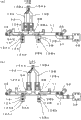
Fig. 2 is vertical view, front view and the right side view of the summary formation of the expression part relevant with the control lever 11 in the straight-bar machines that is located at Fig. 11.
Fig. 3 is that expression utilizes the vertical view after the straight-bar machines 1 of Fig. 1 carries out the simplification of plating-knitted state.
Fig. 4 is that expression utilizes the vertical view after the straight-bar machines 1 of Fig. 1 only carries out the simplification of state of braiding of plaiting.
Fig. 5 is the expression touchpad operation with the formation of gloves 40 as one of the cylindrical fabric of the straight-bar machines that can utilize Fig. 11 braiding routine outline elevation.
[label declaration]
1 straight-bar machines
2 needle-bars
3 tooth mouths
5,6 guide rails
7 cam carriers
9A master's yarn is used thread-carrier
9Ab master's yarn is used engaging recessed part
Thread-carrier is used in the 9B plaiting
Engaging recessed part is used in the 9Bb plaiting
11 control levers
12A master's yarn is used linkage pin
12Aa, 12Ba front end
Linkage pin is used in the 12B plaiting
14 bearings
15Aa master's yarn is used yarn-feeding port
Yarn-feeding port is used in the 15Ba plaiting
38 solenoids
40 touchpad operation are used gloves
41,42,43,44,45 plating-knitted portions
46 main yarns stop portion
The specific embodiment
Below, the summary as the straight-bar machines 1 of the embodiment of the utility model shown in Fig. 1~Fig. 4 constitutes an example of the cylindrical fabric that can weave shown in Fig. 5.Respectively among the figure, same to the part mark corresponding sometimes with reference to label with the part of explanation earlier, the explanation of omission repetition.In addition, also be utilized in sometimes as among the figure of description object not mark with reference to label, mention formerly the part that marks among the figure of explanation.
[embodiment]
As shown in Figure 1, in the straight-bar machines 1, needle-bar 2 is higher with tooth mouth 3 sides, along with the mode that reduces away from tooth mouth 3 is obliquely installed.Though the right-hand same needle-bar 2 that also is provided with in that the center line 3a with tooth mouth 3 becomes the figure of line symmetry has omitted diagram.Above needle-bar 2, with needle-bar 2 parallel cam carrier rail 4 and two sections guide rails 5,6 of being provided with.Through cam carrier rail 4, the cam carrier 7 that guiding moves back and forth on the direction perpendicular to paper along needle-bar 2.On the top of cam carrier 7 interlock unit 8 is installed.Interlock unit 8 utilizes guide rail 5,6, to be supported to the thread-carrier 9,10 that can move back and forth along direction perpendicular to paper switch respectively can with cam carrier 7 interlocks.
On the guide rail 5,, be provided with 2 main yarns and use thread-carrier 9B with thread-carrier 9A and plaiting as carrying out plating-knitted thread-carrier 9.Be for the positions relation of yarn thread-carrier for 2, for example plaiting becomes the front side of figure with thread-carrier 9B, and main yarn becomes the inboard of figure with thread-carrier 9A and hidden.The thread-carrier 10 of being located at guide rail 6 for example is used for the yarn of giving of thermal contraction yarn and elastomeric yarn etc.
Use the axial wood of cross sectional shape as circle in the guide rail 5,6, so thread-carrier 9,10 is provided with posture maintaining part 9a, 10a clips on the top of interlock unit 8 and posture holding member 5a that the top of cam carrier 7 is provided with, 6a and keep posture.
Control lever 11 also laterally arranges with guide rail 5.Interlock unit 8 collecting companys untie-sell 12,13, said linkage pin 12,13 by spring 18,19 with to the side-prominent modes of guide rail 5,6 application of force respectively.Control lever 11 is controlled with respect to the mode that the engaging recessed part 9b that is located at thread-carrier 9 haunts with the front end 12a in the face of the linkage pin 12 of thread-carrier 9.In addition, when control lever 11 is controlled haunting of linkage pins 12, carry out via bearing 14 rotary bodies such as grade.The periphery around rotation 14a rotation of bearing 14 contacts with control lever 11, utilizes the displacement of control lever 11 that linkage pin 12 is haunted with respect to engaging recessed part 9b.The front end 12a of linkage pin 12 is if the outstanding state that engages with engaging recessed part 9b that then becomes then becomes the state that does not engage as if submerging.The front end 13a of linkage pin 13 engages with the engaging recessed part 10b of thread-carrier 10.The overhang of linkage pin 12 is limited by banking pin 12b.
Be separately installed with on the thread-carrier 19,10 to yarn member 15,16, the said yarn member 15,16 of giving has the yarn-feeding port 15a that supplies with stocking yarn at front end.16a。In addition; Main yarn is given yarn member 15B with being respectively equipped with main yarn on the thread-carrier 9B with using for yarn member 15A and plaiting with thread-carrier 9A and plaiting, and said main yarn is with using yarn-feeding port 15Ba with having main yarn at front end for yarn member 15B with yarn-feeding port 15Aa and plaiting for yarn member 15A and plaiting.Like this, in the straight-bar machines 1, main yarn is configured in along on the same guide rail 5 that is provided with across tooth mouth 3 opposed a pair of needle-bars 2 with thread-carrier 9B with thread-carrier 9A and plaiting side by side.Below, in this manual, to same cross reference number mark A, B, and difference formation relevant with main yarn and the relevant formation with plaiting.To with the explanation of the common item of main yarn and plaiting, omit A, B and carry out.As carrying out plating-knitted condition, main yarn with thread-carrier 9A and plaiting with thread-carrier 9B when move with inboard this two direction the front side of paper, need the main yarn of transposing with yarn-feeding port 15Aa and plaiting context with yarn-feeding port 15Ba.Therefore, main yarn with give yarn member 15A and plaiting with to yarn member 15B when contacting on the yarn rail 5, be folded to the inboard together, main yarn can catch up with yarn-feeding port 15Aa and cross plaiting and use yarn-feeding port 15Ba.
Also be provided with bristle 17 on the cam carrier 7.On needle-bar 2, arranging the knitting needle 20 that is provided with is latch needles, utilizes needle latch to make the pinhock switching in the front end setting of tooth mouth 3 sides.Bristle 17 opens needle latch from the outside.On the needle-bar 2, between adjacent knitting needle 20, also be provided with sinker 21 with respect to tooth mouth 3 advance and retreat.Knitting needle 20 and sinker 21 are utilized in the knitting needle driving triangle 22 and the sinker driving triangle 23 that carry on the cam carrier 7 respectively and are driven.
Among Fig. 2, (a) and (b), (c) respectively from overlook, face, the summary of part that right flank is represented relevant controlling bar 11 constitutes.In the guide rail 5,6, utilize two sides of thread- carrier support unit 31,32 supporting axis directions respectively, be set up in the top of having omitted illustrated needle-bar 2.Control lever 11 is located at guide rail 5, between 6, is become one side of parallelogram connection-rod, can carry out with respect to guide rail 5 near the displacement that separates.And the static limit of this opposed parallelogram connection-rod in one side becomes cardinal extremity in the guide rail 5, pitman arm 35,36 can swingingly be supported on the part between the fulcrum of the link supporting parts 33,34 of the installed inside of thread-carrier support unit 31,32.Carrying out keying between the trip end of control lever 11 and pitman arm 35,36 closes.In addition, for guide rail 5,6 and control lever 11,, shorten and represent for the left and right directions of figure for the ease of explanation.
Control lever 11 carries out keying with the front end of connecting rod driver part 37 and closes near the right-hand member side.The cardinal extremity of connecting rod driver part 37 combines with the front end of the plunger of solenoid 38.Under the illustrated state, solenoid 38 outage utilizes spring energizedly to make plunger outstanding, and control lever 11 becomes the state near guide rail 5.Under this state, the main yarn of being located at interlock unit 8 is side-prominent to guide rail 5 with the application of force that the front end 12Aa of linkage pin 12A utilizes spring 18A to produce.The plaiting of not accepting the control of control lever 11 also utilizes the application of force that is produced by spring 18B, 19 side-prominent to guide rail 5 with front end 12Ba, the 13a of linkage pin 12B and linkage pin 13.Main yarn with on linkage pin 12B and the linkage pin 13, is respectively equipped with the banking pin 12Ab, 12Bb, the 13b that are used to limit overhang with linkage pin 12A, plaiting.Owing to for the part of utilizing the main yarn of control lever 11 control to contact with haunting of linkage pin 12A is provided with bearing 14, even so main yarn move with linkage pin 12A and cam carrier 7 interlocks, also can successfully keep in touch state.In addition, can not reduce contact resistance, then can not use bearing 14 yet, with the part of linkage pin 12A contact portion is set, or the member of contact usefulness is set at main yarn if do not rotate yet.
Fig. 3 representes to use main yarn to carry out plating-knitted state with thread-carrier 9A and plaiting with thread-carrier 9B.For example as shown in the figure; Main yarn is being disposed at the left side with thread-carrier 9A; Plaiting is disposed at thread-carrier 9B under the situation on right side, and plaiting is moved earlier with thread-carrier 9B when the right lateral 15R shown in Fig. 3 (a), and master's yarn moves earlier with thread-carrier 9A when the left lateral 15L shown in Fig. 3 (b).But main yarn all is that main yarn moves earlier with yarn-feeding port 15Aa with in yarn-feeding port 15Aa and the position relation of plaiting with yarn-feeding port 15Ba at both direction.Among Fig. 3 (a), on one side become main yarn with thread-carrier 9A and plaiting with thread-carrier 9B on one side to plaiting with the configuration direction side interlock of thread-carrier 9B keep being scheduled near distance near state.Among Fig. 3 (b), on one side become the released state of the separating distance that main yarn keeps with the configuration direction side interlock of thread-carrier 9A being scheduled to main yarn with thread-carrier 9B with thread-carrier 9A and plaiting on one side.Main yarn is outstanding with two sides' of linkage pin 12B front end 12Aa, 12Ba with linkage pin 12A and plaiting; Engage with engaging recessed part 9Bb with engaging recessed part 9Ab and plaiting with main yarn respectively, become make main yarn with thread-carrier 9A and plaiting with this two side of thread-carrier 9B state of interlock simultaneously.In addition, main yarn is contained in interlock unit 8 with linkage pin 12A and plaiting with linkage pin 12B, so the distance between the center line 12Ac, 12Bc is retained as necessarily.If make main yarn with thread-carrier 9A and plaiting with reciprocal cam carrier 7 interlocks of walking of thread-carrier 9B, poor and supply with main yarn and plaiting before and after being provided with, switch the needle-bar of front and back corresponding to direction of travel, then cylindrical fabric is carried out plating-knitted.
Fig. 4 will make main yarn stop with thread-carrier 9A, and the state reduction of only using plaiting to carry out the braiding of knitted fabric with thread-carrier 9B is represented.If make solenoid 38 for "on" position attracts plunger, then connecting rod driver part 37 also is pulled, and control lever 11 separates from guide rail 5.Main yarn becomes the state of submerging with linkage pin 12A via bearing 14, and front end 12Aa is disengaged with the state that engaging recessed part 9Ab engages with main yarn.Plaiting is with among the thread-carrier 9B, and all independent interlock of the left lateral 15BL shown in the right lateral 15BR shown in Fig. 4 (a) and Fig. 4 (b) can only use the braiding of plaiting.
Shown in Fig. 3 (a), main yarn with linkage pin 12A and plaiting with linkage pin 12B front end 12Aa, 12Ba respectively with state that main yarn engages with engaging recessed part 9Bb with engaging recessed part 9Ab and plaiting under with the wall butt of the both sides of interlock direction.Shown in Fig. 4 (a), establish this front end 12Aa, 12Ba two side portions be spaced apart dA, dB the time, main yarn is bigger with linkage pin 12B one side's interval dB than plaiting with linkage pin 12A one side's interval dA.In addition, main yarn with engaging recessed part 9Ab and plaiting with among the engaging recessed part 9Bb, between the wall of the both sides of interlock direction apart from sA, sB be plaiting with engaging recessed part 9Bb one side greater than main yarn with engaging recessed part 9Ab one side.Consequently; Compare corresponding to the distance that the interlock direction can move with the front end 12Aa of the main yarn in the engaging recessed part 9Ab with main yarn with linkage pin 12A, plaiting with engaging recessed part 9Bb in plaiting bigger with the front end 12Ba of linkage pin 12B corresponding to the distance that the interlock direction can move.In plating-knitted,,, the summit that becomes the triangle of comparing the mountain type in the scope of the shoulder of row side, need compare main yarn carries out plaiting away from the position on summit the yarn of giving after leaning on respect to driven the knitting needle 20 that triangle 22 drives by knitting needle.Through increasing the moving range of plaiting,, also can utilize sufficient front and back difference to carry out the yarn of giving of the plaiting relative with main yarn even switch the interlock direction with thread-carrier 9B.
Fig. 5 representes that the electrostatic capacity type touchpad operation constitutes the example as the cylindrical fabric that on straight-bar machines 1, can weave with the summary of gloves 40.The stocking yarn that touchpad operation is used electric conductivity with gloves 40 is provided with plating-knitted 41,42,43,44,45 as main yarn at finger tip.This gloves open from the front end that refers to bag; Therefore, each weaves plating-knitted 41,42,43,44,45 respectively when referring to opening of bag; Main yarn is stopped, if from referring to beginning of bag midway, then with stopping portion's 46 braidings as main yarn after the tube portion with thread-carrier 9A is as shown in Figure 4.In addition, in the part of wrist, insert elastomeric yarn and form lastex insertion section 47.Through only being provided with plating-knitted 41,42,43,44,45, can reduce the use amount of the stocking yarn of electric conductivity at high price in this necessary part.
In addition,, therefore use main yarn with carry out plating-knitted of thread-carrier 9A with stop, can weaving decorations such as having style, the knitted fabric of multiple functions such as anti-skidding thing such as concavo-convex through switching because main yarn exposes to the surface of knitted fabric.
Claims (3)
1. straight-bar machines, it can utilize the plating-knitted knitted cylindrical fabric that comes, along on the same guide rail that is provided with across the opposed a pair of needle-bar of tooth mouth, main yarn with thread-carrier and plaiting with thread-carrier this 2 thread-carriers and row arrangement,
Saidly plating-knittedly do; With regard to main yarn with the main yarn of thread-carrier with yarn-feeding port and plaiting with the plaiting of thread-carrier with regard to the position of yarn-feeding port; The released state of the separating distance that keeps with the configuration direction interlock of thread-carrier to main yarn at 2 thread-carriers being scheduled to, and 2 thread-carriers to plaiting keep with the configuration direction interlock of thread-carrier being scheduled near distance near under the state; All be that main yarn moves earlier with yarn-feeding port with respect to plaiting with yarn-feeding port; Cam carrier makes 2 thread-carrier interlocks and supplies with main yarn and plaiting in this way, and said straight-bar machines is characterised in that, comprising:
Main yarn is used linkage pin with linkage pin and plaiting, in the face of this guide rail, the overhead standard width of a room in an old-style house of direction of travel at a distance from and be located at cam carrier, engage with thread-carrier with thread-carrier and plaiting with main yarn respectively and can interlock;
Control lever laterally arranges with this guide rail, can carry out with respect to of the displacement of guide rail near separation,
Be respectively equipped with main yarn with thread-carrier and plaiting on thread-carrier at main yarn and use engaging recessed part with engaging recessed part and plaiting; This main yarn engages with linkage pin with linkage pin and plaiting with main yarn with engaging recessed part with engaging recessed part and plaiting; Has the wall that supplies the linkage pin butt in the both sides of interlock direction
Utilize the displacement of control lever with respect to the guide rail, main yarn can switch the state of engaging and the state that do not engage with respect to main yarn with engaging recessed part with linkage pin.
2. straight-bar machines according to claim 1 is characterized in that,
Said main yarn with linkage pin and said plaiting with linkage pin respectively with state that said main yarn engages with engaging recessed part with engaging recessed part and said plaiting under; With the part of the wall butt of the both sides of said interlock direction be that main yarn is bigger with linkage pin one side than plaiting with linkage pin one side at interval
Main yarn is that plaiting is bigger with engaging recessed part one side than main yarn with engaging recessed part one side with engaging recessed part and plaiting with the distance between the wall of the both sides of this interlock direction of engaging recessed part.
3. straight-bar machines according to claim 1 and 2 is characterized in that,
Be provided with rotary body at said main yarn on linkage pin,
The periphery of the rotation of this rotary body contacts with said control lever, utilizes the displacement of this control lever, and main yarn haunts with engaging recessed part with respect to said main yarn with linkage pin,
If main yarn outstanding with engaging recessed part with respect to main yarn, then becomes the state of said engaging with linkage pin, if submerge with engaging recessed part with respect to main yarn, then becomes the said state that does not engage.
Applications Claiming Priority (2)
| Application Number | Priority Date | Filing Date | Title |
|---|---|---|---|
| JP2011-012402 | 2011-01-24 | ||
| JP2011012402A JP2012153990A (en) | 2011-01-24 | 2011-01-24 | Flat-knitting machine |
Publications (1)
| Publication Number | Publication Date |
|---|---|
| CN202492680U true CN202492680U (en) | 2012-10-17 |
Family
ID=46836020
Family Applications (1)
| Application Number | Title | Priority Date | Filing Date |
|---|---|---|---|
| CN2012200247087U Expired - Lifetime CN202492680U (en) | 2011-01-24 | 2012-01-18 | Flat knitting machine |
Country Status (3)
| Country | Link |
|---|---|
| JP (1) | JP2012153990A (en) |
| KR (1) | KR200477296Y1 (en) |
| CN (1) | CN202492680U (en) |
Families Citing this family (3)
| Publication number | Priority date | Publication date | Assignee | Title |
|---|---|---|---|---|
| CN103572491A (en) * | 2013-10-29 | 2014-02-12 | 绍兴市强生精机制造有限公司 | Yarn nozzle seat locating structure of fully computerized glove knitting machine |
| KR20160111139A (en) | 2015-03-16 | 2016-09-26 | 이기석 | Identification Display for Terminal Block |
| JP7425006B2 (en) * | 2020-02-17 | 2024-01-30 | 株式会社島精機製作所 | How to knit knitted fabric |
Family Cites Families (4)
| Publication number | Priority date | Publication date | Assignee | Title |
|---|---|---|---|---|
| JP2602156B2 (en) * | 1992-11-09 | 1997-04-23 | 株式会社島精機製作所 | Knitted fabric presser for flat knitting machine |
| TW483962B (en) * | 2000-02-29 | 2002-04-21 | Shima Seiki Mfg | Method of knitting plating of tubular knitting fabric by four-sheet bed weft knifting machine |
| KR100461529B1 (en) * | 2002-07-08 | 2004-12-17 | 쌍용기계공업주식회사 | Electronic automatic striping unit of jacquard circular knitting machine |
| WO2006132376A1 (en) * | 2005-06-10 | 2006-12-14 | Shima Seiki Manufacturing Limited | Weft knitting machine with stitch presser and method of controlling the same |
-
2011
- 2011-01-24 JP JP2011012402A patent/JP2012153990A/en active Pending
- 2011-12-12 KR KR2020110010979U patent/KR200477296Y1/en not_active Expired - Lifetime
-
2012
- 2012-01-18 CN CN2012200247087U patent/CN202492680U/en not_active Expired - Lifetime
Also Published As
| Publication number | Publication date |
|---|---|
| KR200477296Y1 (en) | 2015-05-28 |
| KR20120005539U (en) | 2012-08-01 |
| JP2012153990A (en) | 2012-08-16 |
Similar Documents
| Publication | Publication Date | Title |
|---|---|---|
| CN101310056B (en) | Flat knitting machine capable of inserting warp and knitting method in the flat knitting machine | |
| CN102264962B (en) | Method for preventing ravel of knitting yarn and knitted fabric | |
| CN102859057B (en) | Method of joining adjacent knitted fabric parts and knitted fabric | |
| CN1323205C (en) | Knitting method and knitting program generating device for intarsia pattern knitted fabric | |
| CN104420069B (en) | Flat knitting machine with yarn guides movable transversely to the needle bed | |
| CN103882613A (en) | Method For Preventing Unraveling Of Knitting Yarn | |
| CN101680141B (en) | Stripe pattern knitting device and method in yarn feeding switching machine | |
| CN201971985U (en) | Cleaner | |
| TWI306481B (en) | Engaging member, striping attachment, and circular knitting machine | |
| CN101858010A (en) | Flat knitting machine for knitting tubular knitted fabric | |
| CN109610081B (en) | Needle-collecting type composite knitted fabric and knitting method thereof | |
| CN201952595U (en) | Knitting machine with spandex yarn switching devices | |
| CN102140725B (en) | Plating knitting method | |
| CN103320954A (en) | Opening forming and sealing mechanism of knitting machine | |
| CN101096794A (en) | Retreating method for knitting yarn and flat knitting machine | |
| CN107142601A (en) | The weaving method of cylindrical fabric | |
| CN203715861U (en) | Circular pantyhose weft knitting machine with automatic pantyhose width marking yarn cutter | |
| CN203113042U (en) | Electronic crochet machine | |
| CN202369751U (en) | Yarn feeder device for flat knitting machine | |
| CN201588062U (en) | Multiple layer warp insertion and weft insertion woven and knitted composite structure and its yarn feeding device | |
| JP2012153990A (en) | Flat-knitting machine | |
| CN102061558B (en) | Braiding machine equipped with spandex yarn switching device | |
| CN101581008B (en) | Multilayer even laid-in weaving and knitting composite structure, weaving method thereof | |
| CN201208778Y (en) | Textile machine | |
| CN103306029A (en) | Method for preventing ravel of knitting yarn |
Legal Events
| Date | Code | Title | Description |
|---|---|---|---|
| C14 | Grant of patent or utility model | ||
| GR01 | Patent grant | ||
| CX01 | Expiry of patent term | ||
| CX01 | Expiry of patent term |
Granted publication date: 20121017 |