CN202719210U - a check valve - Google Patents
a check valve Download PDFInfo
- Publication number
- CN202719210U CN202719210U CN 201220354088 CN201220354088U CN202719210U CN 202719210 U CN202719210 U CN 202719210U CN 201220354088 CN201220354088 CN 201220354088 CN 201220354088 U CN201220354088 U CN 201220354088U CN 202719210 U CN202719210 U CN 202719210U
- Authority
- CN
- China
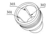
- Prior art keywords
- spool
- check valve
- valve seat
- opening
- valve
- Prior art date
- Legal status (The legal status is an assumption and is not a legal conclusion. Google has not performed a legal analysis and makes no representation as to the accuracy of the status listed.)
- Expired - Fee Related
Links
- 239000002184 metal Substances 0.000 claims description 3
- 229910052751 metal Inorganic materials 0.000 claims description 3
- 238000007789 sealing Methods 0.000 claims description 3
- 238000004519 manufacturing process Methods 0.000 abstract description 16
- 239000000463 material Substances 0.000 abstract description 8
- 238000000034 method Methods 0.000 abstract description 7
- 230000000694 effects Effects 0.000 abstract description 4
- 230000006978 adaptation Effects 0.000 abstract 2
- 239000012530 fluid Substances 0.000 description 23
- 230000003044 adaptive effect Effects 0.000 description 10
- 239000007787 solid Substances 0.000 description 6
- 239000004568 cement Substances 0.000 description 2
- 238000001746 injection moulding Methods 0.000 description 2
- 229910001369 Brass Inorganic materials 0.000 description 1
- 229910001018 Cast iron Inorganic materials 0.000 description 1
- 239000010951 brass Substances 0.000 description 1
- -1 cast iron Chemical class 0.000 description 1
- 150000002739 metals Chemical class 0.000 description 1
- 229910001220 stainless steel Inorganic materials 0.000 description 1
- 239000010935 stainless steel Substances 0.000 description 1
- 230000009466 transformation Effects 0.000 description 1
Images


Landscapes
- Check Valves (AREA)
Abstract
The utility model discloses a check valve, including a disk seat, one with the opening adaptation of disk seat and establish the case on the opening, one is connected and plays the guide sleeve of guide effect to the case with the disk seat upper end, the case by a spherical crown structure and one with the opening adaptation of spherical crown structure and connect integrative hollow cylinder to constitute, the external diameter of spherical crown structure opening part is the same with the hollow cylinder external diameter, can integrated into one piece, save material during production, need not carry out subsequent processing moreover, simplified the production and processing process of case.
Description
Technical field
The utility model relates to a kind of device with return-stopping function, particularly a kind of check valve.
Background technique
Often use check valve carrying on the pipeline of fluid, existing check valve is provided with valve seat and spool, by cooperating of valve seat and spool, can realize making fluid only to flow and stop the return-stopping function of fluid refluence to a direction.Spool is to realize the important member of return-stopping function, existing spool is solid sphere, because the one-body molded injection moulding of solid sphere out afterwards can be because of expanding with heat and contract with cold, easily be out of shape and surface irregularity in process of production, the general normally use of processing that after production, also needs minimum 2 procedures, manufacture operation more loaded down with trivial details, and solid sphere comparison consume material, cost of production improved.
Therefore, how to realize that a kind of spool can be one-body molded and save material, the simple check valve of production and processing operation is the technical problem that needs to be resolved hurrily in the industry simultaneously.
Summary of the invention
Main purpose of the present utility model provides a kind of check valve, is intended to make the spool can be one-body molded when producing and save material, simplifies simultaneously the production and processing operation of spool.
The utility model proposes a kind of check valve, comprise a valve seat, one and the opening of valve seat adaptive and be located at spool on the opening, one pilot sleeve that is connected with valve seat upper end and spool is play the guiding role, spool is made of a spherical cap structure and a hollow cylinder adaptive with the opening of spherical cap structure and that be connected, and the external diameter of spherical cap structure opening is identical with the hollow cylinder external diameter.
Preferably, valve base inner wall face and pilot sleeve lower end outer wall are threaded connection fixing.
Preferably, the pilot sleeve internal face evenly is provided with some spools that make and moves axially and identical rib not turning or that move radially in pilot sleeve, the thickness of the Thickness Ratio end portion of rib upper end part is large, the internal diameter of office, the inherent rib underpart of pilot sleeve is identical with the diameter of spool, and is less than the diameter of spool at the internal diameter of office, rib upper end portion.
Preferably, be provided with a chimb in the valve seat, chimb is provided with a seal ring adaptive with spool, and after pilot sleeve and valve seat were spirally connected, pilot sleeve pressed seal ring and chimb fixing.
Preferably, the hollow cylinder height is not less than 1 centimetre, and the whole height of spool is less at least 1 centimetre than the length of the end portion of rib simultaneously.
Preferably, the diameter of spool is not less than 2 centimetres.
Preferably, the thickness of spool is not less than 0.3 centimetre.
Preferably, spool is made by plastic cement or metal.
Preferably, the side of valve seat end portion and bottom surface are provided with some through holes equably.
The utility model check valve comprise a valve seat, one and the opening of valve seat adaptive and be located at spool on the opening, one pilot sleeve that is connected with valve seat upper end and spool is play the guiding role, spool is made of a spherical cap structure and a hollow cylinder adaptive with the opening of spherical cap structure and that be connected, the external diameter of spherical cap structure opening is identical with the hollow cylinder external diameter, can be one-body molded during production, save material, and do not need to carry out following process, simplified the production and processing operation of spool.
Description of drawings
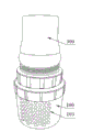
Fig. 1 is an embodiment's of a kind of check valve of the utility model stereogram;
Fig. 2 is an embodiment's of a kind of check valve of the utility model side sectional view;
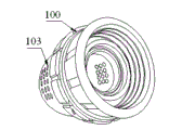
Fig. 3 is the stereogram of valve seat among the embodiment of a kind of check valve of the utility model;
Fig. 4 is the stereogram of spool among the embodiment of a kind of check valve of the utility model;
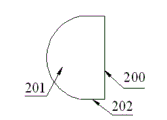
Fig. 5 is the side view of spool among the embodiment of a kind of check valve of the utility model;
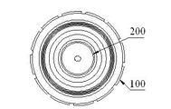
Fig. 6 is the plan view that spool is put into valve seat among the embodiment of a kind of check valve of the utility model;
Fig. 7 is the stereogram of pilot sleeve among the embodiment of a kind of check valve of the utility model.
The realization of the utility model purpose, functional characteristics and advantage are described further with reference to accompanying drawing in connection with embodiment.
Embodiment
Should be appreciated that specific embodiment described herein only in order to explaining the utility model, and be not used in restriction the utility model.
Referring to figs. 1 through Fig. 7, an embodiment of a kind of check valve of the present utility model is proposed, comprise valve seat 100, spool 200, pilot sleeve 300.The side of valve seat 100 end portions and bottom surface are provided with some through holes 103 equably, and fluid enters the valve seat 100 from through hole 103.Spool 200 is adaptive and be arranged on the opening with the opening of valve seat 100, valve seat 100 internal faces are provided with screw thread, and the outer wall of pilot sleeve 300 lower ends is provided with corresponding adaptive screw thread, pilot sleeve 300 and valve seat 100 are threaded connection fixing, and pilot sleeve 300 upper end open are connected and fixed by the outside thread of internal thread and an output duct.
Be provided with a chimb 101 in the valve seat 100, chimb 101 is annular nib, chimb 101 is provided with a seal ring 102, the central opening of seal ring 102 and described spool 200 are adaptive, after pilot sleeve 300 is spirally connected with valve seat 100, pilot sleeve 300 is closely fixing with seal ring 102 and chimb 101, makes seal ring 102 reach good sealing effect.Chimbs 101 in valve seat 100 and the valve seat 100 structure that is formed in one is produced easily easy.
Spool 200 is adaptive with the central opening of valve seat 100 inner seal rings 102, and is arranged on the seal ring 102 and with seal ring 102 and fits tightly.By cooperating of valve seat 100 and spool 200, can realize the return-stopping function that makes fluid only flow and stop fluid to flow backwards to a direction.Fluid flows to guiding sleeve 300 directions from valve seat 100, the thrust that spool 200 is subjected to fluid in pilot sleeve 300 up the mobile fluid that makes can up flow and continue to flow toward pilot sleeve 300 outlet ports by spool 200 edges from the valve seat mouth, finally discharge from output duct, and the upper end part 302 of pilot sleeve 300 interior ribs 301 stops spool 200 to continue the up opening of mobile clogging pilot sleeve 300.When fluid stops up to spring up, at the fluid of spool 200 upper ends under the effect of the self gravitation of the pressure of current downflow and spool 200, spool 200 falls back on the seal ring 102 in the valve seat 100 and with seal ring 102 and fits tightly, thereby cut off flowing of spool 200 lower end fluids, then can realize return-stopping function.
When the fluid pressure at the fluid pressure specific output conduit place at valve seat 100 places is powerful, fluid enters in the valve seat 100 and toward the output duct direction from through hole 103 and flows, when fluid up flows in valve seat 100, being positioned over spool 200 on the valve seat 100, to be subject to the thrust of fluid up mobile in pilot sleeve 300, making fluid up flow from the opening of valve seat 100 and to continue past pilot sleeve 300 outlet ports by spool 200 edges flows, finally discharge from output duct, and the upper end part 302 of pilot sleeve 300 interior ribs 301 stops spool 200 to continue the up opening of mobile clogging pilot sleeve 300; When the fluid pressure at valve seat 100 places is powerful unlike the fluid pressure at output duct place, at the fluid of spool 200 upper ends under the effect of the self gravitation of the pressure of current downflow and spool 200, spool 200 falls back on the seal ring 102 in the valve seat 100, thereby cut off flowing of spool 200 lower end fluids, realized the return-stopping function that prevents that fluid from flowing backwards.
Existing spool is solid sphere, because the one-body molded injection moulding of solid sphere out afterwards can be because of expanding with heat and contract with cold, easily be out of shape and surface irregularity in process of production, the general normally use of processing that after production, also needs minimum 2 procedures, manufacture operation more loaded down with trivial details, and solid sphere comparison consume material, improved cost of production; And spool 200 of the present utility model is made of a spherical cap structure 201 and a hollow cylinder 202 adaptive with the opening of spherical cap structure 201 and that be connected, the external diameter of spherical cap structure 201 openings is identical with hollow cylinder 202 external diameters, can be one-body molded during production, save material, simplified simultaneously the production and processing operation of spool.The material of spool 200 can be selected plastic cement, and perhaps the metals such as cast iron, stainless steel and brass can be selected according to actual conditions.Hollow cylinder 202 highly is not less than 1 centimetre, and the whole height of spool 200 is less at least 1 centimetre than the length of the end portion 303 of rib 301 simultaneously; The diameter of spool 200 is not less than 2 centimetres, is generally between 2 centimetres to 20 centimetres; The thickness of spool 200 is not less than 0.3 centimetre, is generally between 0.3 centimetre to 2 centimetres.
The above only is preferred embodiment of the present utility model; be not so limit claim of the present utility model; every equivalent structure transformation that utilizes the utility model specification and accompanying drawing content to do; or directly or indirectly be used in other relevant technical fields, all in like manner be included in the scope of patent protection of the present utility model.
Claims (9)
Priority Applications (1)
| Application Number | Priority Date | Filing Date | Title |
|---|---|---|---|
| CN 201220354088 CN202719210U (en) | 2012-07-20 | 2012-07-20 | a check valve |
Applications Claiming Priority (1)
| Application Number | Priority Date | Filing Date | Title |
|---|---|---|---|
| CN 201220354088 CN202719210U (en) | 2012-07-20 | 2012-07-20 | a check valve |
Publications (1)
| Publication Number | Publication Date |
|---|---|
| CN202719210U true CN202719210U (en) | 2013-02-06 |
Family
ID=47621034
Family Applications (1)
| Application Number | Title | Priority Date | Filing Date |
|---|---|---|---|
| CN 201220354088 Expired - Fee Related CN202719210U (en) | 2012-07-20 | 2012-07-20 | a check valve |
Country Status (1)
| Country | Link |
|---|---|
| CN (1) | CN202719210U (en) |
Cited By (2)
| Publication number | Priority date | Publication date | Assignee | Title |
|---|---|---|---|---|
| CN105874252A (en) * | 2014-01-02 | 2016-08-17 | 耆那灌溉系统有限公司 | Non return valve for use in water line |
| CN109114264A (en) * | 2018-10-11 | 2019-01-01 | 梧州市旺捷机械制造有限公司 | It is a kind of on bottle placer without spring non-return valve |
-
2012
- 2012-07-20 CN CN 201220354088 patent/CN202719210U/en not_active Expired - Fee Related
Cited By (2)
| Publication number | Priority date | Publication date | Assignee | Title |
|---|---|---|---|---|
| CN105874252A (en) * | 2014-01-02 | 2016-08-17 | 耆那灌溉系统有限公司 | Non return valve for use in water line |
| CN109114264A (en) * | 2018-10-11 | 2019-01-01 | 梧州市旺捷机械制造有限公司 | It is a kind of on bottle placer without spring non-return valve |
Similar Documents
| Publication | Publication Date | Title |
|---|---|---|
| CN111038842B (en) | A kind of all-plastic foam pump | |
| CN102207215B (en) | Water-saving non-return valve | |
| CN108837958B (en) | Water separator | |
| CN203462529U (en) | Discharge element | |
| CN202719210U (en) | a check valve | |
| CN211495185U (en) | Full plastic foam pump | |
| CN201137728Y (en) | Air pumping valve | |
| CN103707545B (en) | Hollow active carbon forming die | |
| CN204387343U (en) | A kind of novel triangle vavle assembly | |
| CN202203443U (en) | High-charging-port three-way valve with guiding throttling device | |
| CN205446832U (en) | A pipeline explosion-proof device and explosion-proof valve | |
| CN203384429U (en) | Reverse flow stopping device of air-solution mixing chamber | |
| CN203940073U (en) | A kind of clamp mute check-valve | |
| CN203248762U (en) | Exhaust valve of irrigation pipeline | |
| CN203614826U (en) | Stacked unidirectional valve | |
| CN202062609U (en) | Hot runner valve needle guide sleeve structure | |
| CN220249013U (en) | Stacked valve core cup seat | |
| CN202834187U (en) | Self-switching pressure stabilizing three-way flow divider | |
| CN202278026U (en) | Punch-die core for high-density plate die | |
| CN204692618U (en) | A kind of core member of gas ratio valve | |
| CN202343611U (en) | Male mould positioning plate for dense plate mould | |
| CN201250914Y (en) | Ceramic chip sealing water tap | |
| CN202877359U (en) | Reinforced concave-convex mold core for thick plate mold of filter cleaner | |
| CN206929379U (en) | A kind of push button tap | |
| CN218670710U (en) | Integrally formed anti-leakage valve body |
Legal Events
| Date | Code | Title | Description |
|---|---|---|---|
| C14 | Grant of patent or utility model | ||
| GR01 | Patent grant | ||
| CF01 | Termination of patent right due to non-payment of annual fee | ||
| CF01 | Termination of patent right due to non-payment of annual fee |
Granted publication date: 20130206 Termination date: 20210720 |