CN203473137U - Scooter frame assembly - Google Patents
Scooter frame assembly Download PDFInfo
- Publication number
- CN203473137U CN203473137U CN201320390615.0U CN201320390615U CN203473137U CN 203473137 U CN203473137 U CN 203473137U CN 201320390615 U CN201320390615 U CN 201320390615U CN 203473137 U CN203473137 U CN 203473137U
- Authority
- CN
- China
- Prior art keywords
- neck
- frame assembly
- neck portions
- tubular
- tubular neck
- Prior art date
- Legal status (The legal status is an assumption and is not a legal conclusion. Google has not performed a legal analysis and makes no representation as to the accuracy of the status listed.)
- Expired - Lifetime
Links
- 238000009434 installation Methods 0.000 description 2
- 230000009286 beneficial effect Effects 0.000 description 1
- 239000004020 conductor Substances 0.000 description 1
- 238000000151 deposition Methods 0.000 description 1
- 230000007774 longterm Effects 0.000 description 1
- 238000000034 method Methods 0.000 description 1
- 238000012986 modification Methods 0.000 description 1
- 230000004048 modification Effects 0.000 description 1
- 230000035939 shock Effects 0.000 description 1
Images


Landscapes
- Automatic Cycles, And Cycles In General (AREA)
Abstract
The utility model provides a scooter frame assembly, and particularly, the scooter frame assembly comprises a pedal frame part and a neck part, wherein the pedal frame part comprises two or multiple tubular pedal parts, and the neck part comprises multiple tubular neck parts. The scooter frame assembly is reasonable in structure, uniform in stressing, not easily deformed and good in safety and has great application value.
Description
Technical field
The present invention relates to sports equipment field, particularly, the present invention relates to a kind of Kickboard Scooter frame assembly.
Background technology
At present, along with popularizing of sports, Kickboard Scooter is familiar with by people.At present, the framework of most of Kickboard Scooters is to be all formed by connecting by a plurality of parts.In the use procedure of Kickboard Scooter, due to stressed frequent, damaging usually appears in the connecting portion of connecting portion, particularly head tube and pedal.If user is miss in use, easily user is damaged.Therefore, this area still lacks a kind of scooter frame structure that can strengthen scooter connecting portion intensity.
Summary of the invention
The object of this invention is to provide a kind of rational in infrastructure, stressed evenly, not yielding, the Kickboard Scooter frame assembly that safety performance is good.
A first aspect of the present invention, provides a kind of Kickboard Scooter frame assembly, and described Kickboard Scooter frame assembly comprises:
Footrest frame portion (310), wherein said footrest frame portion comprises two or more tubulose tread elements; With
Neck (320), wherein said neck comprises two or more tubular neck portions parts.
In another preference, described neck comprises two to five tubular neck portions parts.
In another preference, described footrest frame portion comprises two tubulose tread elements.
In another preference, described footrest frame portion comprises one first tubulose tread elements (312) and one second tubulose tread elements (314).
In another preference, described first, second tubulose tread elements is linear.
In another preference, described the first tubulose tread elements is " > " shape, and described the second tubulose tread elements is " < " shape.
In another preference, described footrest frame portion also comprises optional one or more support tubes.
In another preference, described support tube is that " C " shape of protrusion downwards is managed or " [" shape is managed, and below pedal, forms a support.
In another preference, described neck comprises:
Head tube (324);
The first tubular neck portions part (321);
The second tubular neck portions part (322); With
The 3rd tubular neck portions part (323);
And described tubular neck portions part is used for connecting described head tube and described footrest frame portion 310.
In another preference, described neck also comprises one or more base portion.
In another preference, described neck comprises 1~3 base portion.
In another preference, described neck comprises one first base portion and one second base portion.
In another preference, described the second base portion is positioned at the below of the first base portion.
In another preference, one end of described the first tubular neck portions part (321) is connected with described head tube (324), and the other end is connected with the second tubulose tread elements (314) with described base portion (326);
One end of described the second tubular neck portions part (322) is connected with described head tube (324), and the other end is connected with described base portion (326);
One end of described the 3rd tubular neck portions part (323) is connected with described head tube (324), and the other end is connected with base portion (326) with described the first tubulose tread elements (312).
In another preference, described frame assembly is Segway Human Transporter frame assembly.
In another preference, on described frame assembly, also comprise an on and off switch, described on and off switch is in use opening or cut out Segway Human Transporter.
In should be understood that within the scope of the present invention, above-mentioned each technical characterictic of the present invention and can combining mutually between specifically described each technical characterictic in below (eg embodiment), thus form new or preferred technical scheme.As space is limited, at this, tire out and state no longer one by one.
Accompanying drawing explanation
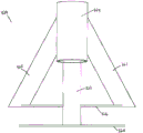
Fig. 1 is the back view of the Kickboard Scooter frame assembly of one embodiment of the invention;
Fig. 2 is the top view of the Kickboard Scooter frame assembly of one embodiment of the invention;
Fig. 3 is the front elevation of the Kickboard Scooter frame assembly of one embodiment of the invention;
Fig. 4 is the right elevation of the Kickboard Scooter frame assembly of one embodiment of the invention;
Fig. 5 is the top view of neck of the Kickboard Scooter of one embodiment of the invention;
Fig. 6 is the top view of neck of the Kickboard Scooter of one embodiment of the invention;
Fig. 7 has shown the front elevation of neck of the Kickboard Scooter of one embodiment of the invention;
Fig. 8 has shown the right elevation of the neck of the Kickboard Scooter in one embodiment of the invention;
Fig. 9 has shown the back view of the neck of the Kickboard Scooter in one embodiment of the invention;
Figure 10 has shown the back view of the neck of the Kickboard Scooter in one embodiment of the invention;
Figure 11 has shown the top view of the tube neck of the Kickboard Scooter in one embodiment of the invention;
Figure 12 has shown the left view of the tube neck of the Kickboard Scooter in one embodiment of the invention;
Figure 13 has shown the back view of the tube neck of the Kickboard Scooter in one embodiment of the invention;
Figure 14 has shown the front elevation of the tube neck of the Kickboard Scooter in one embodiment of the invention;
Figure 15 has shown the top view of the tube neck of the Kickboard Scooter in one embodiment of the invention.
The specific embodiment
The inventor, through long-term and deep research, has designed a kind of Kickboard Scooter framework, and described Kickboard Scooter framework can increase the intensity of Kickboard Scooter effectively, and can or seldom can not bring inconvenience to user.
The invention provides a kind of Kickboard Scooter framework, wherein said framework comprises pedal, neck, and a head tube, and wherein, described neck comprises the tubular member of two or more connection pedals and head tube.
Fig. 1 has shown the back view of the Kickboard Scooter frame assembly 300 of one embodiment of the present of invention, and described frame assembly comprises a footrest frame portion 310 and neck 320.
Preferably, described footrest frame portion can also comprise one or more support tube, and described support tube is roughly parallel to described tubulose tread elements 312 and 314, and slightly thinner than described tubulose tread elements, for increasing the firm degree of described tread portion.In another preference, described support tube can for " C " shape pipe of protruding downwards or " [" shape pipe, thus below pedal, form a support, for placing articles or hold battery.
Neck 320 comprises the first tubular neck portions part 321, the second tubular neck portions part 322, the three tubular neck portions parts 323, head tube 324, and a base portion 326.Described first, second, third tubular neck portions part can be used for connecting head tube 324, base portion 326, the first tubulose tread elements 312 and the second tubulose tread elements 314.
Wherein, described head tube 324 can be connected with the miscellaneous part of Kickboard Scooter, as steering tube, handle assembly etc.In another preference, between described head tube 324 and miscellaneous part, by removable fasteners, be connected.
In a preference of the present invention, one end of the first tubular neck portions part 321 is connected with head tube 324, and the other end is connected with the second tubulose tread elements 314 with described base portion 326; One end of the second tubular neck portions part 322 is connected with head tube 324, and the other end is connected with described base portion 326.One end of the 3rd tubular neck portions part 323 is connected with head tube 324, and the other end is connected with base portion 326 with described the first tubulose tread elements 312.
In another preference, described neck structure is that triangle connects, thereby has good intensity and shock resistance.
As shown in Figure 1, the first tubulose tread elements 312, the second tubulose tread elements 314, the first tubular neck portions part 321, the second tubular neck portions parts 322, and the 3rd tubular neck portions part 323 comprises respectively substantially tubular cross-sectional plane.In other embodiments, the first tubulose tread elements 312, the second tubulose tread elements 314, the first tubular neck portions parts 321, the second tubular neck portions part 322, and the cross-sectional plane of the 3rd tubular neck portions part 323 can be any other shape, as square, triangle, rectangle, ellipse.Each described tubular assembly can have identical shape of cross section, also can have different shape of cross sections.
In another preference, described tubular structure inside has enough spaces, can be for depositing the battery of Kickboard Scooter.Described battery can be any model matching with cross-sectional plane tubular structure, as commercially available standard cell size AAA, AA, C, D, 1/2AA, AAAA, A, B, F, N, A23, A27,4SR44,523,531, CR123A, CR2, CR-V3,10180,10280,10440,14250,14500,14650,15270,16340, RCR123A, 17500,17670,18350,18500,18650,19670,25500,26650,32600 batteries etc.
In another preference, described footrest frame portion has enough spaces can be for Kickboard Scooter battery is installed, and described battery can be any model that is applicable to being installed on footrest frame portion, as commercially available 4.5V, and 9V, and lantern battery.Preferably, described battery is positioned in the middle of the first tubulose tread elements and the second tubulose tread elements, and between described support tube and pedal parts.
In another preference, described tubular structure inside also can comprise motor, for driving Kickboard Scooter.
In another preference, in described footrest frame portion, motor can be installed.
As shown in fig. 1, footrest frame assembly 300 comprises three tubular neck portions parts 321,322, and 323.In other embodiments, tube neck can comprise for connecting two tubular neck portions parts of footrest frame portion 310 and head tube 324, also can comprise four or more tubular neck portions part, for connecting footrest frame portion 310 and head tube 324.
Fig. 2 has shown the top view of one embodiment of the invention middle slide plate frame assembly 300, described Kickboard Scooter framework 300 comprises footrest frame portion 310 and neck 320, and wherein said footrest frame portion comprises one first tubulose tread elements 312, one second tubulose tread elements 314.Described neck 320 comprises one first tubular neck portions part 321, the second tubular neck portions part 322, the three tubular neck portions parts 323, head tube 324, and a base portion 326.Wherein, the position relationship of each tubular part as described above.Preferably, the first described tubulose tread elements 312 is " > " shape, and the second described tubulose tread elements 314 is " < " shape, to expand effective usable floor area of tread portion.
Fig. 3 has shown the front elevation of the Kickboard Scooter frame assembly 300 in an embodiment, generally includes a footrest frame portion 310, and described footrest frame portion comprises one first tubulose tread elements 312 and the second tubulose tread elements 314.Neck 320 comprises the first tubular neck portions part 321, the second tubular neck portions part 322, the three tubular neck portions parts 323, head tube 324, and a base portion 326.Wherein, the position relationship of each tubular part as described above.
Fig. 4 has shown the right elevation of the Kickboard Scooter frame assembly 300 in one embodiment of the invention, and described Kickboard Scooter generally includes a footrest frame portion 310, and a neck 320.Wherein said footrest frame portion 310 comprises one first tubulose treadle component and the second tubulose tread elements 314, described neck 320 comprises one first tubular neck portions part 321, one second tubular neck portions part 322, the 3rd tubular neck portions parts (not shown in Fig. 4), head tube 324, and a base portion 326.
Described Kickboard Scooter framework can, for common Kickboard Scooter, also can be used for Segway Human Transporter.When for Segway Human Transporter, in described Kickboard Scooter frame assembly, also optionally comprise battery socket or switch interface, for the switch of battery or installation Segway Human Transporter is installed.Described battery socket or switch interface can be positioned at any position of Kickboard Scooter framework, as neck, head tube, tread portion etc.In a preference of the present invention, the rear portion that described battery socket or switch interface are positioned at tread portion.Preferably, described battery socket or switch interface are connected with other electric elements of Kickboard Scooter by wire, and described conductor part or be all positioned at described Kickboard Scooter framework.
Described Kickboard Scooter framework also can comprise foot-operated brake socket, for installation foot drg.Described foot-operated brake socket can be positioned at any position of Kickboard Scooter framework, is preferably near footrest frame portion 310 or neck 320.In another preference, described foot-operated brake socket is positioned at the rear portion of described footrest frame portion 310.
Fig. 5-10 relate to the Kickboard Scooter neck component in another embodiment of the present invention, and described neck component comprises neck and head tube, and wherein, described neck comprises the tubular member that two or more and described head tube is connected.
Fig. 5 has shown the top view of the neck 320 of the Kickboard Scooter in one embodiment of the invention, and described neck comprises the first tubular neck portions part 321, the second tubular neck portions parts 322, the 3rd tubular neck portions part 323, head tube 324, the first base portion 326, and be positioned at the second base portion 328 below the first base portion.The first tubular neck portions part 321 can be connected head tube 324 and the first base portion 326 with the 3rd tubular neck portions part 323.The second tubular neck portions part 322 can couple together the second base portion 328 with head tube 324 securely.
Fig. 6 has shown the top view of neck 320 of the Kickboard Scooter of one embodiment of the invention, and described neck 320 comprises the first tubular neck portions part 321, the second tubular neck portions parts 322, the 3rd tubular neck portions part 323, head tube 324, the first base portion 326, and the second base portion (not shown in Fig. 6).
Fig. 7 has shown the front elevation of neck 320 of the Kickboard Scooter of one embodiment of the invention, and described neck 320 comprises the first tubular neck portions part 321, the second tubular neck portions part 322, the three tubular neck portions parts 323, head tube 324, the first base portion 326, and the second base portion 328.
Fig. 8 has shown the right elevation of the neck 320 of the Kickboard Scooter in one embodiment of the invention, generally includes the first tubular neck portions part 321, the second tubular neck portions parts 322, the 3rd tubular neck portions part (not shown), head tube 324, the first base portion 326, and the second base portion 328.
Fig. 9 has shown the back view of the neck 320 of the Kickboard Scooter in one embodiment of the invention, and described tube neck comprises the first tubular neck portions part 321, the second tubular neck portions parts 322, the 3rd tubular neck portions part 323, head tube 324, the first base portion 326, and the second base portion 328.
Figure 10 has shown the back view of the neck 320 of the Kickboard Scooter in one embodiment of the invention, and described tube neck comprises the first tubular neck portions part 321, the second tubular neck portions part 322, the three tubular neck portions parts, head tube 324, the first base portion, and the second base portion 328.
In another preference, described neck also can comprise an on and off switch, and described on and off switch is in use opening Segway Human Transporter or cut out.
Figure 11-15 relate to the embodiment of the Kickboard Scooter neck component that comprises tube neck and head tube, and wherein, described neck comprises two or more tubular parts that are connected with head tube.
Figure 11 has shown the top view of neck part 420 of the Kickboard Scooter of another embodiment of the present invention, and described neck partly generally includes the head tube 424 of the first tubular neck portions part 421, the second tubular neck portions part 422, the three tubular neck portions parts 423, and a base portion 426.The first tubular neck portions part 421, the second tubular neck portions parts 422, and the 3rd tubular neck portions part 423 can be connected in the head tube 424 of base portion 426 securely.The first tubular neck portions part 421, the second tubular neck portions parts 422, and the 3rd tubular neck portions part 423 can be set to the center line alignment along base portion 426.
In another preference, described first, second, and third tubular neck portions part at grade, preferably in the plane perpendicular to base portion 426 and along the center line alignment of base portion.
Figure 12 has shown the left view of tube neck 420 of the Kickboard Scooter of another embodiment of the present invention, and described tube neck comprises the first tubular neck portions part 421, the second tubular neck portions part 422, the three tubular neck portions parts 423, head tube 424, and a base portion 426.
Figure 13 has shown the back view of neck part 420 of the Kickboard Scooter of one embodiment of the present of invention, described tube neck comprises the first tubular neck portions part 421, the second tubular neck portions part (not shown)s, in the 3rd tubular neck portions part (not shown), head tube 424, and base portion 426.
Figure 14 has shown the front elevation of the tube neck 420 of one embodiment of the present of invention middle slide plate car, generally include the first tubular neck portions part (not shown), the second tubular neck portions part (not shown), the 3rd tubular neck portions part 423, head tube 424, and base portion 426.
Figure 15 has shown the top view of neck part 420 of the Kickboard Scooter of one embodiment of the present of invention, generally include the first tubular neck portions part 421, the second tubular neck portions part (not shown)s, the 3rd tubular neck portions part (not shown), head tube 424, and base portion 426.
The described triple tubulose neck member structures that distribute at grade can make Kickboard Scooter frame stressing more reasonable, simultaneously, in the narrower scooter structure of some pedals, described in be designed with and be beneficial to conserve space, and can in use to user, not bring inconvenience.
All documents of mentioning in the present invention are all quoted as a reference in this application, just as each piece of document, are quoted as a reference separately.In addition should be understood that those skilled in the art can make various changes or modifications the present invention after having read above-mentioned instruction content of the present invention, these equivalent form of values fall within the application's appended claims limited range equally.
Claims (7)
1. a Kickboard Scooter frame assembly, is characterized in that, described Kickboard Scooter frame assembly comprises:
Footrest frame portion (310), wherein said footrest frame portion comprises two or more tubulose tread elements; With
Neck (320), wherein said neck comprises two or more tubular neck portions parts.
2. frame assembly as claimed in claim 1, is characterized in that, described footrest frame portion comprises one first tubulose tread elements (312) and one second tubulose tread elements (314).
3. frame assembly as claimed in claim 1 or 2, is characterized in that, described footrest frame portion also comprises optional one or more support tubes.
4. frame assembly as claimed in claim 1, is characterized in that, described neck comprises:
Head tube (324);
The first tubular neck portions part (321);
The second tubular neck portions part (322); With
The 3rd tubular neck portions part (323);
And described tubular neck portions part is used for connecting described head tube and described footrest frame portion 310.
5. frame assembly as claimed in claim 4, is characterized in that, described neck also comprises one or more base portion.
6. frame assembly as claimed in claim 5, is characterized in that, described frame assembly is Segway Human Transporter frame assembly.
7. frame assembly as claimed in claim 6, is characterized in that, also comprises an on and off switch on described frame assembly, and described on and off switch is in use opening or cut out Segway Human Transporter.
Priority Applications (1)
| Application Number | Priority Date | Filing Date | Title |
|---|---|---|---|
| CN201320390615.0U CN203473137U (en) | 2013-07-02 | 2013-07-02 | Scooter frame assembly |
Applications Claiming Priority (1)
| Application Number | Priority Date | Filing Date | Title |
|---|---|---|---|
| CN201320390615.0U CN203473137U (en) | 2013-07-02 | 2013-07-02 | Scooter frame assembly |
Publications (1)
| Publication Number | Publication Date |
|---|---|
| CN203473137U true CN203473137U (en) | 2014-03-12 |
Family
ID=50221519
Family Applications (1)
| Application Number | Title | Priority Date | Filing Date |
|---|---|---|---|
| CN201320390615.0U Expired - Lifetime CN203473137U (en) | 2013-07-02 | 2013-07-02 | Scooter frame assembly |
Country Status (1)
| Country | Link |
|---|---|
| CN (1) | CN203473137U (en) |
Cited By (7)
| Publication number | Priority date | Publication date | Assignee | Title |
|---|---|---|---|---|
| CN104290797A (en) * | 2014-09-29 | 2015-01-21 | 浙江群英车业有限公司 | Electric baby carriage |
| USD779594S1 (en) | 2013-05-17 | 2017-02-21 | Bravo Sports | Scooter connector tubing |
| US9592876B2 (en) | 2013-12-18 | 2017-03-14 | Bravo Sports | Three-wheeled electric scooter |
| US9994278B2 (en) | 2012-10-02 | 2018-06-12 | Bravo Sports | Scooter assemblies |
| US10189533B2 (en) | 2013-12-18 | 2019-01-29 | Bravo Sports | Electric scooter |
| EP4035980A1 (en) * | 2021-01-27 | 2022-08-03 | Ninebot (Changzhou) Tech Co., Ltd. | Frame and mobility scooter |
| US12365412B2 (en) | 2021-01-27 | 2025-07-22 | Ninebot (Changzhou) Tech Co., Ltd. | Battery compartment, battery compartment assembly and electric scooter |
-
2013
- 2013-07-02 CN CN201320390615.0U patent/CN203473137U/en not_active Expired - Lifetime
Cited By (13)
| Publication number | Priority date | Publication date | Assignee | Title |
|---|---|---|---|---|
| US9994278B2 (en) | 2012-10-02 | 2018-06-12 | Bravo Sports | Scooter assemblies |
| US11001329B2 (en) | 2012-10-02 | 2021-05-11 | Bravo Sports | Electric scooter assemblies |
| US10124851B2 (en) | 2012-10-02 | 2018-11-13 | Bravo Sports | Electric scooter assemblies |
| USD779594S1 (en) | 2013-05-17 | 2017-02-21 | Bravo Sports | Scooter connector tubing |
| US9592876B2 (en) | 2013-12-18 | 2017-03-14 | Bravo Sports | Three-wheeled electric scooter |
| US10189533B2 (en) | 2013-12-18 | 2019-01-29 | Bravo Sports | Electric scooter |
| US10787221B2 (en) | 2013-12-18 | 2020-09-29 | Bravo Sports | Electric scooter |
| US10875596B2 (en) | 2013-12-18 | 2020-12-29 | Bravo Sports | Three-wheeled electric scooter |
| CN104290797A (en) * | 2014-09-29 | 2015-01-21 | 浙江群英车业有限公司 | Electric baby carriage |
| CN104290797B (en) * | 2014-09-29 | 2016-08-31 | 浙江群英车业有限公司 | A kind of electric-powered infant car |
| EP4035980A1 (en) * | 2021-01-27 | 2022-08-03 | Ninebot (Changzhou) Tech Co., Ltd. | Frame and mobility scooter |
| US12187375B2 (en) | 2021-01-27 | 2025-01-07 | Ninebot (Changzhou) Tech Co., Ltd. | Frame and mobility scooter |
| US12365412B2 (en) | 2021-01-27 | 2025-07-22 | Ninebot (Changzhou) Tech Co., Ltd. | Battery compartment, battery compartment assembly and electric scooter |
Similar Documents
| Publication | Publication Date | Title |
|---|---|---|
| CN203473137U (en) | Scooter frame assembly | |
| CN205342856U (en) | Novel portable pincers worker special vice | |
| CN201457669U (en) | Antiskid bicycle pedal | |
| CN202508229U (en) | Connecting structure of electric scooter vertical uprights | |
| CN201126913Y (en) | Travel type conversion socket | |
| CN201923265U (en) | Kick scooter | |
| CN203650363U (en) | Y-type socket wrench | |
| CN202585767U (en) | Transitional ground ring made of copper and aluminum | |
| CN215826898U (en) | Unpowered scooter | |
| CN202203609U (en) | Winch shell support | |
| CN201538199U (en) | Mandrel of bicycle quick-dismantling device | |
| CN202081316U (en) | Wardrobe rack of multilayer clothes dryer | |
| CN202107041U (en) | Bicycle clamp seat | |
| CN203237332U (en) | Multifunctional bicycle | |
| CN205574149U (en) | Full all terrain vehicle is with dismantling ceiling | |
| CN202653687U (en) | Car show shelf | |
| CN222080848U (en) | Bicycle frame convenient to assemble | |
| CN2837179Y (en) | Electric bicycle | |
| CN202775695U (en) | Multifunctional clothes rack | |
| CN202399937U (en) | Device for connecting overhead lines of electric locomotive | |
| CN201703488U (en) | Motorcycle pedal rod | |
| CN203078663U (en) | Electric bicycle | |
| KR101444583B1 (en) | Line post Insulator | |
| CN200939927Y (en) | Brake handlebar of bicycle | |
| CN208203717U (en) | The external fixing clamp of Combined omnidirectional |
Legal Events
| Date | Code | Title | Description |
|---|---|---|---|
| GR01 | Patent grant | ||
| GR01 | Patent grant | ||
| CX01 | Expiry of patent term |
Granted publication date: 20140312 |
|
| CX01 | Expiry of patent term |