CN203473198U - Offshore platform lifting mechanism - Google Patents

Offshore platform lifting mechanism Download PDF

Info

Publication number
CN203473198U
CN203473198U CN201320476505.6U CN201320476505U CN203473198U CN 203473198 U CN203473198 U CN 203473198U CN 201320476505 U CN201320476505 U CN 201320476505U CN 203473198 U CN203473198 U CN 203473198U
Authority
CN
China
Prior art keywords
hydraulic actuating
lifting mechanism
actuating cylinder
offshore platform
hinged
Prior art date
Legal status (The legal status is an assumption and is not a legal conclusion. Google has not performed a legal analysis and makes no representation as to the accuracy of the status listed.)
Expired - Fee Related
Application number
CN201320476505.6U
Other languages
Chinese (zh)
Inventor
阮志栋
吴雪平
干卓君
陈勇
徐晓
陈华强
贺波
贺扬
赵小鹏
Current Assignee (The listed assignees may be inaccurate. Google has not performed a legal analysis and makes no representation or warranty as to the accuracy of the list.)
Jessn Marine Equipment Co ltd
Victory Marine Equipment Co ltd
Original Assignee
Ningbo Jessn Ocean Development Co Ltd
Priority date (The priority date is an assumption and is not a legal conclusion. Google has not performed a legal analysis and makes no representation as to the accuracy of the date listed.)
Filing date
Publication date
Application filed by Ningbo Jessn Ocean Development Co Ltd filed Critical Ningbo Jessn Ocean Development Co Ltd
Priority to CN201320476505.6U priority Critical patent/CN203473198U/en
Application granted granted Critical
Publication of CN203473198U publication Critical patent/CN203473198U/en
Anticipated expiration legal-status Critical
Expired - Fee Related legal-status Critical Current

Links

Images

Landscapes

  • Earth Drilling (AREA)

Abstract

The utility model discloses an offshore platform lifting mechanism. The offshore platform lifting mechanism comprises two first face plates, wherein the two first face plates are connected together through a plurality of first hydraulic cylinders, and any one of the first hydraulic cylinders is perpendicular to the two first face plates; each first face plate is provided with a second through hole for a positioning column to penetrate through, and the two sides of each second through hole are respectively provided with a supporting frame; the supporting frames are fixed to the first face plates; a tooth block is hinged to each supporting frame, wherein each tooth block is of a bent shape; each tooth block is hinged to a second hydraulic cylinder, and the second hydraulic cylinders are hinged to the first face plates; the direction of hinge joint between the supporting frames and the tooth blocks, the direction of hinge joint between the tooth blocks and the second hydraulic cylinders, and the direction of hinge joint between the second hydraulic cylinders and the first face plates are the same. According to the offshore platform lifting mechanism, a simple hydraulic system structure is used for enabling a positioning column to stretch out and draw back, and control is convenient.

Description

A kind of offshore platform lifting mechanism
Technical field
The utility model relates to ocean engineering and ship building technical field, relates in particular to a kind of offshore platform lifting mechanism.
Background technology
Along with state-of-art development, the mankind deeply visit and get resource to ocean gradually, and when resource is got in spy, must need to arrange offshore platform at sea, and offshore platform mainly comprises fixed offshore platform and floating offshore platform.
Fixed offshore platform immobilizes position within whole useful life period, and its form has a formula, guy wire formula and gravity type boat davit etc.Stake formula platform consists of cushion cap and pile foundation.Pile foundation has the kinds such as timber, piling bar and reinforced concrete pile, while constructing, it is squeezed into seabed, and cushion cap has been installed on it.Guy wire formula platform claims again lashing tower platform, and a prefabricated head tower is placed on seafloor foundation piece, with cable wire, along different directions grappling tension, forms.Gravity platform is to occupy stably on the firm stratum of seabed by the weight of platform self, and the ability of resisting storm and wave attack is strong.
Floating offshore platform is a kind of large-scale buoyancy aid, and what have can move, and what have does not move.Transportable floating platform, claims again movable decking, and it is that the needs that must often change place for adapting to the marine operation such as exploration, construction, maintenance grow up.Conventional floating offshore platform be bottom-supported platform (also claiming floatable platform) to be used for the more shallow ,Qi top, waters of the depth of water be spar deck, bottom is the buoyancy tank that doubles as mat, middle for column or truss support.During operation, toward the interior water filling of buoyancy tank, make it to be located seabed; After operation, water in case is extracted out, platform relies on the buoyancy of self to rise.2. jack-up platform adaptation depth of water scope is larger, is a barge when floating condition, and its four sides are equipped with some column types or truss framed leg, with gear, tooth bar or hydraulic gear, control lifting.During operation, put down spud leg and insert seabed certain depth, thereby hull bottom is held out to the water surface, become spar deck.After operation, fall hull, pull up spud leg, can the extremely new place of towage.Spud leg bottom is with the title mat jack-up platform of box-shaped mat, not with the title pitching pile jack-up platform of mat.3. semisubmersible platform is used for the marine site that the depth of water is larger, also upper strata spar deck, lower floor's float structure, B-pillar or truss three parts, consists of.Lower floor's float structure divides again two kinds of lower hull formula and floating box types, and lower hull formula is more conducive to navigation, therefore the newly-built semisubmersible platform of boat certainly, adopts two lower hull formulas.During this platform operation, in partially surfaced condition, adopt anchoring location or dynamic positioning.After operation, discharge the water in ballast tank, float up to towage floating line, can receive anchor displacement.The minority semisubmersible platform of past construction has the function of bottom-sitting type concurrently, also can in shoal water zone, be located seabed and carry out operation.4. boat form platform (being drilling ship) is on common boats and ships, to add a job platform, and boats and ships have dividing of monomer and binary, generally can, from boat, adopt anchoring to locate or dynamic positioning during operation.Current transportable floating platform should be with the most use in submarine oil and gas prospecting.The complex structure of traditional jack-up platform, operates very inconvenient.
Summary of the invention
The utility model is not enough for prior art, and a kind of offshore platform lifting mechanism is provided, and this offshore platform structure is simple, convenient control.
In order to solve the problems of the technologies described above, the utility model is solved by following technical proposals: a kind of offshore platform lifting mechanism, described lifting mechanism comprises two the first panels, between two the first panels, by some the first hydraulic actuating cylinders, link together, described the first hydraulic actuating cylinder is all vertical with two described the first panels arbitrarily, on two described the first panels, be all provided with for the second through hole through registration mast, described the second through hole both sides are provided with bracing frame, support frame as described above is fixed on described the first panel, support frame as described above is hinged with block teeth, described block teeth are bending-like, on described block teeth, be hinged with the second hydraulic actuating cylinder, described the second hydraulic actuating cylinder is hinged on described the first panel, support frame as described above and block teeth, block teeth and the second hydraulic actuating cylinder, the second hydraulic actuating cylinder is identical with the hinged direction of the first panel.
In technique scheme, preferred, described the first panel is the outside frame-type steel plate structure that is coated with steel plate.
In technique scheme, preferred, described the first hydraulic actuating cylinder two ends are rotatably connected to the first fixed block, and described the first fixed block is fixed on described the first panel, and described the first hydraulic actuating cylinder two ends are mutually vertical with the direction that described the first fixed block is rotationally connected.。
The utility model compared with prior art, has following beneficial effect: the utility model by simple hydraulic system structure to the registration mast operation of stretching, and control convenient.
Accompanying drawing explanation
Fig. 1 is the integral structure schematic diagram of offshore platform.
Fig. 2 is the structural representation of barge.
Fig. 3 is the part-structure schematic diagram of registration mast.
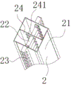
Fig. 4 is registration mast inner structure schematic diagram.
Fig. 5 is the structural representation of strut bar.
Fig. 6 is the structural representation of registration mast and lifting mechanism junction.
Fig. 7 is the partial enlarged drawing in Fig. 6.
Fig. 8 is the structural representation of removing the first panel of outside steel plate.
The specific embodiment
Below in conjunction with accompanying drawing and the specific embodiment, the utility model is described in further detail: referring to Fig. 1 to Fig. 8, a kind of offshore platform lifting mechanism, described lifting mechanism 3 is arranged on barge 1, on described barge 1, be provided with four the first through holes 11, described in each, the first through hole 11 tops are provided with described lifting mechanism 3, registration mast 2 is located in described lifting mechanism 3 and described the first through hole 11, described lifting mechanism 3 comprises two the first panels 31, between two the first panels 31, by eight the first hydraulic actuating cylinders 32, link together, described the first hydraulic actuating cylinder 32 is all vertical with two described the first panels 31 arbitrarily, described the first hydraulic actuating cylinder 32 two ends are rotatably connected to the first fixed block 37, described the first fixed block 37 is fixed on described the first panel 31, described the first hydraulic actuating cylinder 32 two ends are mutually vertical with the direction that the first fixed block 37 is rotationally connected, on two described the first panels 31, be all provided with for the second through hole 33 through registration mast 2, described the second through hole 33 both sides are provided with bracing frame 34, support frame as described above 34 is fixed on described the first panel 31, support frame as described above 34 is hinged with block teeth 35, described block teeth 35 are bending-like, on described block teeth 35, be hinged with the second hydraulic actuating cylinder 36, described the second hydraulic actuating cylinder 36 is hinged on described the first panel 31.Support frame as described above 34 is identical with the hinged direction of block teeth 35, block teeth 35 and the second hydraulic actuating cylinder 36, the second hydraulic actuating cylinder 36 and the first panel 31.In order to alleviate total quality and the installation that facilitates the first hydraulic actuating cylinder 32, the second hydraulic actuating cylinder 36 and bracing frame 34, described the first panel 31 is the outside frame-type steel plate structure that is coated with steel plate.
Described registration mast 2 is arranged on described barge 1 through described the first through hole 11 and the second through hole 33, in order to alleviate quality, described registration mast 2 comprises a pillar steel structure framework 21, in described framework 21, be provided with some strut bars 22, described some strut bars 22 comprise pressure-bearing post 221, described pressure-bearing post 221 two ends be provided with for increase and described framework 21 between the second panel 222 of contact surface, between described pressure-bearing post 221 and described the second panel 222, be provided with some reinforced ribs 223, for convenient location when the interior installation strut bar 22 of framework 21, in described framework 21, be also provided with the 3rd panel 24, on described the 3rd panel 24, be provided with some third through-holes 241, described strut bar 22 is located in described third through-hole 241, on relative two lateral surfaces of described framework 21, be provided with tooth bar 23, described block teeth 35 coordinate described registration mast 2 are fixed on described barge 1 with described tooth bar 23, described framework 21 seabed interaction places, bottom are provided with hemispherical projections 25, described hemispherical projections 25 sides extend some fins 26, arrange and when hemispherical projections 25 and fin 26 make registration mast 2 seabed interaction, easily stretch into seabed, and play directional tagging in the process stretching into seabed at registration mast 2.
Described the first hydraulic actuating cylinder 32 and the second hydraulic actuating cylinder 36 are all connected with oil pump and control setup.
This offshore platform dragged to desired location by ship before work, resistance while dragging in order to reduce barge 1, originally registration mast 2 is positioned at and is not stretched into the water surface topmost by block teeth 35 clampings, after arriving desired location, the second hydraulic actuating cylinder 36 of top shrinks and makes the block teeth 35 of top unclamp tooth bar 23, then the first hydraulic actuating cylinder 32 extends, the second hydraulic actuating cylinder 36 of top extends the block teeth 35 clamping tooth bars 23 that make top, then the second hydraulic actuating cylinder 36 of below shrinks and makes the block teeth 35 of below unclamp tooth bar 32, then the first hydraulic actuating cylinder 32 shrinks, the relative barge 1 of registration mast 2 is moved downward, then the second hydraulic actuating cylinder 36 of below extends, make the block teeth 35 of below block tooth bar 23, repeat so operation, until registration mast 2 stretches into seabed, again barge 1 plane is carried away to the water surface afterwards.When platform need to be shifted to other places, adopt contrary operation that registration mast 2 is extracted and promoted from seabed.

Claims (3)

1. an offshore platform lifting mechanism, it is characterized in that: described lifting mechanism (3) comprises two the first panels (31), between two the first panels (31), by some the first hydraulic actuating cylinders (32), link together, described the first hydraulic actuating cylinder (32) is all vertical with two described the first panels (31) arbitrarily, on two described the first panels (31), be all provided with for the second through hole (33) through registration mast (2), described the second through hole (33) both sides are provided with bracing frame (34), support frame as described above (34) is fixed on described the first panel (31), support frame as described above (34) is hinged with block teeth (35), described block teeth (35) are bending-like, on described block teeth (35), be hinged with the second hydraulic actuating cylinder (36), described the second hydraulic actuating cylinder (36) is hinged on described the first panel (31), support frame as described above (34) and block teeth (35), block teeth (35) and the second hydraulic actuating cylinder (36), the second hydraulic actuating cylinder (36) is identical with the hinged direction of the first panel (31).
2. a kind of offshore platform lifting mechanism as claimed in claim 1, is characterized in that: described the first panel (31) is the outside frame-type steel plate structure that is coated with steel plate.
3. a kind of offshore platform lifting mechanism as claimed in claim 1, it is characterized in that: described the first hydraulic actuating cylinder (32) two ends are rotatably connected to the first fixed block (37), it is upper that described the first fixed block (37) is fixed on described the first panel (31), and described the first hydraulic actuating cylinder (32) two ends are mutually vertical with the direction that described the first fixed block (37) is rotationally connected.
CN201320476505.6U 2013-08-06 2013-08-06 Offshore platform lifting mechanism Expired - Fee Related CN203473198U (en)

Priority Applications (1)

Application Number Priority Date Filing Date Title
CN201320476505.6U CN203473198U (en) 2013-08-06 2013-08-06 Offshore platform lifting mechanism

Applications Claiming Priority (1)

Application Number Priority Date Filing Date Title
CN201320476505.6U CN203473198U (en) 2013-08-06 2013-08-06 Offshore platform lifting mechanism

Publications (1)

Publication Number Publication Date
CN203473198U true CN203473198U (en) 2014-03-12

Family

ID=50221580

Family Applications (1)

Application Number Title Priority Date Filing Date
CN201320476505.6U Expired - Fee Related CN203473198U (en) 2013-08-06 2013-08-06 Offshore platform lifting mechanism

Country Status (1)

Country Link
CN (1) CN203473198U (en)

Similar Documents

Publication Publication Date Title
CN107542101B (en) Construction method of offshore four-buoy-buoyancy tank combined foundation structure
CN201695381U (en) Three-cylindrical foundation one-legged mooring platform
CN111469992A (en) Floating offshore wind power structure foundation with damping effect and stability control method
EP3464733B1 (en) A seabed supported unit and method to provide a shallow water drilling terminal
CN112127384A (en) Suspended Ballast Offshore Wind Turbine Floating Infrastructure
CN102328732A (en) Offshore pile driving, pile pressing and installing united engineering ship
CN207089600U (en) Can be from the tension leg type offshore floating wind turbine foundation of floating installation
CN102285429A (en) Floating type supporting structure for marine windmill
CN104727336A (en) Construction method of large single-pipe pile foundation of shallow-sea wind power plant
CN212243735U (en) Floating type offshore wind power structure foundation with damping effect
CN104234069A (en) Offshore wind turbine foundation with plug-in honeycomb structure chassis
CN114855865A (en) Tensioning type fan foundation anchored on rock-based seabed and arrangement method
CN102409650A (en) Installation method of shallow water ocean jacket platform
CN203939028U (en) Portable marine piling position-limited rack
CN202298591U (en) Shallow water tremie frame platform
CN200971492Y (en) Pile submarine drilling basal disc with suction
CN202023182U (en) Waterborne drilling foam platform
CN103397623B (en) A kind of offshore platform
HK1213532A1 (en) A specified lifting and piling barge for cellular arc cell construction
CN103482036A (en) Buoyancy tower type ocean platform
CN102923261A (en) A bottom-mounted offshore wind turbine installation barge
CN203440803U (en) Offshore platform
CN203782670U (en) Floating box platform for over-water construction
CN203486110U (en) Buoyant-tower-type ocean platform
CN115258092A (en) Integral installation method of floating type water photovoltaic

Legal Events

Date Code Title Description
GR01 Patent grant
GR01 Patent grant
C56 Change in the name or address of the patentee

Owner name: JESSN OCEAN EQUIPMENT CO., LTD.

Free format text: FORMER NAME: JESSN OCEAN EQUIPMENT LTD.

Owner name: JESSN OCEAN EQUIPMENT LTD.

Free format text: FORMER NAME: NINGBO GESSN OCEAN EXPLOITATION CO., LTD.

CP01 Change in the name or title of a patent holder

Address after: 315806 No. 206 Tiantai Mountain Road, Beilun District, Zhejiang, Ningbo

Patentee after: JESSN MARINE EQUIPMENT Co.,Ltd.

Address before: 315806 No. 206 Tiantai Mountain Road, Beilun District, Zhejiang, Ningbo

Patentee before: Victory Marine Equipment Co.,Ltd.

Address after: 315806 No. 206 Tiantai Mountain Road, Beilun District, Zhejiang, Ningbo

Patentee after: Victory Marine Equipment Co.,Ltd.

Address before: 315806 No. 206 Tiantai Mountain Road, Beilun District, Zhejiang, Ningbo

Patentee before: NINGBO JESSN OCEAN DEVELOPMENT Co.,Ltd.

CF01 Termination of patent right due to non-payment of annual fee

Granted publication date: 20140312