CN2042811U - Waste gas braking device of internal-combustion engine - Google Patents
Waste gas braking device of internal-combustion engine Download PDFInfo
- Publication number
- CN2042811U CN2042811U CN 89210776 CN89210776U CN2042811U CN 2042811 U CN2042811 U CN 2042811U CN 89210776 CN89210776 CN 89210776 CN 89210776 U CN89210776 U CN 89210776U CN 2042811 U CN2042811 U CN 2042811U
- Authority
- CN
- China
- Prior art keywords
- combustion engine
- internal
- waste gas
- braking device
- gas braking
- Prior art date
- Legal status (The legal status is an assumption and is not a legal conclusion. Google has not performed a legal analysis and makes no representation as to the accuracy of the status listed.)
- Expired - Lifetime
Links
- 239000002912 waste gas Substances 0.000 title claims abstract description 8
- 238000002485 combustion reaction Methods 0.000 title abstract description 12
- 239000007789 gas Substances 0.000 claims abstract description 9
- 206010020852 Hypertonia Diseases 0.000 claims description 2
- 238000012423 maintenance Methods 0.000 abstract description 5
- 230000007547 defect Effects 0.000 abstract 1
- 230000004913 activation Effects 0.000 description 1
Images
Landscapes
- Braking Arrangements (AREA)
Abstract
The utility model discloses the waste gas braking device of an internal-combustion engine, overcoming the defects of consumption of the effective power of the internal-combustion engine, complicated structure, high cost, complicated maintenance, etc. Of an original gas braking system. After various wheel-type tractors, trailer machine groups or motor cars adopt the waste gas braking device of an internal-combustion engine, the effective power of the internal-combustion engine is not consumed. The waste gas braking device of an internal-combustion engine has the advantages of simple structure, low cost, and convenient maintenance.
Description
The utility model relates to a kind of engine exhaust gas brake equipment.
By wheel-tire tractor and trailer unit or the automobile of combustion engine, all adopt the gas braking system that forms by air pump, air receiver, brake activation valve, steering unit and compressed air brake cylinder before as the various models of power.Because this system makes combustion engine consume certain effective power by the power running of combustion engine.This in addition gas braking system architecture complexity, the cost height, maintenance is inconvenient.
To be that design is a kind of do not consume that the combustion engine effective power is simple in structure, cost is low, engine exhaust gas brake equipment easy to maintenance to the purpose of this utility model.
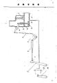
The utility model is achieved in that the engine exhaust gas brake equipment, it is characterized in that: valve 5 is closed exhausr port by the four-bar linkage up-and-down movement; Waste gas by manage 7 and pipe 6 enter compressed air brake cylinder 13 and promote 14 swings of brake shoe expander rocking arms; When in the pipeline during hypertonia, check valve 1 is opened.
But the spring bar 10 in the four-bar linkage is elastic telescopics.
The utility model is compared with existing gas braking system, and advantage is the effective power that does not consume combustion engine, and is simple in structure, and cost is low, and is easy to maintenance.
The utility model is described further with embodiment below in conjunction with accompanying drawing:
In the accompanying drawing:
1 check valve, 12,9,8,2 four-bar linkages, 10 spring bars, 5 valves, 4 valve springs, 6,7 pipes, 13 compressed air brake cylinders, 14 brake shoe expander rocking arms.
When the wheel-tire tractor of various models and trailer unit or automobile brake, the driver closes by the valve 5 that the control four-bar linkage will be contained on the I. C. engine exhaust menifold, whole pipeline inner pressure is raise, waste gas enters compressed air brake cylinder 13 through managing 6,7, promote brake shoe expander rocking arm 14 swings on the wheel, to reach the brake purpose.Check valve 1 is opened when pipeline inner pressure is too high.
Claims (2)
1, engine exhaust gas brake equipment is characterized in that: valve 5 is closed exhausr port by the four-bar linkage up-and-down movement; Waste gas by manage 7 and pipe 6 enter compressed air brake cylinder 13 and promote 14 swings of brake shoe expander rocking arms; When in the pipeline during hypertonia, check valve 1 is opened.
2, engine exhaust gas brake equipment according to claim 1 is characterized in that: but the spring bar 10 in the four-bar linkage is elastic telescopics.
Priority Applications (1)
| Application Number | Priority Date | Filing Date | Title |
|---|---|---|---|
| CN 89210776 CN2042811U (en) | 1989-01-31 | 1989-01-31 | Waste gas braking device of internal-combustion engine |
Applications Claiming Priority (1)
| Application Number | Priority Date | Filing Date | Title |
|---|---|---|---|
| CN 89210776 CN2042811U (en) | 1989-01-31 | 1989-01-31 | Waste gas braking device of internal-combustion engine |
Publications (1)
| Publication Number | Publication Date |
|---|---|
| CN2042811U true CN2042811U (en) | 1989-08-16 |
Family
ID=4867117
Family Applications (1)
| Application Number | Title | Priority Date | Filing Date |
|---|---|---|---|
| CN 89210776 Expired - Lifetime CN2042811U (en) | 1989-01-31 | 1989-01-31 | Waste gas braking device of internal-combustion engine |
Country Status (1)
| Country | Link |
|---|---|
| CN (1) | CN2042811U (en) |
Cited By (1)
| Publication number | Priority date | Publication date | Assignee | Title |
|---|---|---|---|---|
| CN100535416C (en) * | 2003-12-16 | 2009-09-02 | 嘉娜拉企业有限公司 | Apparatus and method for pressure relief in an exhaust brake |
-
1989
- 1989-01-31 CN CN 89210776 patent/CN2042811U/en not_active Expired - Lifetime
Cited By (1)
| Publication number | Priority date | Publication date | Assignee | Title |
|---|---|---|---|---|
| CN100535416C (en) * | 2003-12-16 | 2009-09-02 | 嘉娜拉企业有限公司 | Apparatus and method for pressure relief in an exhaust brake |
Similar Documents
| Publication | Publication Date | Title |
|---|---|---|
| CN206664518U (en) | A kind of anticollision auxiliary brake | |
| CN2042811U (en) | Waste gas braking device of internal-combustion engine | |
| CN101172462A (en) | Inflating vibration damping system of vehicle | |
| CN2465974Y (en) | Sedan driven by compressed air | |
| CN2379345Y (en) | Booster for vehicle wheel | |
| CN2138599Y (en) | Brake inflating device for wheeled tractor | |
| CN2813389Y (en) | Electric compression pump energy-saving device | |
| CN201095320Y (en) | Gravity automatic inflating device | |
| CN2260016Y (en) | Tyre inflating self-service device for vehicles with no air pump | |
| CN2419083Y (en) | High pressure pneumatic vehical driving device | |
| CN201077362Y (en) | Kinetic energy conversion device of electric vehicle | |
| CN201573640U (en) | Braking control valve for composite braking of motor vehicles | |
| CN2473002Y (en) | Vehicle carried air inflating machine for dismantling tyre | |
| CN2686952Y (en) | Brake antiskid device of motor vehicle for ice-snow road | |
| CN201109422Y (en) | Automobile wheel rotating suction energy-saving apparatus | |
| CN2236020Y (en) | Accelerating regulation-control device for IC engine of motor vehicle | |
| CN2450037Y (en) | Lifting device for motor vehicle | |
| CN2263607Y (en) | Controllor special for | |
| CN2241230Y (en) | Exhaust control valve for internal combustion engine | |
| CN2281455Y (en) | Tyre air valve of hand-push tractor | |
| CN200942757Y (en) | Automobile emergency braking system | |
| CN2764682Y (en) | Sedan braking system | |
| CN2601906Y (en) | Exhaust brake valve | |
| CN2223709Y (en) | Braking device with automatic force-aid for motor vehicle | |
| CN2197269Y (en) | Secondary brake for vehicles |
Legal Events
| Date | Code | Title | Description |
|---|---|---|---|
| C06 | Publication | ||
| PB01 | Publication | ||
| C14 | Grant of patent or utility model | ||
| GR01 | Patent grant | ||
| C17 | Cessation of patent right | ||
| CX01 | Expiry of patent term |