CN212820093U - Sand mill for PU (polyurethane) coating - Google Patents
Sand mill for PU (polyurethane) coating Download PDFInfo
- Publication number
- CN212820093U CN212820093U CN202021531957.6U CN202021531957U CN212820093U CN 212820093 U CN212820093 U CN 212820093U CN 202021531957 U CN202021531957 U CN 202021531957U CN 212820093 U CN212820093 U CN 212820093U
- Authority
- CN
- China
- Prior art keywords
- jar body
- sanding
- wall
- coating
- workbin
- Prior art date
- Legal status (The legal status is an assumption and is not a legal conclusion. Google has not performed a legal analysis and makes no representation as to the accuracy of the status listed.)
- Active
Links
- 238000000576 coating method Methods 0.000 title claims abstract description 27
- 239000011248 coating agent Substances 0.000 title claims abstract description 25
- 239000004576 sand Substances 0.000 title claims abstract description 24
- 239000004814 polyurethane Substances 0.000 title description 24
- 229920002635 polyurethane Polymers 0.000 title description 2
- 239000000463 material Substances 0.000 claims description 22
- 230000000903 blocking effect Effects 0.000 claims description 10
- 239000003973 paint Substances 0.000 claims description 10
- 238000000227 grinding Methods 0.000 claims description 8
- 235000020004 porter Nutrition 0.000 claims description 8
- 230000011218 segmentation Effects 0.000 claims 1
- 239000002994 raw material Substances 0.000 abstract description 13
- 238000012216 screening Methods 0.000 abstract description 6
- 238000004519 manufacturing process Methods 0.000 abstract description 3
- 238000002360 preparation method Methods 0.000 abstract description 3
- 238000009826 distribution Methods 0.000 description 4
- 238000007670 refining Methods 0.000 description 3
- 238000010586 diagram Methods 0.000 description 2
- 210000005056 cell body Anatomy 0.000 description 1
- 238000005516 engineering process Methods 0.000 description 1
- 238000010030 laminating Methods 0.000 description 1
- 238000000034 method Methods 0.000 description 1
- 239000011527 polyurethane coating Substances 0.000 description 1
- 239000007921 spray Substances 0.000 description 1
- 238000005507 spraying Methods 0.000 description 1
- 239000004753 textile Substances 0.000 description 1
Images



Landscapes
- Crushing And Grinding (AREA)
Abstract
The utility model discloses a sand mill for PU coating relates to PU coating production field, does not set up screening plant to the sand mill that current PU coating preparation was used when the ejection of compact to the product granularity difference that leads to after the sanding is great, leads to the problem of PU coating performance reduction, proposes following scheme now, and it is including a jar body and workbin, the jar body is the slope setting, just the bottom fixed mounting of the jar body has the landing leg, the top fixed mounting of the jar body has the workbin, just the jar internal chamber switches on with workbin inner chamber, the one end that the workbin was kept away from to the jar body is provided with the opening, the jar body is kept away from open-ended one end fixed mounting and is had driving motor. The utility model discloses novel structure, and the device not only can carry out the sanding to the raw materials of PU coating and handle, can sieve it simultaneously and handle, can make the sieve vibrations moreover, prevent that the sieve from blockking up, guarantee its normal screening efficiency.
Description
Technical Field
The utility model relates to a PU coating production field especially relates to a sand mill for PU coating.
Background
The PU paint is a general name of all polyurethane coatings, and the film forming mode of the PU paint is natural film forming without special processes. The PU coating has good comprehensive performance; the paint has good hardness, fullness, adhesion, durability and hand feeling, and the paint film is thin and not very hard; but the adhesion is particularly good; the PU paint has uniform gloss and is not very bright in appearance, the textile and color of the floor can be well displayed, and the PU paint is generally used by industry and buildings, so that the technology is mature, the color system is more, and the spraying requirement is easily met. However, the requirement for paint spray booth and baking booth is high because of the harm to human body, and at the same time, human body protection measures are needed.
PU coating need use the sand mill to carry out the refining of certain degree to its raw materials when production preparation, and current PU coating is when using the sand mill to carry out the sanding operation, because it does not set up screening plant in ejection of compact position to it is great to lead to the product granularity difference after the sanding, leads to PU coating performance to reduce, consequently, in order to solve this type of problem, we have proposed a sand mill for PU coating.
SUMMERY OF THE UTILITY MODEL
The utility model provides a sand mill for PU coating has solved the sand mill that current PU coating preparation was used and has not set up screening plant when the ejection of compact to the product granularity difference that leads to after the sanding is great, leads to the problem of PU coating performance reduction.
In order to achieve the above purpose, the utility model adopts the following technical scheme:
a sand mill for PU coating comprises a tank body and a material box, wherein the tank body is arranged obliquely, a supporting leg is fixedly arranged at the bottom end of the tank body, the material box is fixedly arranged at the top end of the tank body, the inner cavity of the tank body is communicated with the inner cavity of the material box, an opening is formed in one end, away from the material box, of the tank body, a driving motor is fixedly arranged at one end, away from the opening, of the tank body, the end part of an output shaft of the driving motor extends to the inside of the tank body and is fixedly provided with a feeding rod, a material blocking device is arranged on the feeding rod, a sand grinding block is fixedly sleeved on the circumferential side wall of the feeding rod, a fixed block is fixedly arranged on the inner wall of the tank body, the end part of the feeding rod penetrates through the fixed block and is connected with a main gear plate, the sand grinding blocks are arranged in, the inside slidable mounting of the jar body has detachable sieve, just the internally mounted of the jar body has with main gear dish complex vibrator for prevent that the sieve from blockking up.
Preferably, the material blocking device comprises a connecting rod and a material blocking plate, the two connecting rods with the same structure are fixedly connected to the circumferential side wall of the feeding rod, and the material blocking plate is fixedly connected to the end part of each connecting rod.
Preferably, the cross section of the striker plate is semicircular, and the striker plate is attached to the inner wall of the tank body.
Through adopting above-mentioned technical scheme, the striker plate can intermittent type nature open and close the material mouth between jar body and the workbin to make the inside raw materials of workbin orderly enter into jar internal portion, prevent that jar internal portion raw materials from piling up.
Preferably, the outer wall of the sand grinding block and the inner wall of the sand grinding groove are both provided with sand grinding balls.
By adopting the technical scheme, the size of the sand grinding ball is changed according to levels, so that the raw materials can be refined step by step.
Preferably, the vibrator includes driven lever, pinion disc and cam, the inner wall of the jar body rotates and installs two driven levers that the structure is the same, just the tip fixedly connected with pinion disc of driven lever, pinion disc and the meshing of master gear dish, just the circumference lateral wall of driven lever is fixed to be cup jointed the cam.
Preferably, one side of the sieve plate, which is close to the main gear plate, is provided with a contact groove body matched with the cam.
Preferably, the inner wall of the jar body is provided with two spacing grooves that are the symmetric distribution along its length direction, two stoppers that are the symmetric distribution of circumference lateral wall fixedly connected with of sieve, just stopper slidable mounting is in the spacing inslot portion, just be connected with reset spring between the inner wall of spacing groove and the stopper.
Through adopting above-mentioned technical scheme, drive pinion disc and driven lever and cam through master gear dish and rotate, rethread cam and sieve contact make its and the inside reset spring cooperation of spacing inslot, can make sieve reciprocating motion, produce vibrations, avoid the sieve to block up.
The utility model has the advantages that:
1. drive porter bar and connecting rod and striker plate through driving motor and rotate for the inside raw materials of workbin can intermittent type nature enter into jar internal portion, and carry out steady pay-off through the porter bar, then can carry out effectual sanding to the raw materials of PU coating and refine the processing through the cooperation of the sanding ball on sanding block and the fixed block.
2. Can effectually sieve the PU coating raw materials after the sanding to drive the master gear dish through the porter bar and rotate, make it drive pinion dish and cam rotation, rethread reset spring's cooperation can guarantee that the internal reciprocating motion of jar again of sieve produces vibrations, thereby can prevent effectively that the sieve from blockking up, guarantees the normal screening efficiency of sieve.
To sum up, the device not only can carry out the sanding to the raw materials of PU coating and handle, can sieve it simultaneously and handle, can make the sieve vibrations moreover, prevents that the sieve from blockking up, guarantees its normal screening efficiency.
Drawings
Fig. 1 is a schematic structural diagram of the present invention.
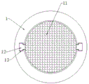
Fig. 2 is a schematic cross-sectional view taken along line a-a of fig. 1 according to the present invention.
Fig. 3 is an enlarged schematic structural diagram of B in fig. 1 according to the present invention.
Fig. 4 is a cross-sectional view of the striker plate of the present invention.
Reference numbers in the figures: 1. a tank body; 2. a material box; 3. a drive motor; 4. a striker plate; 5. a connecting rod; 6. a feed bar; 7. a support leg; 8. sanding blocks; 9. a fixed block; 10. a main gear plate; 11. a sieve plate; 12. a limiting block; 13. a limiting groove; 14. a driven lever; 15. a cam; 16. A pinion gear plate; 17. contacting the tank body.
Detailed Description
The technical solutions in the embodiments of the present invention will be described clearly and completely with reference to the accompanying drawings in the embodiments of the present invention, and it is obvious that the described embodiments are only some embodiments of the present invention, not all embodiments.
Referring to fig. 1-4, a sand mill for PU coating, includes a tank body 1 and a bin 2, the tank body 1 is arranged obliquely, and the bottom fixed mounting of the tank body 1 has a leg 7, the top fixed mounting of the tank body 1 has the bin 2, and the tank body 1 has an inner chamber communicated with the bin 2, one end of the tank body 1 away from the bin 2 is provided with an opening, one end of the tank body 1 away from the opening is fixedly mounted with a driving motor 3, and the output shaft end of the driving motor 3 extends to the inside of the tank body 1 and is fixedly mounted with a feeding rod 6, the feeding rod 6 is mounted with a material blocking device, and the circumferential side wall of the feeding rod 6 is fixedly sleeved with a sand grinding block 8, the inner wall of the tank body 1 is fixedly mounted with a fixed block 9, and the end of the feeding rod 6 penetrates through the fixed block 9 and is connected with a main gear disc 10, and all are round platform form, be provided with the sanding groove on the fixed block 9, and the sanding groove matches with sanding block 8, the inside slidable mounting of jar body 1 has detachable sieve 11, just the internally mounted of jar body 1 has the vibrator with master gear dish 10 complex, is used for preventing sieve 11 jam, striker includes connecting rod 5 and striker plate 4, just the circumference lateral wall fixedly connected with two connecting rods 5 that the structure is the same of porter 6, just the tip fixedly connected with striker plate 4 of connecting rod 5, the cross-section of striker plate 4 is half circular ring form, just striker plate 4 and the laminating of jar body 1 inner wall, sanding ball is all installed to the outer wall of sanding block 8 and the inner wall of sanding groove, vibrator includes driven lever 14, pinion disc 16 and cam 15, the inner wall of jar body 1 rotates and installs two driven levers 14 that the structure is the same, just the tip fixedly connected with pinion disc 16 of driven lever 14, pinion disc 16 and the meshing of main gear dish 10, just cam 15 has been cup jointed to the circumference lateral wall of driven lever 14 fixed, one side that sieve 11 is close to main gear dish 10 is equipped with the contact cell body 17 that matches with cam 15, the inner wall of jar body 1 is provided with two spacing grooves 13 that are the symmetric distribution along its length direction, two stopper 12 that are the symmetric distribution of circumference lateral wall fixedly connected with of sieve 11, just stopper 12 slidable mounting is inside spacing groove 13, just be connected with reset spring between the inner wall of spacing groove 13 and stopper 12.
The working principle is as follows: when the device is used, the raw materials of PU coating are placed in the material box 2, and the material blocking plate 4 is guaranteed to block a material opening between the tank body 1 and the material box 2 at the moment, then the driving motor 3 is started, the driving motor 3 drives the feeding rod 6 to rotate, the feeding rod 6 drives the connecting rod 5 and the material blocking plate 4 to rotate, so that the material opening between the tank body 1 and the material box 2 is opened, the raw materials enter the tank body 1 and are conveyed through the feeding rod 6, the feeding rod 6 drives the sanding block 8 to rotate, sanding balls between the sanding block 8 and the fixing block 9 can perform sanding refining treatment on the raw materials, the raw materials after sanding refining are discharged through the material opening in the fixing block 9, and are screened through the sieve plate 11;
when the feeding rod 6 rotates, the feeding rod 6 drives the main gear disc 10 to rotate, the main gear disc 10 drives the auxiliary gear disc 16 to rotate, so that the auxiliary gear disc 16 drives the driven rod 14 and the cam 15 to rotate, when the cam 15 contacts with the contact groove body 17 on the screen plate 11, the screen plate 11 is pushed to slide in the tank body 1, the limiting block 12 is driven to slide in the limiting groove 13, the reset spring in the limiting groove 13 is stretched, when the driven rod 14 continues to drive the cam 15 to rotate, the cam 15 is separated from the contact groove body 17 on the screen plate 11, at the moment, the limiting block 12 is pulled by the tension of the reset spring to reversely slide in the limiting groove 13 and drive the screen plate 11 to reversely slide until the cam 15 contacts with the contact groove body 17 on the screen plate 11 again, the operation is repeated, and therefore, the screen plate 11 can repeatedly move in the tank body 1, vibration is generated so that the screen plate 11 can be effectively prevented from being clogged.
The above, only be the concrete implementation of the preferred embodiment of the present invention, but the protection scope of the present invention is not limited thereto, and any person skilled in the art is in the technical scope of the present invention, according to the technical solution of the present invention and the utility model, the concept of which is equivalent to replace or change, should be covered within the protection scope of the present invention.
Claims (7)
1. The utility model provides a sand mill for PU coating, includes a jar body (1) and workbin (2), its characterized in that, jar body (1) is the slope setting, just the bottom fixed mounting of jar body (1) has landing leg (7), the top fixed mounting of jar body (1) has workbin (2), just jar body (1) inner chamber switches on with workbin (2) inner chamber, the one end that workbin (2) were kept away from to jar body (1) is provided with the opening, jar body (1) is kept away from open-ended one end fixed mounting and is had driving motor (3), just the output shaft tip of driving motor (3) extends to jar body (1) inside fixed mounting and has porter bar (6), install stock stop on porter bar (6), just the fixed cover of circumference lateral wall of porter bar (6) is equipped with sand grinding block (8), the inner wall fixed mounting of jar body (1) has fixed block (9), just the tip of porter bar (6) runs through fixed block (9), and is connected with master gear dish (10), sanding block (8) are two segmentation settings, and all are the round platform form, be provided with the sanding groove on fixed block (9), and sanding groove and sanding block (8) match, the inside slidable mounting of the jar body (1) has detachable sieve (11), just the internally mounted of the jar body (1) has and master gear dish (10) complex vibrator for prevent that sieve (11) from blockking up.
2. The sand mill for PU paint according to claim 1, wherein the material blocking device comprises a connecting rod (5) and a material blocking plate (4), two connecting rods (5) with the same structure are fixedly connected to the circumferential side wall of the feeding rod (6), and the material blocking plate (4) is fixedly connected to the end of the connecting rods (5).
3. The sand mill for PU paint according to claim 2, wherein the cross section of the striker plate (4) is semicircular, and the striker plate (4) is attached to the inner wall of the tank body (1).
4. A sanding machine for PU coatings according to claim 1 characterized in that the sanding balls are installed on both the outer wall of the sanding block (8) and the inner wall of the sanding tank.
5. A sanding machine for PU coatings according to claim 1, characterized in that said vibrating device comprises a driven rod (14), a pinion disk (16) and a cam (15), two driven rods (14) with the same structure are rotatably installed on the inner wall of the tank body (1), the end of the driven rod (14) is fixedly connected with the pinion disk (16), the pinion disk (16) is engaged with the driving disk (10), and the cam (15) is fixedly sleeved on the circumferential side wall of the driven rod (14).
6. A sander for PU paint according to claim 1, characterized in that the side of the screen plate (11) near the main gear plate (10) is provided with a contact groove (17) matching with the cam (15).
7. The sand mill for PU coating according to claim 1, wherein the inner wall of the tank body (1) is provided with two symmetrically distributed limiting grooves (13) along the length direction thereof, the circumferential side wall of the screen plate (11) is fixedly connected with two symmetrically distributed limiting blocks (12), the limiting blocks (12) are slidably mounted inside the limiting grooves (13), and a return spring is connected between the inner wall of the limiting grooves (13) and the limiting blocks (12).
Priority Applications (1)
| Application Number | Priority Date | Filing Date | Title |
|---|---|---|---|
| CN202021531957.6U CN212820093U (en) | 2020-07-29 | 2020-07-29 | Sand mill for PU (polyurethane) coating |
Applications Claiming Priority (1)
| Application Number | Priority Date | Filing Date | Title |
|---|---|---|---|
| CN202021531957.6U CN212820093U (en) | 2020-07-29 | 2020-07-29 | Sand mill for PU (polyurethane) coating |
Publications (1)
| Publication Number | Publication Date |
|---|---|
| CN212820093U true CN212820093U (en) | 2021-03-30 |
Family
ID=75124715
Family Applications (1)
| Application Number | Title | Priority Date | Filing Date |
|---|---|---|---|
| CN202021531957.6U Active CN212820093U (en) | 2020-07-29 | 2020-07-29 | Sand mill for PU (polyurethane) coating |
Country Status (1)
| Country | Link |
|---|---|
| CN (1) | CN212820093U (en) |
-
2020
- 2020-07-29 CN CN202021531957.6U patent/CN212820093U/en active Active
Similar Documents
| Publication | Publication Date | Title |
|---|---|---|
| CN109092533A (en) | A kind of rubber production processing pulverizer | |
| KR20160087085A (en) | Seeds separation unit | |
| CN212820093U (en) | Sand mill for PU (polyurethane) coating | |
| CN106235355A (en) | A kind of Radix Ipomoeae device for peeling | |
| CN205052737U (en) | Machine is kneaded to tealeaves that noise is little | |
| CN102342571A (en) | Dehulling machine for tuberous and root-typed crops | |
| CN207953526U (en) | A kind of grinding device of hot investment casting high-strength wear-resistant alloy bucket tooth toothholder | |
| CN211359109U (en) | Quick milling equipment for building material | |
| CN201718429U (en) | Tuber and tuberous root crops peeling machine | |
| CN208727370U (en) | A kind of aqueous efficient material mixer of the ship coating production with secondary equipment | |
| CN208323043U (en) | A kind of button polishing machine | |
| CN203618705U (en) | Continuous tea twisting machine | |
| CN119237075B (en) | Ball mill for vibrating screen type broken tungsten carbide powder | |
| CN206651348U (en) | A kind of gingko peeling machine | |
| CN207767654U (en) | Automatic roughing machine for shoe soles | |
| CN221016259U (en) | Essence grinder | |
| CN202129713U (en) | Hard capsule rejecting polisher | |
| US2575007A (en) | Machine for painting the interior of pipe bowls | |
| CN215695614U (en) | Liquid medicine purification device | |
| CN216538863U (en) | Raw material grinding machine for cream production | |
| CN114904617A (en) | Broken grinding device of medicinal material | |
| CN211812420U (en) | Feed processing charging bucket discharge apparatus | |
| CN211983678U (en) | Automatic peeling device for nut production | |
| CN210790596U (en) | Frosted device for frosted glass cup | |
| CN202566216U (en) | Walnut peel peeling and washing machine |
Legal Events
| Date | Code | Title | Description |
|---|---|---|---|
| GR01 | Patent grant | ||
| GR01 | Patent grant |