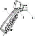
Back row backrest movement gap shielding curtain
Technical Field
The utility model relates to an automotive interior field, concretely relates to back row back movement clearance shielding curtain.
Background
With the continuous improvement of the requirements of the end users on the riding comfort of the rear seats, the requirements of the functional configuration of the rear seats are gradually increased; the back of the present automobile back row seat can be adjusted front and back, and the back row seat is adjusted for the automobile body wrapping frame, so that a large gap is left between the back row seat and the wrapping frame, the framework of the seat is exposed outside and is not attractive, the overall appearance quality of the automobile is affected, and the automobile back row seat is not well cleaned after ash falls due to the fact that the large gap is left between the back row seat and the wrapping frame.
SUMMERY OF THE UTILITY MODEL
An object of the utility model is to provide an in the back row back of the seat adjusts the motion process, make the back row back and the automobile body parcel clearance between the frame shield the shielding curtain.
In order to achieve the above object, the utility model provides a following technical scheme:
a back row backrest movement gap shielding curtain comprises a shielding bracket and a return torsional spring which are integrally injection-molded, wherein the shielding bracket is integrally n-shaped and comprises a first rotating frame, a second rotating frame, a bracket, a fixing groove and a clamping part, the bracket is n-shaped, the rear side of the bracket is integrally connected with the clamping part which is n-shaped, the rear sides at the two ends of the clamping part are integrally connected with the fixing groove extending towards the bracket, the bottom of the fixing groove at one end is integrally connected with the first rotating frame, the fixing groove at the other end is integrally connected with the second rotating frame through a connecting part, the connecting part is integrally connected onto the inner wall corresponding to the bracket, the top of the second rotating frame is integrally connected with the bottom of the corresponding end of the bracket, the bottoms of the first rotating frame and the second rotating frame are provided with bayonets, and the return torsional spring is arranged inside the fixing groove, the fixed end of the return torsion spring is clamped in the fixing groove, and the moving end of the return torsion spring is matched with the groove in the buckle.
A clamping groove is formed between the clamping portion and the support, and a plurality of clamping points are arranged on the side wall, away from one side of the support, of the clamping groove.
The utility model discloses a fixed slot, including fixed slot, separation blade, baffle piece, limiting hole, the both sides relative lateral wall of fixed slot inside all processes on all processing has the separation blade, makes the upper and lower both ends of separation blade all with form the gap between the lateral wall, the integrative separation blade turning that has in separation blade rear, the rear end of fixed slot is "worker" style of calligraphy, and the four corners of "worker" style of calligraphy all processes the limiting hole, the symmetry processing has the fender point on.
The support deviates from homogeneous connection and has a plurality of intercrossing's strengthening rib on the surface A of one side of joint portion, the surface A of support one side is like the inside slope of support, makes and forms acute angle alpha between the surface A of support and the Y axle.
All weak places of atress on sheltering from the support all are connected with the strengthening rib integratively.
The bracket is wrapped with a protective surface.
The utility model has the advantages and the beneficial effect
1. The utility model discloses a with the one end card of return torsional spring in the fixed slot, the other end passes through the buckle to be pressed on the support of skeleton and with the bayonet socket joint of swivel mount on the rotation axis of seat skeleton for this application is connected on back row seat back, guarantees to shelter from curtain and parcel shelf seamless when the back is adjusted.
2. The utility model discloses a bayonet socket joint of swivel mount makes shielding curtain cooperation skeleton rotation axis rotate on the rotation axis of seat skeleton, when satisfying the back and adjust forward or afterwards, and the shielding curtain can be adjusted along with the change of back angle, the regulation motion when satisfying back turned angle.
3. The utility model discloses a return torsional spring supports the shielding curtain support, supports through the return torsional spring in the inside slip of buckle recess, can realize that the back is when forward or backward rotation, and the shielding curtain can be adjusted along with the change of back angle, makes the clearance between shielding curtain and the automobile body parcel frame adjustable.
4. The utility model discloses an wholly be integrative injection moulding structure, the material is PP + glass fiber's plastics material, consequently can reach to subtract heavy and the effect of making an uproar of falling (NVH noise <45 dB).
5. The utility model discloses the peripheral homogeneous body that the support closes on backrest one side has the strengthening rib of intercrossing, the strengthening rib can improve shielding curtain transverse rigidity and intensity, prevents that the support atress from warping.
6. The utility model discloses a mask and back row seat's mask structure as an organic whole, need the cut-parts owing to the demand of shape at the junction that shelters from support and seat skeleton, made the seat skeleton and the mask that shelters from the support along with the shape and do not have the fold, one side mask that shelters from support and seat skeleton junction links to each other with the skeleton of seat through the mask fixed point, and the opposite side is sewed up with the card strip to insert in the draw-in groove in the joint portion behind the mask parcel that will sew up card strip one end after the support, carry on spacingly through the joint point pair card strip at last, sew up the mask that support and seat skeleton are connected at last, make this mask sew up the department and form an inside sunken crease, prevent like this when the shielding curtain expandes or fold that the mask curtain from upwards having bulged the formation fold with the mask of seat back junction.
7. The utility model discloses a with low costs, the overall quality is light, can make zero clearance fit between back row backrest and the parcel frame, can prevent that the dust from dropping in the gap between back row backrest and the parcel frame to the holistic appearance quality of car has been guaranteed.
Drawings
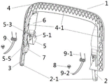
Fig. 1 is a schematic view of the overall structure of the present invention;
fig. 2 is an exploded view of the present invention;
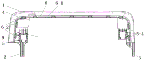
fig. 3 is a rear view of the present invention;
fig. 4 is a schematic view of another aspect of the present invention;
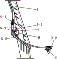
fig. 5 is a sectional view of the fixing groove and the return torsion spring of the present invention after being combined;
FIG. 6 is an enlarged view of the fixing groove and the return torsion spring of the present invention after being combined;
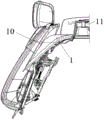
FIG. 7 is a schematic view of the forward and rearward extreme positions of the present invention after engagement with the seat back;
FIG. 8 is a schematic view of the open position of the present invention with the cover;
fig. 9 is a schematic view of the folded state of the present invention with a cover.
Reference numerals: the folding seat comprises a shielding support 1, a first rotating frame 2, a bayonet 2-1, a second rotating frame 3, a support 4, a reinforcing rib 4-1, a fixing groove 5, a blocking piece 5-1, a blocking piece 5-2 corner 5-3 gaps, a limiting hole 5-4, a blocking point 5-5, a clamping part 6-1, a clamping groove 6-2, a connecting part 7, a buckle 8, a return torsion spring 9-1, a fixed end 9-2, a moving end 9-2, a seat backrest 10 and a wrapping frame 11.
Detailed Description
The present invention is described in detail below with reference to the accompanying drawings, and it is obvious that the present invention is not limited by the following modes, and various insubstantial improvements can be made without modification to the method and technical solutions of the present invention, and all of them are within the scope of the present invention.
It should be noted that in the description of the present invention, the terms "upper", "lower", "front", "rear", "left", "right", "top", "bottom", etc. indicate the orientation or positional relationship based on the orientation or positional relationship shown in the drawings, which are only for convenience of description and simplification of description, but do not indicate or imply that the device or element referred to must have a specific orientation, be constructed and operated in a specific orientation, and thus, should not be construed as limiting the present invention.
As shown in fig. 1-5, a back row backrest movement gap shielding curtain is a profiling structure matched with a gap between a seat backrest 10 and a wrapping frame 11, and comprises a shielding bracket 1 and a return torsion spring 9 which are integrally injection-molded, the shielding bracket 1 is integrally n-shaped and comprises a first rotating bracket 2, a second rotating bracket 3, a bracket 4, a fixing groove 5 and a clamping part 6, the bracket 4 is n-shaped, a plurality of mutually crossed reinforcing ribs 4-1 are integrally connected on a surface a on one side of the bracket 4, the reinforcing ribs 4-1 can improve the transverse rigidity and strength of the bracket 4 and prevent stress deformation, the surface a on one side of the bracket 4 is inclined like the inside of the bracket 4, so that an acute angle alpha is formed between the surface a on one side of the bracket 4 and a Y axis, and the back row backrest movement gap shielding curtain is favorable for smooth mold stripping in a mold, the complexity of the die manufacturing is also reduced, the other side of the bracket 4 far away from the reinforcing rib 4-1 is integrally connected with an n-shaped clamping part 6, a clamping groove 6-1 is arranged between the clamping part 6 and the bracket 4, the side wall of the clamping groove 6-1 far away from one side of the bracket 4 is provided with a plurality of clamping points 6-2, the rear sides of the two ends of the clamping part 6 are integrally connected with fixing grooves 5 extending towards the bracket 4, the opposite side walls at the two sides inside each fixing groove 5 are respectively provided with a baffle 5-1, so that a gap 5-3 is formed between the upper end and the lower end of the baffle 5-1 and the side wall, the rear part of the baffle 5-1 is integrally provided with a baffle corner 5-2, the rear end of the fixing groove 5 is in an I shape, and limiting holes 5-4 are respectively formed at the four corners of the I shape, the back seat is characterized in that blocking points 5-5 are symmetrically processed on the bottom wall inside the fixed groove 5, the bottom of the fixed groove 5 at one end is integrally connected with a first rotating frame 2, the fixed groove 5 at the other end is integrally connected with a second rotating frame 3 through a connecting part 7, the connecting part 7 mainly plays roles of avoiding and reinforcing, the connecting part 7 is integrally connected with the inner wall corresponding to the support 4, the top of the second rotating frame 3 is integrally connected with the bottom of the corresponding end of the support 4, bayonets 2-1 are arranged at the bottoms of the first rotating frame 2 and the second rotating frame 3, the first rotating frame 2 and the second rotating frame 3 are both connected with a rotating shaft of an automobile framework through bayonets 2-1, so that the back seat can be matched with a framework rotating shaft to rotate, the adjusting movement during the rotation angle of a back is met, as shown in figure 6, a return torsion spring 9 is arranged inside the fixed groove 5, the fixed end 9-1 of the return torsion spring 9 is clamped in the fixed groove 5, specifically, the fixed end 9-1 of the return torsion spring 9 penetrates through two gaps 5-3 on the inner wall of one side corresponding to the fixed groove 5 and finally penetrates out of a limiting hole 5-4 above the rear end of the fixed groove, the fixed end 9-1 of the return torsion spring 9 can be clamped in the fixed groove 5 by a baffle corner 5-2 integrally connected behind the baffle 5-1, the fixed end 9-1 is limited by the limiting hole 5-4, the return torsion spring 9 limits the return torsion spring 9 through a baffle point 5-5 at the bottom of the fixed groove 5, the return torsion spring 9 is placed to fall off in the movement process, the movement end 9-2 of the return torsion spring 9 is matched with a groove on the buckle 8, and the movement end 9-2 can slide in the groove of the buckle 8, finally, the buckle 8 is pressed on the support of the framework, so that when the backrest rotates forwards or backwards, the shielding support 1 can be adjusted along with the angle change of the seat backrest, and the gap between the vehicle body wrapping frame and the application can be adjusted.
All weak places of atress on sheltering from support 1 all are connected with the strengthening rib integratively.
The protective surface is wrapped on the support 4, the protective surface on one side of the joint of the support 4 and the seat framework is connected with the framework of the seat through the protective surface fixing point, the other side of the joint is sewn with the clamping strip, the protective surface with one end sewn with the clamping strip is wrapped on the shielding support 1 and then inserted into the clamping groove 6-1 in the clamping part 6, and finally the clamping strip is limited through the clamping point 6-2, so that the protective surface is prevented from being wrinkled.
The installation process comprises the following steps:
firstly, a return torsion spring 9 is installed in a fixed groove 5, a bayonet 2-1 on a rotating frame is clamped on a rotating shaft of a framework, then a moving end 9-2 of the return torsion spring 9 is placed in a groove of a buckle 8, then the buckle 8 is placed on a bracket of the framework, so that the connection of a shielding bracket 1 and a seat framework is completed, then the seat framework and the shielding bracket 1 are integrally wrapped with a protective surface, but the protective surface of the seat framework and the protective surface of the shielding bracket 1 are shaped and have no folds because the connecting part of the shielding bracket 1 and the seat framework needs to be cut into pieces due to shape requirements, one side protective surface of the connecting part of the shielding bracket 1 and the seat framework is connected with the seat framework through a protective surface fixing point, the other side of the connecting part is sewn with a clamping strip, and the protective surface sewn with one end of the clamping strip is inserted into a clamping groove 6-1 on a clamping part 6 after wrapping the bracket, and finally, limiting the clamping strip through the clamping point 6-2, and then sewing the protective surface at the joint of the bracket 4 and the seat frame to form an inward concave crease at the joint of the protective surface, so that the protective surface at the joint of the shielding curtain and the seat backrest is prevented from bulging upwards to form folds when the shielding curtain is unfolded or folded, and finally, the assembly between the protective surface and the seat frame and the shielding bracket is completed, so that the back row backrest 10 and the wrapping frame 11 are in clearance-free fit, the appearance quality is ensured, and the height difference between the shielding curtain and the wrapping frame 11 is less than 60 mm.