CN213317543U - Cast iron machine reinforcing base - Google Patents
Cast iron machine reinforcing base Download PDFInfo
- Publication number
- CN213317543U CN213317543U CN202022143928.9U CN202022143928U CN213317543U CN 213317543 U CN213317543 U CN 213317543U CN 202022143928 U CN202022143928 U CN 202022143928U CN 213317543 U CN213317543 U CN 213317543U
- Authority
- CN
- China
- Prior art keywords
- rod
- rotatably connected
- fixedly connected
- pig machine
- reinforced base
- Prior art date
- Legal status (The legal status is an assumption and is not a legal conclusion. Google has not performed a legal analysis and makes no representation as to the accuracy of the status listed.)
- Active
Links
- 230000003014 reinforcing effect Effects 0.000 title description 13
- 229910001018 Cast iron Inorganic materials 0.000 title description 7
- XEEYBQQBJWHFJM-UHFFFAOYSA-N Iron Chemical compound [Fe] XEEYBQQBJWHFJM-UHFFFAOYSA-N 0.000 description 20
- 238000005266 casting Methods 0.000 description 15
- 229910052742 iron Inorganic materials 0.000 description 10
- 238000005728 strengthening Methods 0.000 description 4
- 244000309464 bull Species 0.000 description 2
- 238000004519 manufacturing process Methods 0.000 description 2
- 229910000805 Pig iron Inorganic materials 0.000 description 1
- 238000003723 Smelting Methods 0.000 description 1
- 230000009286 beneficial effect Effects 0.000 description 1
- 230000005540 biological transmission Effects 0.000 description 1
- 238000010586 diagram Methods 0.000 description 1
- 230000000694 effects Effects 0.000 description 1
- 239000000463 material Substances 0.000 description 1
- 238000000034 method Methods 0.000 description 1
- NJPPVKZQTLUDBO-UHFFFAOYSA-N novaluron Chemical compound C1=C(Cl)C(OC(F)(F)C(OC(F)(F)F)F)=CC=C1NC(=O)NC(=O)C1=C(F)C=CC=C1F NJPPVKZQTLUDBO-UHFFFAOYSA-N 0.000 description 1
- 230000002787 reinforcement Effects 0.000 description 1
- XLYOFNOQVPJJNP-UHFFFAOYSA-N water Substances O XLYOFNOQVPJJNP-UHFFFAOYSA-N 0.000 description 1
Images


Landscapes
- Piles And Underground Anchors (AREA)
Abstract
The utility model discloses a pig machine consolidates base relates to pig machine technical field, including connecting the leg and consolidating the base main part, the surface of third pivot is rotated and is connected with the second dwang, and the surface of second hinge rotates and is connected with the bracing piece, and the surface of first hinge rotates and is connected with first dwang, and the one end of first dwang is rotated and is connected with the universal wheel, and the inside sliding connection of fixed block has a slide bar, a side fixedly connected with extension spring of connecting rod. The utility model discloses a set up universal wheel, third pivot, second dwang, second hinge, bracing piece, first hinge, first pivot and universal wheel, the hydraulic stem promotes the second hinge and can stretch out the universal wheel from consolidating in the base main part, realizes the function of removal, and convenient transport is through setting up fixed block, slide bar, connecting block, spanner, connecting rod and extension spring, this structure easy operation, the convenient dismouting to the pig machine main part.
Description
Technical Field
The utility model relates to an pig machine technical field specifically is pig machine reinforcement base.
Background
The pig-casting machine is a kind of equipment for casting pig iron blocks in iron-smelting workshop, and is formed from circulating chain belt equipped with a series of casting moulds. Molten iron is injected into the running casting mold one by one at one end, water is sprayed and cooled in the process, and when the molten iron reaches the tail chain belt of the pig casting machine and moves reversely, the solidified iron blocks automatically fall off from the casting mold. The iron casting machine is an upward inclined circulating chain belt with a plurality of iron moulds and chain plates, which runs around the star-shaped bull gears at the upper and lower ends, the upper side is driven by a motor, the star-shaped bull gear at the lower end is a guide wheel, and the bearing position of the guide wheel can be moved so as to adjust the tightness of the chain belt. According to the fixed situation of the roller, the pig casting machine is divided into a fixed roller type pig casting machine and a movable roller type pig casting machine. The good running stability of the iron casting machine is directly related to the continuity of the cast iron production and the improvement of the cast iron efficiency. Because the iron casting machine is provided with a motor, a chain transmission device and other devices, certain vibration can be generated during operation, and people design and manufacture the iron casting machine reinforcing base to solve the problem.
At present, current pig machine consolidates the unable removal of base, because the pig machine is heavier, so very inconvenient when the transport is removed, extravagant manpower and materials during the removal, present pig machine is all through bolt and nut and consolidate the base fastening connection moreover, and is convenient inadequately when the dismouting, consequently certain improvement space in addition, current reinforcing apparatus inconvenient remove and with the pig machine between the dismouting convenient inadequately.
SUMMERY OF THE UTILITY MODEL
Technical problem to be solved
Not enough to prior art, the utility model provides a pedestal is consolidated to pig machine has solved the problem of proposition in the above-mentioned background art.
(II) technical scheme
In order to achieve the above purpose, the utility model discloses a following technical scheme realizes: comprises connecting legs and a reinforcing base main body, wherein one side inside the reinforcing base main body is rotatably connected with a third rotating shaft, the outer surface of the third rotating shaft is rotatably connected with a second rotating rod, one end of the second rotating rod is rotatably connected with a second hinge shaft, the outer surface of the second hinge shaft is rotatably connected with a support rod, one end of the support rod is rotatably connected with a first hinge shaft, the outer surface of the first hinge shaft is rotationally connected with a first rotating rod, one end of the first rotating rod is rotationally connected with a universal wheel, the upper surface of the reinforcing base main body is fixedly connected with a fixed block, the inside of the fixed block is connected with a sliding rod in a sliding way, the upper surface of the fixed block is fixedly connected with a connecting block, one side surface of the connecting block is rotatably connected with a spanner through a rotating shaft, the inside fixedly connected with connecting rod of spanner, a side fixedly connected with extension spring of connecting rod.
Optionally, the interior of the reinforcing base main body is rotatably connected with a second rotating shaft, the outer surface of the second rotating shaft is rotatably connected with a hydraulic rod, and the output end of the hydraulic rod is fixedly connected with the second hinge shaft.
Optionally, the shape of first pivot pole is the L type, the inside downside of consolidating the base main part rotates and is connected with first pivot, the surface and the first pivot pole of first pivot rotate and are connected.
Optionally, the number of the universal wheels is four, and the four universal wheels are distributed in a rectangular array.
Optionally, the fixed block is L-shaped, the wrench is U-shaped, one end of the extension spring far away from the connecting rod is fixedly connected with the sliding rods, the number of the sliding rods is four, and the four sliding rods are distributed in a rectangular array.
Optionally, the lower ends of the connecting legs are fixedly connected with a fixing plate, the upper ends of the connecting legs are fixedly connected with an iron casting machine main body, the number of the connecting legs is four, and the connecting legs are distributed in a rectangular array.
(III) advantageous effects
The utility model provides a base is consolidated to pig machine possesses following beneficial effect:
1. this base is consolidated to pig machine through setting up universal wheel, third pivot, second dwang, second hinge, bracing piece, first hinge, first pivot, first dwang and universal wheel, and the hydraulic stem promotes the second hinge and can drive the bracing piece removal of pulling when the second dwang pivoted, and the bracing piece rethread first hinge is pulling first dwang and is rotating to stretch out the universal wheel in consolidating the base main part, realize the function of removal, convenient transport.
2. This base is consolidated to pig machine through setting up fixed block, slide bar, connecting block, spanner, connecting rod and extension spring, pulls the spanner and makes it rotate round the axis of rotation, and the connecting rod will slide and push down the fixed plate through extension spring pulling slide bar to fix the pig machine main part on consolidating the base main part, this structure easy operation, the convenient dismouting to the pig machine main part.
Drawings
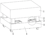
FIG. 1 is a schematic view of the front perspective structure of the present invention;
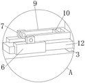
FIG. 2 is an enlarged schematic view of the structure at A of FIG. 1 according to the present invention;
FIG. 3 is a schematic front sectional view of the present invention;
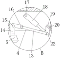
FIG. 4 is an enlarged schematic view of the structure of FIG. 3B according to the present invention;
fig. 5 is an enlarged schematic structural diagram of the present invention at C in fig. 3.
In the figure: 1. a pig machine body; 2. a connecting leg; 3. a fixing plate; 4. reinforcing the base body; 5. a universal wheel; 6. a fixed block; 7. connecting blocks; 9. a wrench; 10. a connecting rod; 12. a slide bar; 13. a support bar; 14. a first rotating lever; 15. a first rotating shaft; 16. a first hinge shaft; 17. a second rotating shaft; 18. a hydraulic lever; 19. a third rotating shaft; 20. a second rotating lever; 22. a second hinge shaft; 23. a tension spring.
Detailed Description
The technical solutions in the embodiments of the present invention will be described clearly and completely with reference to the accompanying drawings in the embodiments of the present invention, and it is obvious that the described embodiments are only some embodiments of the present invention, not all embodiments.
Referring to fig. 1 to 5, the present invention provides a technical solution: the strengthening base of the pig machine comprises connecting legs 2 and a strengthening base main body 4, wherein the lower ends of the connecting legs 2 are fixedly connected with a fixing plate 3, the upper ends of the connecting legs 2 are fixedly connected with a pig machine main body 1, the number of the connecting legs 2 is four, the four connecting legs 2 are distributed in a rectangular array, one side inside the strengthening base main body 4 is rotatably connected with a third rotating shaft 19, the outer surface of the third rotating shaft 19 is rotatably connected with a second rotating rod 20, one end of the second rotating rod 20 is rotatably connected with a second hinge shaft 22, the inside of the strengthening base main body 4 is rotatably connected with a second rotating shaft 17, the outer surface of the second rotating shaft 17 is rotatably connected with a hydraulic rod 18, the output end of the hydraulic rod 18 is fixedly connected with the second hinge shaft 22, the outer surface of the second hinge shaft 22 is rotatably connected with a supporting rod 13, one end of the supporting rod 13 is rotatably connected with a first hinge shaft 16, the shape of the first rotating rod 14 is L-shaped, the lower side inside the reinforcing base body 4 is rotatably connected with a first rotating shaft 15, the outer surface of the first rotating shaft 15 is rotatably connected with the first rotating rod 14, one end of the first rotating rod 14 is rotatably connected with a universal wheel 5, the number of the universal wheels 5 is four, the four universal wheels 5 are distributed in a rectangular array, the upper surface of the reinforcing base body 4 is fixedly connected with a fixed block 6, the inside of the fixed block 6 is slidably connected with a sliding rod 12, the upper surface of the fixed block 6 is fixedly connected with a connecting block 7, one side surface of the connecting block 7 is rotatably connected with a wrench 9 through a rotating shaft, the inside of the wrench 9 is fixedly connected with a connecting rod 10, one side surface of the connecting rod 10 is fixedly connected with an extension spring 23, the fixed block 6 is L-shaped, the wrench 9 is U-shaped, one, the number of the sliding rods 12 is four, and the four sliding rods 12 are distributed in a rectangular array.
When the universal wheel type cast iron machine is used, the output end of the hydraulic rod 18 pushes the second rotating rod 20 to rotate around the third rotating shaft 19 by pushing the second hinge shaft 22, one end of the hydraulic rod 18 is also rotationally connected with the reinforced base main body 4 through the second rotating shaft 17, so that the hydraulic rod 18 can rotate around the second rotating shaft 17 when in work, the third rotating shaft 19 pulls the supporting rod 13 through the second hinge shaft 22 while rotating, the supporting rod 13 pulls the first rotating rod 14 around the first rotating shaft 15 through the first hinge shaft 16, the universal wheel 5 extends out of the reinforced base main body 4, and the reinforced base main body 4 is slowly supported to leave the ground, so that the universal wheel 5 can move, and the cast iron machine main body 1 can be conveniently carried; after moving to a designated place, the hydraulic rod 18 can be controlled to contract to retract the universal wheels 5 into the reinforcing base body 4. Wrenching the spanner 9 and making it rotate around the axis of rotation, connecting rod 10 passes through extension spring 23 pulling slide bar 12 and slides in fixed block 6 simultaneously to press slide bar 12 at the upper surface of fixed plate 3 or break away from fixed plate 3, the dismouting to pig machine main part 1 on reinforcing base main part 4 is finally realized, and slide bar 12 compresses tightly fixed plate 3 back extension spring 23 can be fixed slide bar 12 moreover, prevents that pig machine during operation slide bar 12 from sliding.
To sum up, the utility model has the advantages that the universal wheel 5, the third rotating shaft 19, the second rotating rod 20, the second hinged shaft 22, the supporting rod 13, the first hinged shaft 16, the first rotating shaft 15, the first rotating rod 14 and the universal wheel 5 are arranged, the hydraulic rod 18 pushes the second hinged shaft 22 to drive the second rotating rod 20 to rotate and simultaneously pull the supporting rod 13 to move, the supporting rod 13 pulls the first rotating rod 14 to rotate through the first hinged shaft 16, so that the universal wheel 5 extends out of the reinforced base main body 4, the moving function is realized, the carrying is convenient, the wrench 9 rotates around the rotating shaft by arranging the fixing block 6, the sliding rod 12, the connecting block 7, the wrench 9, the connecting rod 10 and the tension spring 23, the connecting rod 10 pulls the sliding rod 12 to slide and press the fixing plate 3 through the tension spring 23, so that the cast iron machine main body 1 is fixed on the reinforced base main body 4, the structure is simple to operate, the iron casting machine main body 1 is convenient to disassemble and assemble.
The above, only be the concrete implementation of the preferred embodiment of the present invention, but the protection scope of the present invention is not limited thereto, and any person skilled in the art is in the technical scope of the present invention, according to the technical solution of the present invention and the utility model, the concept of which is equivalent to replace or change, should be covered within the protection scope of the present invention.
Claims (6)
1. The base is consolidated to pig machine, including connecting leg (2) and consolidating base main part (4), its characterized in that: the reinforced base is characterized in that one side of the interior of the reinforced base main body (4) is rotatably connected with a third rotating shaft (19), the outer surface of the third rotating shaft (19) is rotatably connected with a second rotating rod (20), one end of the second rotating rod (20) is rotatably connected with a second hinge shaft (22), the outer surface of the second hinge shaft (22) is rotatably connected with a supporting rod (13), one end of the supporting rod (13) is rotatably connected with a first hinge shaft (16), the outer surface of the first hinge shaft (16) is rotatably connected with a first rotating rod (14), one end of the first rotating rod (14) is rotatably connected with a universal wheel (5), the upper surface of the reinforced base main body (4) is fixedly connected with a fixed block (6), the interior of the fixed block (6) is slidably connected with a sliding rod (12), the upper surface of the fixed block (6) is fixedly connected with a, one side of the connecting block (7) is rotatably connected with a wrench (9) through a rotating shaft, the inside of the wrench (9) is fixedly connected with a connecting rod (10), and one side of the connecting rod (10) is fixedly connected with an extension spring (23).
2. The pig machine reinforced base of claim 1, wherein: the reinforced base is characterized in that a second rotating shaft (17) is rotatably connected to the inside of the reinforced base main body (4), a hydraulic rod (18) is rotatably connected to the outer surface of the second rotating shaft (17), and the output end of the hydraulic rod (18) is fixedly connected with a second hinge shaft (22).
3. The pig machine reinforced base of claim 1, wherein: the shape of first pivot pole (14) is the L type, the inside downside of consolidating base main part (4) is rotated and is connected with first pivot (15), the surface and the rotation of first pivot (15) are connected with first pivot pole (14).
4. The pig machine reinforced base of claim 1, wherein: the number of the universal wheels (5) is four, and the four universal wheels (5) are distributed in a rectangular array.
5. The pig machine reinforced base of claim 1, wherein: the shape of fixed block (6) is the L type, the shape of spanner (9) is the U type, extension spring (23) keep away from the one end and the slide bar (12) fixed connection of connecting rod (10), the quantity of slide bar (12) is four, four slide bar (12) are the rectangle array and distribute.
6. The pig machine reinforced base of claim 1, wherein: the lower extreme fixedly connected with fixed plate (3) of connecting leg (2), the upper end fixedly connected with pig machine main part (1) of connecting leg (2), the quantity of connecting leg (2) is four, four connecting leg (2) are the rectangular array and distribute.
Priority Applications (1)
| Application Number | Priority Date | Filing Date | Title |
|---|---|---|---|
| CN202022143928.9U CN213317543U (en) | 2020-09-27 | 2020-09-27 | Cast iron machine reinforcing base |
Applications Claiming Priority (1)
| Application Number | Priority Date | Filing Date | Title |
|---|---|---|---|
| CN202022143928.9U CN213317543U (en) | 2020-09-27 | 2020-09-27 | Cast iron machine reinforcing base |
Publications (1)
| Publication Number | Publication Date |
|---|---|
| CN213317543U true CN213317543U (en) | 2021-06-01 |
Family
ID=76067881
Family Applications (1)
| Application Number | Title | Priority Date | Filing Date |
|---|---|---|---|
| CN202022143928.9U Active CN213317543U (en) | 2020-09-27 | 2020-09-27 | Cast iron machine reinforcing base |
Country Status (1)
| Country | Link |
|---|---|
| CN (1) | CN213317543U (en) |
-
2020
- 2020-09-27 CN CN202022143928.9U patent/CN213317543U/en active Active
Similar Documents
| Publication | Publication Date | Title |
|---|---|---|
| CN105500518A (en) | Prefabricated stair production line and production method | |
| CN213317543U (en) | Cast iron machine reinforcing base | |
| CN218255834U (en) | Component formwork for concrete structure prefabricated panel production and pouring | |
| CN209579992U (en) | A kind of bimodulus group production line of heat insulation building block | |
| CN206328776U (en) | A kind of pipe gallery construction vehicle die assembly | |
| CN219666968U (en) | Segment production equipment | |
| CN207808021U (en) | A kind of slip casting machine switching mechanism | |
| CN211279372U (en) | Quick demoulding mould for mutual inductor | |
| CN118342639A (en) | Mould is used in processing of precast cement square pile | |
| CN201056031Y (en) | Feeding arrangement of concrete pile | |
| CN216656173U (en) | Tubular pile steel reinforcement cage welding device for tubular pile production | |
| CN112024851B (en) | Water pump impeller casting molding shakeout processing system | |
| CN109382906A (en) | A kind of bimodulus group production line of heat insulation building block | |
| CN211469995U (en) | Mould grabbing device of mould production usefulness | |
| CN208979844U (en) | A kind of concrete precast block handling device | |
| CN221878870U (en) | A concrete pouring equipment | |
| CN214394989U (en) | Novel anti-settling well lid installation cover die | |
| CN222156006U (en) | Curing means for concrete experiments | |
| CN222681268U (en) | A steam-curing kiln auxiliary traction device for electric pole production | |
| CN221066770U (en) | High-efficient agitating unit of concrete | |
| CN217972033U (en) | Cable lifting device for distribution network construction | |
| CN219634112U (en) | Drawing die device for producing wire drawing disc | |
| CN223164263U (en) | Form removing machine for concrete engineering | |
| CN222448168U (en) | A sand box for metal casting | |
| CN215907764U (en) | Concrete slab drilling equipment for building construction |
Legal Events
| Date | Code | Title | Description |
|---|---|---|---|
| GR01 | Patent grant | ||
| GR01 | Patent grant |