CN214166322U - Steel bottle welding seam detection line - Google Patents
Steel bottle welding seam detection line Download PDFInfo
- Publication number
- CN214166322U CN214166322U CN202023309199.6U CN202023309199U CN214166322U CN 214166322 U CN214166322 U CN 214166322U CN 202023309199 U CN202023309199 U CN 202023309199U CN 214166322 U CN214166322 U CN 214166322U
- Authority
- CN
- China
- Prior art keywords
- frame
- feeding
- rotary platform
- section
- welding seam
- Prior art date
- Legal status (The legal status is an assumption and is not a legal conclusion. Google has not performed a legal analysis and makes no representation as to the accuracy of the status listed.)
- Expired - Fee Related
Links
- 238000001514 detection method Methods 0.000 title claims abstract description 31
- 238000003466 welding Methods 0.000 title claims abstract description 27
- 229910000831 Steel Inorganic materials 0.000 title claims abstract description 23
- 239000010959 steel Substances 0.000 title claims abstract description 23
- 238000007599 discharging Methods 0.000 claims description 24
- 239000000463 material Substances 0.000 claims description 23
- 230000005484 gravity Effects 0.000 claims description 4
- 238000007689 inspection Methods 0.000 claims description 4
- 238000007664 blowing Methods 0.000 description 5
- 238000010586 diagram Methods 0.000 description 3
- 238000000034 method Methods 0.000 description 2
- 238000012986 modification Methods 0.000 description 2
- 230000004048 modification Effects 0.000 description 2
- 230000009286 beneficial effect Effects 0.000 description 1
- 230000007547 defect Effects 0.000 description 1
- 230000000694 effects Effects 0.000 description 1
- 238000005516 engineering process Methods 0.000 description 1
- 230000002452 interceptive effect Effects 0.000 description 1
Images

Landscapes
- Butt Welding And Welding Of Specific Article (AREA)
Abstract
The utility model provides a steel bottle welding seam detection line, which comprises a frame, set gradually feeding section, detection station and ejection of compact section in the frame, the feeding section with the ejection of compact section all adopts step-by-step pay-off structure, it includes rotary platform to detect the station, rotary platform's below is equipped with the base, rotary platform is through locating the servo motor cooperation gear train drive of base below rotates, the last wire casing that supplies feeding or ejection of compact to use that is equipped with of rotary platform, rotary platform's both sides still are equipped with the support, be equipped with welding seam detecting instrument on the support. The utility model discloses a step-by-step pay-off structure combines the detection station, has realized pay-off in proper order, has detected and the ejection of compact, accomplishes automatic welding seam and detects, has improved welding seam detection efficiency.
Description
Technical Field
The utility model relates to a welding seam detection area, in particular to steel bottle welding seam detection line.
Background
The welding quality detection refers to the detection of welding results, and aims to ensure the integrity, reliability, safety and usability of a welding structure. In addition to the requirements for welding technology and welding process, weld quality inspection is also an important part of the quality management of welded structures.
The existing steel cylinder needs to detect the welding seam, the traditional detection method is time-consuming and labor-consuming, and the detection efficiency is low.
Therefore, aiming at the defects existing in the prior art, a steel cylinder welding line needs to be designed to improve the detection efficiency.
SUMMERY OF THE UTILITY MODEL
For overcoming the not enough among the above-mentioned prior art, the utility model aims to provide a steel bottle welding seam detection line.
In order to achieve the above objects and other related objects, the present invention provides a technical solution: the utility model provides a steel bottle welding seam detection line, includes the frame, set gradually feeding section, detection station and play material section in the frame, the feeding section with it all adopts step-by-step pay-off structure to go out the material section, it includes rotary platform to detect the station, rotary platform's below is equipped with the base, rotary platform is through locating the servo motor cooperation gear train drive of base below rotates, the last wire casing that supplies feeding or ejection of compact to use that is equipped with of rotary platform, rotary platform's both sides still are equipped with the support, be equipped with welding seam detecting instrument on the support.
The preferable technical scheme is as follows: the feeding device is characterized in that the rack is provided with a feeding frame at the feeding section and a discharging frame at the discharging section, a track is arranged on the inner side of the feeding frame, a movable frame is arranged in the track in a sliding mode, and the movable frame is driven by a cylinder to reciprocate in the track.
The preferable technical scheme is as follows: a plurality of stop blocks and movable blocks are arranged at equal intervals and correspondingly on the inner side of the movable frame; the movable block is triangular and is arranged in a rotating mode, the material forking angle of the movable block extends out of the surface of the material placing frame under the influence of gravity, the movable block is in interference with a workpiece arranged on the material placing frame under the reciprocating motion of the movable frame so as to rotate in a reciprocating mode in a clockwise and anticlockwise mode, and the stop block is arranged on one side, close to the discharge end, of the movable block and is opposite to the side, rotating in the anticlockwise mode, of the movable block so as to cause interference and guarantee that the material forking angle is located above the surface of the material placing frame and push the workpiece to be stepped.
The preferable technical scheme is as follows: the movable frames in the feeding section and the discharging section are driven by the air cylinder in the feeding section or the discharging section to be inserted into the wire groove for feeding or discharging when the rotary platform feeds or discharges materials.
Because of the application of the technical scheme, the utility model discloses the beneficial effect who has does:
the utility model discloses a step-by-step pay-off structure combines the detection station, has realized pay-off in proper order, has detected and the ejection of compact, accomplishes automatic welding seam and detects, has improved welding seam detection efficiency.
Drawings
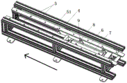
Fig. 1 is a structural schematic of the present invention.
Fig. 2 is the structure schematic diagram of the feeding section and the discharging section of the utility model.
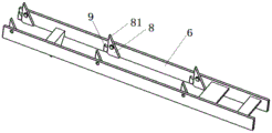
Fig. 3 is the assembly schematic diagram of the movable frame, the movable block and the stop block of the present invention.
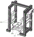
Fig. 4 is the utility model discloses detect station structure schematic diagram.
In the above figures, 1, a feeding section; 2. detecting a station; 3. a discharging section; 4. a frame; 5. a material placing frame; 51. a track; 6. a movable frame; 7. a cylinder; 8. a movable block; 81. a material forking angle; 9. a stopper; 10. rotating the platform; 101. a wire slot; 11. a base; 12. weld joint detection instrument.
Detailed Description
The following description is provided for illustrative purposes, and other advantages and features of the present invention will become apparent to those skilled in the art from the following detailed description.
Please refer to fig. 1-4. It should be understood that in the description of the present invention, it should be noted that the terms "center", "upper", "lower", "left", "right", "vertical", "horizontal", "inner", "outer", etc. indicate the position or positional relationship based on the position or positional relationship shown in the drawings, or the position or positional relationship that the product of the present invention is usually placed when in use, and are only for convenience of describing the present invention and simplifying the description, but do not indicate or imply that the device or element to which the term refers must have a specific position, be constructed and operated in a specific orientation, and thus, should not be construed as limiting the present invention. Furthermore, the terms "first," "second," "third," and the like are used solely to distinguish one from another and are not to be construed as indicating or implying relative importance. The terms "horizontal", "vertical", "overhang" and the like do not imply that the components are required to be absolutely horizontal or overhang, but may be slightly inclined. For example, "horizontal" merely means that the direction is more horizontal than "vertical" and does not mean that the structure must be perfectly horizontal, but may be slightly inclined.
In the description of the present invention, it should be further noted that, unless otherwise explicitly stated or limited, the terms "disposed," "mounted," "connected," and "connected" are to be construed broadly and may include, for example, a fixed connection, a detachable connection, an integral connection, a mechanical connection, an electrical connection, a direct connection, an indirect connection via an intermediate medium, and a connection between two elements. The specific meaning of the above terms in the present invention can be understood in specific cases to those skilled in the art.
Example (b):
as shown in FIG. 1, for the utility model provides a steel bottle weld detection line, including frame 4. A feeding section 1, a detection station 2 and a discharging section 3 are sequentially arranged on the frame 4.
Wherein, all be equipped with blowing frame 5 in feeding section 1 and ejection of compact section 3 on the frame 4, the inboard of blowing frame 5 is equipped with track 51, and it is equipped with adjustable shelf 6 to slide in track 51, and adjustable shelf 6 carries out reciprocating motion in track 51 under the drive of cylinder 7. The cylinder 7 is arranged below the discharging frame 5 and arranged along the discharging frame 5.
Furthermore, a plurality of stop blocks 9 and movable blocks 8 are arranged at equal intervals and correspondingly on the inner side of the movable frame 6
Wherein, the movable block 8 is triangle-shaped and rotates and sets up, and the inclined gravity of movable block 8 influences its fork material angle 81 above blowing frame 5 face, and movable block 8 forms the interference with the steel bottle of locating on blowing frame 5 under the reciprocating motion of movable frame 6 so that carry out reciprocal clockwise, anticlockwise rotation.
The dog 9 is located the movable block 8 and is close to one side of discharge end and rotates in the reverse time to the movable block 8 and cause the interference in order to ensure that fork material angle 81 is located the blowing frame 5 above the face to it is step-by-step to promote the steel bottle.
The detection station 2 comprises a rotary platform 10, a base 11 is arranged below the rotary platform 10, and the rotary platform 10 is driven to rotate by a servo motor arranged below the base 11 and matched with a gear set. The rotary platform 10 is provided with a wire groove 101 for feeding or discharging, the two sides of the rotary platform 10 are also provided with supports, and the supports are provided with a weld joint detector 12 for detecting the weld joint of the steel cylinder.
The movable frames 6 on the frame 4 in the feeding section 1 and the discharging section 3 are driven by the air cylinder 7 to be inserted into the wire groove 101 for feeding or discharging when the rotary platform 10 feeds or discharges materials.
The feeding and discharging principle is as follows:
the movable frame 6 moves towards the feeding end under the driving of the air cylinder 7, the movable block 8 and a steel cylinder arranged on the discharging frame 5 rotate clockwise after interference is formed, and the movable block 8 rotates clockwise until the fork angle 81 is positioned below the discharging frame 5 and then forms interference with the stop block 9 to stop rotating; when the movable block 8 strides over from the bottom of the steel cylinder, the movable block 8 is reset under the influence of the gravity, and a material fork angle 81 of the movable block extends out of the frame surface of the material placing frame 5; at this point, the fork angle 81 completes the movement from the steel cylinder discharge side to the steel cylinder feed side; then, the movable frame 6 is reset (moves towards the discharge end) under the driving of the cylinder 7, the material forking angle 81 of the movable block 8 positioned on the feeding side of the steel cylinder forms interference with the steel cylinder to cause the movable block 8 to rotate reversely, the stop block 9 forms interference on the reverse rotation of the movable block 8 to ensure that the material forking angle on the feeding side of the steel cylinder keeps interfering with the workpiece to drive the steel cylinder to complete stepping towards the discharge end on the discharge frame 5;
the process comprises the following steps:
(1) under the coordination of the rotary platform, the movable frame of the feeding section extends into the wire groove to convey the steel cylinder to the rotary platform and then reset;
(2) the rotary platform is matched with a welding line detection instrument in a rotating mode to carry out welding line detection;
(3) under the cooperation of the rotary platform, the discharge section movable frame extends into the wire groove to take out the steel cylinder from the rotary platform, and the operation is repeated according to the above.
Therefore, the utility model has the advantages of it is following:
the utility model discloses a step-by-step pay-off structure combines the detection station, has realized pay-off in proper order, has detected and the ejection of compact, accomplishes automatic welding seam and detects, has improved welding seam detection efficiency.
The above embodiments are merely illustrative of the principles and effects of the present invention, and are not to be construed as limiting the invention. Modifications and variations can be made to the above-described embodiments by those skilled in the art without departing from the spirit and scope of the present invention. Accordingly, it is intended that all equivalent modifications or changes which may be made by those skilled in the art without departing from the spirit and technical spirit of the present invention be covered by the claims of the present invention.
Claims (4)
1. The utility model provides a steel bottle welding seam detection line, includes the frame, its characterized in that: the welding seam detection device is characterized in that a feeding section, a detection station and a discharging section are sequentially arranged on the rack, the feeding section and the discharging section are of a stepping feeding structure, the detection station comprises a rotary platform, a base is arranged below the rotary platform, the rotary platform is driven to rotate by a servo motor matched with a gear set below the base, a wire groove for feeding or discharging is formed in the rotary platform, supports are arranged on two sides of the rotary platform, and welding seam detection instruments are arranged on the supports.
2. The cylinder weld inspection line of claim 1, wherein: the feeding device is characterized in that the rack is provided with a feeding frame at the feeding section and a discharging frame at the discharging section, a track is arranged on the inner side of the feeding frame, a movable frame is arranged in the track in a sliding mode, and the movable frame is driven by a cylinder to reciprocate in the track.
3. The cylinder weld inspection line of claim 2, wherein: a plurality of stop blocks and movable blocks are arranged at equal intervals and correspondingly on the inner side of the movable frame; the movable block is triangular and is arranged in a rotating mode, the material forking angle of the movable block extends out of the surface of the material placing frame under the influence of gravity, the movable block is in interference with a workpiece arranged on the material placing frame under the reciprocating motion of the movable frame so as to rotate in a reciprocating mode in a clockwise and anticlockwise mode, and the stop block is arranged on one side, close to the discharge end, of the movable block and is opposite to the side, rotating in the anticlockwise mode, of the movable block so as to cause interference and guarantee that the material forking angle is located above the surface of the material placing frame and push the workpiece to be stepped.
4. The cylinder weld inspection line of claim 2, wherein: the movable frames in the feeding section and the discharging section are driven by the air cylinder in the feeding section or the discharging section to be inserted into the wire groove for feeding or discharging when the rotary platform feeds or discharges materials.
Priority Applications (1)
| Application Number | Priority Date | Filing Date | Title |
|---|---|---|---|
| CN202023309199.6U CN214166322U (en) | 2020-12-30 | 2020-12-30 | Steel bottle welding seam detection line |
Applications Claiming Priority (1)
| Application Number | Priority Date | Filing Date | Title |
|---|---|---|---|
| CN202023309199.6U CN214166322U (en) | 2020-12-30 | 2020-12-30 | Steel bottle welding seam detection line |
Publications (1)
| Publication Number | Publication Date |
|---|---|
| CN214166322U true CN214166322U (en) | 2021-09-10 |
Family
ID=77611366
Family Applications (1)
| Application Number | Title | Priority Date | Filing Date |
|---|---|---|---|
| CN202023309199.6U Expired - Fee Related CN214166322U (en) | 2020-12-30 | 2020-12-30 | Steel bottle welding seam detection line |
Country Status (1)
| Country | Link |
|---|---|
| CN (1) | CN214166322U (en) |
-
2020
- 2020-12-30 CN CN202023309199.6U patent/CN214166322U/en not_active Expired - Fee Related
Similar Documents
| Publication | Publication Date | Title |
|---|---|---|
| CN208195985U (en) | A kind of automatic soldering device | |
| CN104551394B (en) | Battery production Full-automatic laser welding equipment | |
| CN115463858B (en) | Automatic detection device and detection method for aluminum bottle | |
| CN205703008U (en) | The automatic welding device that the leading group of a kind of boat segmental is vertical | |
| CN110940274A (en) | Full-automatic detection line for size of inner cavity of revolving body | |
| CN102091870A (en) | Fiber transmission automatic laser welding system dedicated for plate type solar thermal collector | |
| CN207104111U (en) | Battery welder | |
| CN219358268U (en) | Stator laser welding machine | |
| CN114473205A (en) | Error compensation type laser welding equipment with crack detection | |
| CN116315491A (en) | A tab pre-welding machine | |
| CN213364614U (en) | Cylindrical capacitor appearance flaw detection device | |
| CN205002759U (en) | Automatic mechanism of proofreading of deep groove ball bearing inner circle standard component | |
| CN114309933A (en) | Stator pressure welding measurement production line | |
| CN111085459A (en) | Automatic marking off detection device of pen | |
| CN207114479U (en) | A kind of flaw detection platform for bar automatic flaw detection apparatus | |
| CN207114559U (en) | A kind of bar automatic flaw detection apparatus | |
| CN209452185U (en) | A kind of point glue equipment | |
| CN107367623A (en) | A kind of bar automatic flaw detection apparatus | |
| CN214174365U (en) | Detection apparatus for welded tube welding seam | |
| CN208766121U (en) | Aluminum alloy piston automatic detection device | |
| CN112945679A (en) | Automatic change impact specimen breach burring device | |
| CN209811422U (en) | Device for automatically detecting arc welding starting point and end point | |
| CN216939072U (en) | Double-welding-head welding machine | |
| CN109482522A (en) | Substandard products pick material component | |
| CN210922512U (en) | Full-automatic detection line for size of inner cavity of revolving body |
Legal Events
| Date | Code | Title | Description |
|---|---|---|---|
| GR01 | Patent grant | ||
| GR01 | Patent grant | ||
| CF01 | Termination of patent right due to non-payment of annual fee |
Granted publication date: 20210910 |
|
| CF01 | Termination of patent right due to non-payment of annual fee |