CN215550960U - 3D printer extrusion structure - Google Patents
3D printer extrusion structure Download PDFInfo
- Publication number
- CN215550960U CN215550960U CN202121114552.7U CN202121114552U CN215550960U CN 215550960 U CN215550960 U CN 215550960U CN 202121114552 U CN202121114552 U CN 202121114552U CN 215550960 U CN215550960 U CN 215550960U
- Authority
- CN
- China
- Prior art keywords
- extrusion
- hobbing
- printer
- gear
- adjusting bracket
- Prior art date
- Legal status (The legal status is an assumption and is not a legal conclusion. Google has not performed a legal analysis and makes no representation as to the accuracy of the status listed.)
- Active
Links
- 238000001125 extrusion Methods 0.000 title claims abstract description 137
- 238000010438 heat treatment Methods 0.000 claims description 45
- 230000017525 heat dissipation Effects 0.000 claims description 37
- 230000009467 reduction Effects 0.000 claims description 22
- 238000007599 discharging Methods 0.000 claims description 10
- 238000009413 insulation Methods 0.000 claims description 4
- 230000005855 radiation Effects 0.000 claims 2
- 239000000463 material Substances 0.000 abstract description 14
- 230000033228 biological regulation Effects 0.000 abstract description 3
- 238000010146 3D printing Methods 0.000 abstract description 2
- 238000007639 printing Methods 0.000 description 8
- 238000009434 installation Methods 0.000 description 7
- 239000004033 plastic Substances 0.000 description 5
- 238000001816 cooling Methods 0.000 description 4
- 238000010586 diagram Methods 0.000 description 4
- 230000009471 action Effects 0.000 description 3
- 230000000694 effects Effects 0.000 description 3
- 235000000621 Bidens tripartita Nutrition 0.000 description 2
- 240000004082 Bidens tripartita Species 0.000 description 2
- 239000004809 Teflon Substances 0.000 description 2
- 229920006362 Teflon® Polymers 0.000 description 2
- 208000006637 fused teeth Diseases 0.000 description 2
- 238000000034 method Methods 0.000 description 2
- 230000008569 process Effects 0.000 description 2
- 238000003756 stirring Methods 0.000 description 2
- 230000006978 adaptation Effects 0.000 description 1
- 229910052782 aluminium Inorganic materials 0.000 description 1
- XAGFODPZIPBFFR-UHFFFAOYSA-N aluminium Chemical compound [Al] XAGFODPZIPBFFR-UHFFFAOYSA-N 0.000 description 1
- 230000008901 benefit Effects 0.000 description 1
- 230000005540 biological transmission Effects 0.000 description 1
- 230000006872 improvement Effects 0.000 description 1
- 239000011810 insulating material Substances 0.000 description 1
- 239000007769 metal material Substances 0.000 description 1
- 230000004048 modification Effects 0.000 description 1
- 238000012986 modification Methods 0.000 description 1
- 230000000149 penetrating effect Effects 0.000 description 1
- 230000035515 penetration Effects 0.000 description 1
- 229920001296 polysiloxane Polymers 0.000 description 1
- 238000000926 separation method Methods 0.000 description 1
- 125000003003 spiro group Chemical group 0.000 description 1
- 238000006467 substitution reaction Methods 0.000 description 1
Images



Abstract
The utility model discloses an extrusion structure of a 3D printer, and belongs to the technical field of 3D printing. 3D printer extrusion structure includes: a housing; the motor is arranged on the shell; the driving extrusion gear hobbing is arranged in the shell and is connected with the motor; the adjusting bracket is rotatably connected in the shell; the driven extrusion gear hobbing is arranged at one end of the adjusting bracket and is rotationally connected with the adjusting bracket; the elastic piece is connected with the other end of the adjusting bracket, so that one end of the adjusting bracket, which is provided with the driven extrusion hobbing, is close to the driving extrusion hobbing, and the driven extrusion hobbing is matched with the driving extrusion hobbing to finish material extrusion; wherein, the regulation support is provided with the one end of driven gear hobbing is worn out to the outside of casing. The utility model discloses a 3D printer extrusion structure that small, the quality is light, the steady accuracy of pay-off and be convenient for operate.
Description
Technical Field
The utility model relates to the technical field of 3D printing, in particular to an extrusion structure of a 3D printer.
Background
In the 3D printer, the structure of extruding is the nozzle department that is located the 3D printer with the material heating and extrude from the nozzle, and the stability of extruding the structure plays the key role to printing quality and printing stability. The traditional extrusion structure has larger volume and weight, not only occupies large space and has high cost, but also causes large load of the printer due to the larger volume and weight, and is not suitable for near-end and ultra-near-end printing. In addition, some existing extrusion structures adopt single-tooth feeding, so that feeding is not stable enough, and the feeding stability and accuracy are poor.
SUMMERY OF THE UTILITY MODEL
In order to solve the technical problems, the utility model provides the 3D printer extrusion structure which is small in size, light in weight, stable and accurate in feeding and convenient to operate.
In order to achieve the purpose, the utility model adopts the following technical scheme:
a 3D printer extrusion structure comprising:
a housing;
the motor is arranged on the shell;
the driving extrusion gear hobbing is arranged in the shell and is connected with the motor;
the adjusting bracket is rotatably connected in the shell;
the driven extrusion gear hobbing is arranged at one end of the adjusting bracket and is rotationally connected with the adjusting bracket;
the elastic piece is connected with the other end of the adjusting bracket, so that one end of the adjusting bracket, which is provided with the driven extrusion hobbing, is close to the driving extrusion hobbing, and the driven extrusion hobbing is matched with the driving extrusion hobbing to finish material extrusion;
wherein, the regulation support is provided with the one end of driven gear hobbing is worn out to the outside of casing.
As an alternative of the above 3D printer extrusion structure, the 3D printer extrusion structure further includes:
the motor gear is connected with the motor;
the gear rotating shaft is rotatably connected in the shell;
the reduction gear is arranged on the gear rotating shaft and meshed with the motor gear, the outer diameter of the reduction gear is larger than that of the motor gear, and the active extrusion gear hobbing is arranged on the gear rotating shaft and rotates coaxially with the reduction gear.
As an alternative of the above 3D printer extrusion structure, the 3D printer extrusion structure further includes:
the heat dissipation piece is arranged below the driving extrusion hobbing and the driven extrusion hobbing;
the first discharge pipe is arranged in the heat dissipation part and used for discharging consumables of the 3D printer;
the throat pipe is sleeved outside the first discharging pipe, and one end of the throat pipe is in contact with the heat radiating piece;
the first heat dissipation fan and the first air guide piece are arranged on the shell, and the first air guide piece can guide air blown out by the first heat dissipation fan to the heat dissipation piece.
As an alternative of the above 3D printer extrusion structure, the 3D printer extrusion structure further includes:
the heating block is arranged below the heat radiating piece, and the other end of the throat pipe is in contact with the heating block;
the nozzle is arranged at the bottom end of the heating block, and the consumable passes through the heat dissipation piece and the heating block in sequence and then is sprayed out of the nozzle;
and the heating pipe is arranged on the heating block and used for heating the consumable materials in the heating block.
As an alternative to the above-described 3D printer extrusion structure, the outer periphery of the reduction gear protrudes to the outside of the housing.
As an alternative of the above 3D printer extrusion structure, the 3D printer extrusion structure further includes:
and the second cooling fan and the second air guide piece are arranged on the shell, and the second air guide piece can guide the air of the second cooling fan to the model below the 3D printer extrusion structure.
As an alternative of the above 3D printer extrusion structure, the 3D printer extrusion structure further includes:
the installation screw, be provided with in the casing and be used for the installation the screens of installation screw, installation screw locates in the screens, the elastic component cover is located on the installation screw.
As an alternative of the above 3D printer extrusion structure, the other end of the adjusting bracket has a first side and a second side along the rotation direction thereof, the first side is connected with the elastic member, and a limiting structure corresponding to the second side is provided in the casing to limit the adjusting bracket.
As an alternative of the extrusion structure of the 3D printer, a thermistor is arranged in the heating block.
As an alternative of the extrusion structure of the 3D printer, the surface of the heating block is sleeved with a heat insulation piece.
The 3D printer extrusion structure adopts a double-tooth feeding mode, the active extrusion hobbing is matched with the driven extrusion hobbing to realize extrusion of consumables, and stable and accurate feeding can be realized. The regulation support of the installation driven gear hobbing of extruding stretches out to the casing outside, when needs penetrate the consumptive material, stirs from the casing outside and adjusts the support and can make driven gear hobbing and the separation of initiatively extruding the gear hobbing to penetrate consumptive material, convenient operation. Meanwhile, the 3D printer extrusion structure is small in size and light in weight, can achieve miniaturization and light weight of the extrusion structure, and can adapt to near-end and super-near-end printing.
Drawings
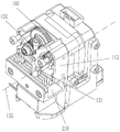
FIG. 1 is a schematic perspective view of an extrusion structure of a 3D printer according to the present invention;
FIG. 2 is a schematic diagram of the internal structure of the 3D printer extrusion structure of the present invention;
FIG. 3 is an exploded view of the extrusion structure of the 3D printer of the present invention;
FIG. 4 is a schematic diagram of a front view of an extrusion structure of the 3D printer according to the present invention;
FIG. 5 is a schematic cross-sectional view of section A-A of FIG. 4;
FIG. 6 is a front view schematic diagram of the structure shown in FIG. 2;
FIG. 7 is a schematic structural diagram of the 3D printer extrusion structure during consumable penetration.
In the figure:
101. consumable materials; 110. a housing; 111. a front housing; 112. a rear housing; 120. a motor; 130. actively extruding and hobbing; 131. a first rotating pin; 132. a rotational axis; 140. adjusting the bracket; 141. mounting screws; 142. a limiting structure; 150. driven extrusion gear hobbing; 151. a second rotating pin; 152. a first plastic flange bearing; 153. a second plastic flange bearing; 160. an elastic member; 170. a motor gear; 180. a gear shaft; 181. a bearing; 190. a reduction gear; 200. a heat sink; 210. a first discharge pipe; 211. a second discharge pipe; 212. a feed conduit; 220. a throat; 230. a first heat dissipation fan; 240. a first air guide member; 241. a first air guide opening; 250. a heating block; 251. a thermal insulation member; 252. a thermistor; 260. a nozzle; 270. heating a tube; 280. a second heat dissipation fan; 290. a second wind guide member; 291. and the second air guide opening.
Detailed Description
The present invention will be described in further detail with reference to the accompanying drawings and examples. It is to be understood that the specific embodiments described herein are merely illustrative of the utility model and are not limiting of the utility model. It should be further noted that, for the convenience of description, only some of the structures related to the present invention are shown in the drawings, not all of the structures.
The utility model provides an extrusion structure of a 3D printer, please refer to fig. 1 to 6, the extrusion structure of the 3D printer includes a housing 110, a motor 120, a driving extrusion gear 130, an adjusting bracket 140, a driven extrusion gear 150, and an elastic member 160. The housing 110 may include a front shell 111 and a rear shell 112, but the number of the components of the housing 110 may be adjusted as required, for example, the housing may include a plurality of segments that are spliced together, and is not limited herein.
The motor 120 is disposed on the housing 110, in an embodiment, the motor 120 is disposed on a rear side of the housing 110, and the motor 120 is disposed outside the housing 110, and the housing 110 is positioned and installed through a positioning hole on a chassis of the motor 120. The rotor of the motor 120 penetrates the inside of the housing 110, and the active extrusion hobbing 130 is disposed in the housing 110 and connected with the rotor of the motor 120, so that the motor 120 drives the active extrusion hobbing 130 to rotate. The driving extrusion hobbing 130 and the motor 120 can be directly connected, or indirectly connected through other intermediate transmission structures, and in the utility model, the driving extrusion hobbing 130 and the motor 120 are indirectly connected.
The adjustment bracket 140 is rotatably coupled within the housing 110. As shown in fig. 2 and 3, the adjusting bracket 140 is rotatably coupled to the housing 110 by a first rotating pin 131, so that the adjusting bracket 140 can rotate about the rotating axis 132. Preferably, one end of the first rotating pin 131 is supported on the front case 111, and the other end is supported on the rear case 112. As shown in fig. 6, the driven extrusion hobbing 150 is disposed at one end of the adjusting bracket 140 and is rotatably connected with the adjusting bracket 140, and the driven extrusion hobbing 150 can rotate on the adjusting bracket 140 to realize feeding. The elastic member 160 is connected with the other end of the adjusting bracket 140, the elastic member 160 enables one end of the adjusting bracket 140, which is provided with the driven extrusion hobbing 150, to approach the driving extrusion hobbing 130 so as to compress the consumable 101, the driven extrusion hobbing 150 is matched with the driving extrusion hobbing 130 to complete material extrusion, and the consumable 101 is clamped between the driving extrusion hobbing 130 and the driven extrusion hobbing 150 and is extruded outwards along with the rotation of the hobbing. The 3D printer extrusion structure has the advantage that feeding is stable and accurate through the double-tooth feeding mode of matching the driving extrusion hobbing 130 and the driven extrusion hobbing 150.
Referring to fig. 4 and 6, one end of the adjusting bracket 140, on which the driven extrusion gear 150 is disposed, extends out of the housing 110 to form a driving lever located outside the housing 110, and the driving lever is driven to drive the adjusting bracket 140 to rotate the adjusting bracket 140 clockwise around the rotation axis 132, referring to fig. 7, so that the driven extrusion gear 150 is separated from the driving extrusion gear 130, and thus the consumable 101 can be inserted between the driven extrusion gear 150 and the driving extrusion gear 130. In the process of stirring the adjusting bracket 140, the elastic part 160 is compressed, the consumable 101 penetrates into the adjusting bracket 140, and the adjusting bracket 140 is released and can reset under the elastic action of the elastic part 160, so that the driven extrusion gear hobbing 150 and the driving extrusion gear hobbing 130 are matched together again, the consumable 101 is clamped, and feeding is started. That is to say, the 3D printer extrusion structure of the present invention can realize the material penetrating operation only by shifting the portion of the adjusting bracket 140 located outside the housing 110, which is convenient and fast. Meanwhile, the 3D printer extrusion structure is small in size and light in weight, can achieve miniaturization and light weight of the extrusion structure, and can adapt to near-end and super-near-end printing.
Further, as shown in fig. 3 and 6, the driven extrusion hobbing 150 is rotatably connected to the adjustment bracket 140 through a second rotating pin 151. Specifically, both ends of the second rotating pin 151 are respectively supported at the front and rear sides of the adjusting bracket 140, and the front and rear ends of the driven extrusion gear 150 are respectively pressed into the first plastic flange bearing 152 and the second plastic flange bearing 153 and then penetrate into the second rotating pin 151.
As shown in fig. 6, the 3D printer extrusion structure of the present invention further includes a mounting screw 141, a clamping portion for mounting the mounting screw 141 is disposed in the housing 110, the mounting screw 141 is disposed in the clamping portion, the elastic member 160 may be a spring, and the spring is sleeved on the mounting screw 141 to achieve guiding of the spring. As shown in fig. 6, one end of the spring is sleeved on the mounting screw 141, and the other end abuts against the adjusting bracket 140, so that the spring pushes the adjusting bracket 140 against the active extrusion hobbing 130. When the material needs to be penetrated, the driven extrusion hobbing 150 and the driving extrusion hobbing 130 can be separated only by pressing the adjusting bracket 140 along the direction shown by the arrow in fig. 6 so as to penetrate the consumable 101 between the driven extrusion hobbing and the driving extrusion hobbing, the spring is compressed in the pressing process, and the adjusting bracket 140 can reset under the action of the spring after the adjusting bracket 140 is released.
Referring to fig. 6, one end of the adjusting bracket 140 connected to the elastic member 160 has a first side and a second side along the rotation direction thereof, the first side is connected to the elastic member 160, and a limiting structure 142 corresponding to the second side is disposed in the housing 110 to limit the adjusting bracket 140. In this embodiment, as shown in fig. 6, the limiting structure 142 is a stopping wall surface, which can stop the adjusting bracket 140 to limit the extrusion limit position, so as to avoid the material breakage caused by too large extrusion force of the adjusting bracket 140 toward the active extrusion hobbing 130 under the action of the spring. Meanwhile, the spring enables the adjusting bracket 140 to have certain extrusion force, and the situation that the material is planed due to the fact that the extrusion force is too small is avoided.
As shown in fig. 3, the 3D printer extrusion structure further includes a motor gear 170, a gear rotating shaft 180, and a reduction gear 190, the motor gear 170 is connected to the rotor of the motor 120, and the gear rotating shaft 180 is rotatably connected in the housing 110, specifically, as shown in fig. 3, the gear rotating shaft 180 is rotatably connected in the housing 110 through a bearing 181. The reduction gear 190 is provided on the gear rotating shaft 180 and engages with the motor gear 170. The outer diameter of the reduction gear 190 is larger than that of the motor gear 170, so that the motor gear 170 with a smaller diameter is meshed with the reduction gear 190 with a larger diameter to form a first-stage speed reduction, the active extrusion hobbing gear 130 is arranged on the gear rotating shaft 180 and rotates coaxially with the reduction gear 190, and the reduction gear 190 transmits torque to the active extrusion hobbing gear 130 which is coaxially arranged through the gear rotating shaft 180 after speed reduction. The active extrusion hobbing 130 cooperates with the driven extrusion hobbing 150 to extrude the consumable 101. Only adopt one-level speed reduction for whole 3D printer extrusion structure is more retrencied, and the volume is less, and the quality is lighter, realizes miniaturization and lightweight. Meanwhile, the speed reduction level is few, only one level is needed, and the torque output of the small motor with large torque can be realized.
As shown in fig. 1, the periphery of the reduction gear 190 penetrates out of the housing 110, so that the reduction gear 190 can be rotated from the outside of the housing 110, and when the consumable 101 enters the 3D printer extrusion structure, the consumable 101 is assisted by rotating the reduction gear 190.
Referring to fig. 2, 3 and 5, the extrusion structure of the 3D printer further includes a heat sink 200, a first discharge pipe 210, a throat pipe 220, a first heat dissipation fan 230 and a first air guide 240. The heat dissipation member 200 is disposed below the driving extrusion hobbing 130 and the driven extrusion hobbing 150 and is located in the housing 110, and the heat dissipation member 200 is integrated into the housing 110, that is, the heat dissipation member 200 is integrated into the whole 3D printer extrusion structure. First discharging pipe 210 sets up in heat-dissipating piece 200, and first discharging pipe 210 is used for supplying the consumptive material 101 ejection of compact of 3D printer, and the discharging pipe adopts the Teflon pipe, and consumptive material 101 is followed the Teflon and is managed the ejection of compact in. Specifically, as shown in fig. 3 and 5, a section of second discharging pipe 211 is further arranged above the first discharging pipe 210, a feeding guide pipe 212 is arranged above the extrusion gear, and the consumable 101 is extruded through the extrusion gear after entering the 3D printer extrusion structure from the feeding guide pipe 212, and then sequentially passes through the second discharging pipe 211 and the first discharging pipe 210. The throat pipe 220 is sleeved outside the first discharge pipe 210, one end of the throat pipe 220 contacts the heat sink 200, and the other end of the throat pipe 220 contacts the heating block 250, so that heat generated by the heating block 250 is transferred to the heat sink 200, and heat dissipation is achieved. The first heat dissipation fan 230 and the first air guiding element 240 are fixed outside the housing 110, specifically, the first heat dissipation fan 230 and the first air guiding element 240 may be installed on the left side or the right side of the 3D printer extrusion structure, and the first air guiding element 240 may guide the air blown by the first heat dissipation fan 230 to the heat dissipation member 200. As shown in fig. 3, in the present embodiment, the first heat dissipation fan 230 and the first air guiding element 240 are installed on the left side, the first air guiding element 240 has a first air guiding opening 241, and the first air guiding opening 241 is located at the left end of the heat dissipation member 200, so that the first heat dissipation fan 230 blows the heat dissipation airflow from the first air guiding opening 241 to the heat dissipation member 200. As shown in fig. 3, the heat sink 200 is substantially groove-shaped, a plurality of heat sinks are disposed in the groove shape, and the first air guiding opening 241 is located at the left end of the groove shape and blows the heat dissipating air flow through the heat sink 200 from left to right. The heat sink 200 is preferably made of a metal material with good heat dissipation performance, such as aluminum.
As shown in fig. 3 and 5, the 3D printer extrusion structure further includes a heating block 250, a nozzle 260, and a heating pipe 270. Heating block 250 sets up in heat-dissipating piece 200 below, and nozzle 260 sets up in heating block 250 bottom, specifically can be with nozzle 260 spiro union in heating block 250 bottom, only need screw up nozzle 260 like this and can accomplish the installation, and is simple swift. The consumable 101 passes through the heat sink 200 and the heating block 250 in sequence and is ejected from the nozzle 260. The heating pipe 270 is disposed on the heating block 250, and is used for heating the consumables 101 in the heating block 250. It will be appreciated that the heating tube 270 is connected to an external power source to effect heating. The heating pipe 270 is powered on to generate heat, and the heat is transferred to the heating block 250, so that the temperature of the consumables 101 in the heating block 250 is increased.
In order to improve the safety performance, as shown in fig. 3 and 5, a heat insulation member 251 may be sleeved on the outer surface of the heating block 250 to prevent a person from being scalded due to touching the heating block 250 by mistake. The heat insulating member 251 is made of a heat insulating material, and may be a silicone sleeve, a plastic sleeve, a rubber sleeve, or the like.
In addition, a thermistor 252 is disposed in the heating block 250 to detect a heating temperature, thereby achieving precise control of the heating temperature.
As shown in fig. 3, 5 and 6, the 3D printer extrusion structure further includes a second heat dissipation fan 280 and a second air guide 290, the second heat dissipation fan 280 and the second air guide 290 are disposed on the housing 110, in this embodiment, the second heat dissipation fan 280 and the second air guide 290 are disposed at the rear side of the housing 110 and below the motor 120, so that the space below the motor 120 can be fully utilized, and the volume of the whole machine is reduced. The second air guide 290 can guide the air of the second cooling fan 280 to the model below the 3D printer extrusion structure. Specifically, as shown in fig. 3, 5 and 6, the second air guide 290 is provided with second air guide ports 291 facing downward on both left and right sides thereof, so as to blow cooling air to the lower printing mold to cool the printing mold. In the utility model, a special heat dissipation flow channel design is adopted, so that the volume is reduced, the integral heat dissipation effect is ensured, and the printing effect is improved.
In the description of the present invention, unless expressly stated or limited otherwise, the terms "connected," "connected," and "fixed" are to be construed broadly, e.g., as meaning permanently connected, removably connected, or integral to one another; can be mechanically or electrically connected; either directly or indirectly through intervening media, either internally or in any other relationship. The meaning of the above terms in the present invention can be understood by those of ordinary skill in the art as the case may be.
In the present invention, unless otherwise expressly stated or limited, "above" or "below" a first feature means that the first and second features are in direct contact, or that the first and second features are not in direct contact but are in contact with each other via another feature therebetween. Also, the first feature being "above" the second feature includes the first feature being directly above and obliquely above the second feature, or merely indicating that the first feature is at a higher level than the second feature. A first feature "under" a second feature includes a first feature that is directly under and obliquely under the second feature, or that simply means that the first feature is at a lesser elevation than the second feature.
In the description of the present embodiment, the terms "upper", "lower", "left", "right", "front", "rear", and the like are used in the orientations and positional relationships shown in the drawings only for convenience of description and simplicity of operation, and do not indicate or imply that the designated device or element must have a specific orientation, be constructed in a specific orientation, and be operated, and thus, should not be construed as limiting the present invention. Furthermore, the terms "first" and "second" are used only for descriptive purposes and are not intended to have a special meaning.
It should be understood that the above-described embodiments of the present invention are merely examples for clearly illustrating the present invention, and are not intended to limit the embodiments of the present invention. Numerous obvious variations, adaptations and substitutions will occur to those skilled in the art without departing from the scope of the utility model. And are neither required nor exhaustive of all embodiments. Any modification, equivalent replacement, and improvement made within the spirit and principle of the present invention should be included in the protection scope of the claims of the present invention.
Claims (10)
1. The utility model provides a 3D printer extrusion structure which characterized in that includes:
a housing (110);
a motor (120) disposed on the housing (110);
the driving extrusion gear hobbing (130) is arranged in the shell (110) and is connected with the motor (120);
an adjusting bracket (140) rotatably connected in the housing (110);
the driven extrusion gear hobbing (150) is arranged at one end of the adjusting bracket (140) and is rotationally connected with the adjusting bracket (140);
the elastic piece (160) is connected with the other end of the adjusting bracket (140), so that one end, provided with the driven extrusion hobbing (150), of the adjusting bracket (140) is close to the driving extrusion hobbing (130), and the driven extrusion hobbing (150) is matched with the driving extrusion hobbing (130) to complete extrusion;
wherein one end of the adjusting bracket (140) provided with the driven extrusion gear (150) penetrates out of the shell (110).
2. The 3D printer extrusion structure of claim 1, further comprising:
a motor gear (170) connected to the motor (120);
the gear rotating shaft (180) is rotatably connected in the shell (110);
the reduction gear (190) is arranged on the gear rotating shaft (180) and meshed with the motor gear (170), the outer diameter of the reduction gear (190) is larger than that of the motor gear (170), and the active extrusion gear (130) is arranged on the gear rotating shaft (180) and rotates coaxially with the reduction gear (190).
3. The 3D printer extrusion structure of claim 1, further comprising:
a heat sink (200) disposed below the driving extrusion hobbing (130) and the driven extrusion hobbing (150);
the first discharge pipe (210) is arranged in the heat dissipation member (200) and used for discharging consumables (101) of the 3D printer;
the throat pipe (220) is sleeved outside the first discharge pipe (210), and one end of the throat pipe (220) is in contact with the heat dissipation piece (200);
the heat dissipation device comprises a first heat dissipation fan (230) and a first air guide piece (240), wherein the first heat dissipation fan and the first air guide piece are arranged on the shell (110), and the first air guide piece (240) can guide air blown out by the first heat dissipation fan (230) to the heat dissipation piece (200).
4. The 3D printer extrusion structure of claim 3, further comprising:
the heating block (250) is arranged below the heat dissipation piece (200), and the other end of the throat pipe (220) is in contact with the heating block (250);
the nozzle (260) is arranged at the bottom end of the heating block (250), and the consumable (101) sequentially passes through the heat dissipation member (200) and the heating block (250) and then is ejected out of the nozzle (260);
the heating pipe (270) is arranged on the heating block (250) and used for heating the consumable (101) in the heating block (250).
5. 3D printer extrusion structure according to claim 2, characterized in that the outer circumference of the reduction gear (190) is passed out of the housing (110).
6. The 3D printer extrusion structure of claim 1, further comprising:
and the second heat radiation fan (280) and the second air guide (290) are arranged on the shell (110), and the second air guide (290) can guide the air of the second heat radiation fan (280) to a model below the 3D printer extrusion structure.
7. The 3D printer extrusion structure of claim 1, further comprising:
the mounting structure comprises a mounting screw (141), a clamping position used for mounting the mounting screw (141) is arranged in the shell (110), the mounting screw (141) is arranged in the clamping position, and the elastic piece (160) is sleeved on the mounting screw (141).
8. The 3D printer extrusion structure according to claim 1, wherein the other end of the adjusting bracket (140) has a first side and a second side along the rotation direction thereof, the first side is connected with the elastic member (160), and a limiting structure (142) corresponding to the second side is provided in the housing (110) to limit the adjusting bracket (140).
9. The 3D printer extrusion structure according to claim 4, characterized in that a thermistor (252) is arranged inside the heating block (250).
10. The 3D printer extrusion structure according to claim 4, characterized in that the surface of the heating block (250) is sheathed with a thermal insulation (251).
Priority Applications (1)
| Application Number | Priority Date | Filing Date | Title |
|---|---|---|---|
| CN202121114552.7U CN215550960U (en) | 2021-05-21 | 2021-05-21 | 3D printer extrusion structure |
Applications Claiming Priority (1)
| Application Number | Priority Date | Filing Date | Title |
|---|---|---|---|
| CN202121114552.7U CN215550960U (en) | 2021-05-21 | 2021-05-21 | 3D printer extrusion structure |
Publications (1)
| Publication Number | Publication Date |
|---|---|
| CN215550960U true CN215550960U (en) | 2022-01-18 |
Family
ID=79863139
Family Applications (1)
| Application Number | Title | Priority Date | Filing Date |
|---|---|---|---|
| CN202121114552.7U Active CN215550960U (en) | 2021-05-21 | 2021-05-21 | 3D printer extrusion structure |
Country Status (1)
| Country | Link |
|---|---|
| CN (1) | CN215550960U (en) |
Cited By (1)
| Publication number | Priority date | Publication date | Assignee | Title |
|---|---|---|---|---|
| CN115416284A (en) * | 2021-05-21 | 2022-12-02 | 深圳市创想三维科技有限公司 | 3D printer extrusion structure |
-
2021
- 2021-05-21 CN CN202121114552.7U patent/CN215550960U/en active Active
Cited By (1)
| Publication number | Priority date | Publication date | Assignee | Title |
|---|---|---|---|---|
| CN115416284A (en) * | 2021-05-21 | 2022-12-02 | 深圳市创想三维科技有限公司 | 3D printer extrusion structure |
Similar Documents
| Publication | Publication Date | Title |
|---|---|---|
| CN115416284A (en) | 3D printer extrusion structure | |
| CN215550960U (en) | 3D printer extrusion structure | |
| KR20160110214A (en) | Compressor assembly structure | |
| CN112072507A (en) | Electrical equipment box temperature control system | |
| KR20160110213A (en) | Compressor assembly structure with heat dissipation member for motor | |
| CN111136910B (en) | Short-range feeding combination device of 3D printer | |
| CN113560664A (en) | Circular saw | |
| CN222089409U (en) | A servo motor heat dissipation structure based on air cooling | |
| CN222638283U (en) | Heat dissipation motor | |
| CN218577007U (en) | Planetary reducer 3D prints extrusion mechanism | |
| JP2003291074A (en) | Impact tool | |
| CN114571413A (en) | Self-cooling electric hammer | |
| CN220262011U (en) | Integrated nozzle mechanism and 3D printer | |
| CN217308140U (en) | High-pressure homogenizer capable of dissipating heat and cooling inner cavity | |
| CN118741284B (en) | Video monitoring device | |
| CN222287610U (en) | A palm-held centrifuge with heat dissipation function | |
| CN223859458U (en) | Controller heat radiation structure and dust collector controller | |
| CN223533200U (en) | Remote control ink fountain direct current motor driving equipment with good heat dissipation | |
| CN218634642U (en) | Heat dissipation structure of electric screwdriver | |
| CN111577580A (en) | Inflator pump and mounting rack thereof | |
| CN217770701U (en) | An Internet-based high-efficiency temperature-controlled air-cooled radiator | |
| CN214900477U (en) | Stepping motor shell | |
| CN120127905B (en) | Self-cooling and forced air cooling compatible motor and controller two-in-one structure | |
| CN223455913U (en) | A new energy vehicle motor screw locking device | |
| CN221968952U (en) | A 3D printer cooling fan shroud |
Legal Events
| Date | Code | Title | Description |
|---|---|---|---|
| GR01 | Patent grant | ||
| GR01 | Patent grant |