CN216185444U - Four-wheel-drive four-rotation robot wheel train structure - Google Patents
Four-wheel-drive four-rotation robot wheel train structure Download PDFInfo
- Publication number
- CN216185444U CN216185444U CN202122536409.3U CN202122536409U CN216185444U CN 216185444 U CN216185444 U CN 216185444U CN 202122536409 U CN202122536409 U CN 202122536409U CN 216185444 U CN216185444 U CN 216185444U
- Authority
- CN
- China
- Prior art keywords
- wheel
- damping spring
- hydraulic damping
- spring shock
- drive
- Prior art date
- Legal status (The legal status is an assumption and is not a legal conclusion. Google has not performed a legal analysis and makes no representation as to the accuracy of the status listed.)
- Active
Links
- 239000006096 absorbing agent Substances 0.000 claims abstract description 33
- 238000013016 damping Methods 0.000 claims abstract description 33
- 230000035939 shock Effects 0.000 claims abstract description 33
- 230000007246 mechanism Effects 0.000 claims abstract description 11
- 230000001360 synchronised effect Effects 0.000 claims description 31
- 239000003381 stabilizer Substances 0.000 claims description 14
- 230000005540 biological transmission Effects 0.000 claims description 13
- 230000033001 locomotion Effects 0.000 abstract description 3
- 230000000694 effects Effects 0.000 abstract description 2
- 238000000034 method Methods 0.000 abstract 1
- 239000000725 suspension Substances 0.000 description 5
- 238000005516 engineering process Methods 0.000 description 4
- 230000007547 defect Effects 0.000 description 2
- 239000000853 adhesive Substances 0.000 description 1
- 230000001070 adhesive effect Effects 0.000 description 1
- 230000003321 amplification Effects 0.000 description 1
- 230000009286 beneficial effect Effects 0.000 description 1
- 230000000994 depressogenic effect Effects 0.000 description 1
- 230000007613 environmental effect Effects 0.000 description 1
- 230000006872 improvement Effects 0.000 description 1
- 230000004048 modification Effects 0.000 description 1
- 238000012986 modification Methods 0.000 description 1
- 238000003199 nucleic acid amplification method Methods 0.000 description 1
- 230000009467 reduction Effects 0.000 description 1
Images


Landscapes
- Steering-Linkage Mechanisms And Four-Wheel Steering (AREA)
- Vehicle Body Suspensions (AREA)
Abstract
The utility model provides a four-wheel drive four-turn robot wheel train structure, when the chassis need turn to, the pivot that turns to the steering wheel rotates certain angle, it rotates through drive mechanism drive pivot, it rotates drives two hydraulic damping spring shock absorbers through the connecting piece and drives the wheel hub flange and rotate, realize driving wheel and rotate, two hydraulic damping spring shock absorbers play the cushioning effect when walking, the smoothness when having improved the chassis operation, through four in-wheel motor drive motions, four turn to steering wheel steering control, turn to with the drive nimble, control technique is fairly simple, drive and turn to powerful, the suitable scene of robot under the complicated road conditions has been expanded, thereby adapt to different task demands.
Description
Technical Field
The utility model relates to the field of mobile robots, in particular to a four-wheel-drive four-rotation robot wheel train structure.
Background
With the development of intelligent and unmanned technologies, more and more environmental tasks are implemented by unmanned intelligent robots. The robot gradually expands from a single workshop environment to a complex field environment, and the wheel type mobile robot has the advantages of convenience in movement, accuracy in positioning, convenience in control and the like, so that the mobile robot is widely applied.
At present, four-wheel type robots which are most frequently used in China are of a dual-drive motor driving type, a four-motor Mecanum wheel type, an Ackerman front-turning rear-driving type and a four-drive four-wheel type, the former two types can cause the problem of turning mileage deviation, the Ackerman front-turning rear-driving type is large in turning radius required during turning and difficult to use in a small space environment, and the four-wheel type has high-efficiency transmission capacity and an omnidirectional full-kinematic state and cannot cause mileage deviation compared with the three structures.
However, the existing four-wheel drive mobile chassis has the following defects: the four-wheel-drive moving chassis is complex in overall structure and poor in reliability, on one hand, the four-wheel-drive moving chassis is inconvenient to assemble, the cost of the four-wheel-drive moving chassis is high, on the other hand, the complex structure causes the driving moving chassis to be large in size, so that the robot is heavy as a whole, and the working range of the robot is limited. And the adaptability to the complex environment in the field is poor, particularly for a robot without suspension and independent steering, the differential motion during the pivot rotation can seriously wear wheels, and even the steering power is insufficient. When the road surface is uneven, the four wheels of the robot cannot all contact the ground, which causes difficulty in controlling the robot.
Disclosure of Invention
In order to overcome the defects of the technology, the utility model provides a four-wheel drive four-rotation robot gear train structure which has high adaptability to outdoor complex environment and improved reliability and stability.
The technical scheme adopted by the utility model for overcoming the technical problems is as follows:
the utility model provides a four-wheel drive four-turn robot wheel train structure, includes the chassis, and four edges of its lower extreme are provided with the train respectively, the train includes:
the bracket is arranged on the fixed shaft, and the steering engine is arranged on the bracket;
the fixed shaft is arranged at the lower end of the chassis, a through hole is formed in the fixed shaft in the vertical direction, a rotating shaft is rotatably arranged in the through hole through a bearing II, and the steering engine drives the rotating shaft to rotate through a transmission mechanism;
the connecting frame is arranged at the lower end of the rotating shaft;
the hub flange is positioned at the lower end of the connecting frame, a rotating shaft of the hub motor is arranged on the hub flange, and a wheel is arranged on the outer ring of the hub motor; and
two hydraulic damping spring shock absorbers are respectively arranged along the vertical direction, the two hydraulic damping spring shock absorbers are arranged along the front-back direction, the upper ends of the hydraulic damping spring shock absorbers are fixed on the connecting frame, and the lower ends of the hydraulic damping spring shock absorbers are installed on the hub flange.
Furthermore, the transmission mechanism comprises a synchronous pulley I which is rotatably arranged on the chassis through a bearing I and a synchronous pulley II which is coaxially arranged on the rotating shaft, the synchronous pulley I is connected with the synchronous pulley II through synchronous belt transmission, and the diameter of the synchronous pulley I is smaller than that of the synchronous pulley II.
In order to improve longitudinal stability, still include the stabilizer bar, it is U font structure, and two hydraulic damping spring shock absorbers are fixed mutually with the stabilizer bar, and the both ends of stabilizer bar pass through threaded connection with the hydraulic damping spring shock absorber of homonymy respectively and fix.
The utility model has the beneficial effects that: when the chassis needs to be steered, a rotating shaft of the steering engine rotates for a certain angle and drives the rotating shaft to rotate through a transmission mechanism, the rotating shaft drives two hydraulic damping spring shock absorbers to drive the hub flange to rotate through a connecting piece, so that the wheels are driven to rotate, the hydraulic damping spring shock absorber supports the weight of a vehicle body, absorbs vibration generated by road bumping and keeps the stable running of the robot, the suspension system is connected with the chassis through the chassis to bear the load of the chassis and an external load, the hydraulic damping spring shock absorber enables wheels to uniformly land when passing through a concave-convex road surface and keeps the adhesive force between the tire and the ground, the four hub motors are used for driving to move, the four steering engines are used for steering control, steering and driving are flexible, the control technology is simple, driving and steering power is strong, the applicable scene of the robot under complex road conditions is expanded, and therefore the robot is suitable for different task requirements.
Drawings
Fig. 1 is a schematic perspective view of a chassis part of a four-wheel-drive four-turn robot according to the present invention;
FIG. 2 is a schematic perspective view of a steering engine according to the present invention;
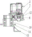
FIG. 3 is a schematic structural view of a front view cross section of a steering engine part according to the present invention;
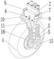
FIG. 4 is a schematic perspective view of the present invention;
in the figure, the steering wheel comprises a chassis 1, a steering engine 2, a hub motor 3, a wheel 5, a hydraulic damping spring shock absorber 6, a support 7, a synchronous pulley I8, a synchronous pulley II 9, a synchronous belt 10, a dead axle 11, a connecting frame 12, a bearing I13, a rotating shaft 14, a bearing II 15, a hub flange 16 and a stabilizer bar.
Detailed Description
The utility model will be further described with reference to fig. 1 to 4.
The utility model provides a four-wheel drive four-turn robot wheel train structure, includes chassis 1, and four edges of its lower extreme are provided with the train respectively, and the train includes: the bracket 6 is arranged on the fixed shaft 10, and the steering engine 2 is arranged on the bracket 6; the fixed shaft 10 is arranged at the lower end of the chassis 1, a through hole is formed in the fixed shaft 10 in the vertical direction, a rotating shaft 13 is rotatably arranged in the through hole through a bearing II 14, and the steering engine 2 drives the rotating shaft 13 to rotate through a transmission mechanism; a connecting frame 11 mounted at the lower end of the rotating shaft 13; the hub flange 15 is positioned at the lower end of the connecting frame 11, a rotating shaft of the hub motor 3 is arranged on the hub flange 15, and the outer ring of the hub motor 3 is provided with a wheel 4; and two hydraulic damping spring shock absorbers 5 which are respectively arranged along the vertical direction, wherein the two hydraulic damping spring shock absorbers 5 are arranged along the front-back direction, the upper ends of the hydraulic damping spring shock absorbers 5 are fixed on the connecting frame 11, and the lower ends of the hydraulic damping spring shock absorbers are installed on the hub flange 15. When the chassis 1 needs to turn, a rotating shaft of a steering engine 2 rotates by a certain angle, the rotating shaft 13 is driven to rotate by a transmission mechanism, the rotating shaft 13 drives two hydraulic damping spring shock absorbers 5 to drive a hub flange 15 to rotate by a connecting piece 11, the wheels 4 are driven to rotate, the weight of a vehicle body is supported by the hydraulic damping spring shock absorbers 5, vibration generated by road bumping is absorbed, and stable running of the robot is kept, a suspension system is connected with the chassis and bears chassis load and external load, the wheels 4 can uniformly land when passing through a concave-convex road surface by the hydraulic damping spring shock absorbers 5, the adhesion force between the tires and the ground is kept, four steering engines 2 are controlled by driving the four hub motors 3, the steering and driving are flexible, and the control technology is simple, the driving and steering power is strong, and the applicable scene of the robot under complex road conditions is expanded, so that different task requirements are met.
The transmission mechanism can be as follows structure, and it includes through I12 rotation of bearing installs synchronous pulley I7 on chassis 1 and coaxial arrangement in the epaxial synchronous pulley II 8 of pivot 13, is connected through hold-in range 9 transmission between I7 of synchronous pulley and the synchronous pulley II 8, and the diameter of synchronous pulley I7 is less than the diameter of synchronous pulley II 8. Steering wheel 2 drive synchronous pulley I7 rotates certain angle, and synchronous pulley I7 passes through synchronous belt 9 drive synchronous pulley II 8 and rotates to realize driving shaft 13 and rotate, because synchronous pulley I7's diameter is less than synchronous pulley II 8, consequently synchronous pulley I7 is connected with synchronous pulley II 8's transmission and is played the effect of speed reduction amplification moment of torsion, can easily drive wheel 4 and rotate.
Preferably, still include stabilizer bar 16, it is the U font structure, and two hydraulic damping spring shock absorbers 5 are fixed mutually with stabilizer bar 16, and stabilizer bar 16's both ends are fixed through threaded connection with the hydraulic damping spring shock absorber 5 of homonymy respectively. The suspension system employs a hydraulic damping spring shock absorber 5, a stabilizer bar 16 to connect the chassis 1 and the wheels 4 together. The stabilizer bar 16 of the suspension system prevents the wheel 4 from being excessively longitudinally tilted when passing through a road block or a depressed road surface, and serves to keep the vehicle body as balanced as possible and to stabilize the vehicle in the longitudinal direction. When the robot crosses an obstacle, the wheels 4 tilt forwards and backwards around the wheel shafts, the front hydraulic damping spring shock absorbers 5 and the rear hydraulic damping spring shock absorbers 5 of the steering mechanism do not jump uniformly, the hydraulic damping spring shock absorbers 5 press to the stabilizer bars, the stabilizer bars 16 are twisted, the elastic force of the rod bodies can prevent the hydraulic damping spring shock absorbers 5 from being lifted, and therefore the two hydraulic damping spring shock absorbers 5 are kept balanced as much as possible, and the function of longitudinal stability is achieved
Finally, it should be noted that: although the present invention has been described in detail with reference to the foregoing embodiments, it will be apparent to those skilled in the art that changes may be made in the embodiments and/or equivalents thereof without departing from the spirit and scope of the utility model. Any modification, equivalent replacement, or improvement made within the spirit and principle of the present invention should be included in the protection scope of the present invention.
Claims (3)
1. The utility model provides a four-wheel drive four-turn robot wheel train structure, includes chassis (1), and four edges of its lower extreme are provided with the train respectively, its characterized in that, the train includes:
the bracket (6) is arranged on the fixed shaft (10), and the steering engine (2) is arranged on the bracket (6);
the steering mechanism comprises a fixed shaft (10) which is arranged at the lower end of a chassis (1), a through hole is formed in the fixed shaft (10) in the vertical direction, a rotating shaft (13) is rotatably arranged in the through hole through a bearing II (14), and a steering engine (2) drives the rotating shaft (13) to rotate through a transmission mechanism;
the connecting frame (11) is arranged at the lower end of the rotating shaft (13);
the hub flange (15) is positioned at the lower end of the connecting frame (11), a rotating shaft of the hub motor (3) is arranged on the hub flange (15), and the outer ring of the hub motor (3) is provided with a wheel (4); and
two hydraulic damping spring shock absorbers (5) are respectively arranged along the vertical direction, the two hydraulic damping spring shock absorbers (5) are arranged along the front-back direction, the upper ends of the hydraulic damping spring shock absorbers (5) are fixed on the connecting frame (11), and the lower ends of the hydraulic damping spring shock absorbers are installed on the hub flange (15).
2. The four-wheel drive four-turn robot gear train structure according to claim 1, wherein: the transmission mechanism comprises a synchronous pulley I (7) which is rotatably arranged on the chassis (1) through a bearing I (12) and a synchronous pulley II (8) which is coaxially arranged on a rotating shaft (13), the synchronous pulley I (7) is in transmission connection with the synchronous pulley II (8) through a synchronous belt (9), and the diameter of the synchronous pulley I (7) is smaller than that of the synchronous pulley II (8).
3. The four-wheel drive four-turn robot gear train structure according to claim 1, wherein: still include stabilizer bar (16), it is U font structure, and two hydraulic damping spring shock absorbers (5) are fixed mutually with stabilizer bar (16), and the both ends of stabilizer bar (16) are fixed through threaded connection with the hydraulic damping spring shock absorber (5) of homonymy respectively.
Priority Applications (1)
| Application Number | Priority Date | Filing Date | Title |
|---|---|---|---|
| CN202122536409.3U CN216185444U (en) | 2021-10-21 | 2021-10-21 | Four-wheel-drive four-rotation robot wheel train structure |
Applications Claiming Priority (1)
| Application Number | Priority Date | Filing Date | Title |
|---|---|---|---|
| CN202122536409.3U CN216185444U (en) | 2021-10-21 | 2021-10-21 | Four-wheel-drive four-rotation robot wheel train structure |
Publications (1)
| Publication Number | Publication Date |
|---|---|
| CN216185444U true CN216185444U (en) | 2022-04-05 |
Family
ID=80886090
Family Applications (1)
| Application Number | Title | Priority Date | Filing Date |
|---|---|---|---|
| CN202122536409.3U Active CN216185444U (en) | 2021-10-21 | 2021-10-21 | Four-wheel-drive four-rotation robot wheel train structure |
Country Status (1)
| Country | Link |
|---|---|
| CN (1) | CN216185444U (en) |
Cited By (8)
| Publication number | Priority date | Publication date | Assignee | Title |
|---|---|---|---|---|
| CN114026998A (en) * | 2021-11-08 | 2022-02-11 | 焦昭源 | Heavy metal soil that can sow and landfill is restoreed and is used seeding equipment |
| CN114954637A (en) * | 2022-06-08 | 2022-08-30 | 中国人民解放军国防科技大学 | Four-rotation four-wheel-drive motion robot |
| CN115593502A (en) * | 2022-10-20 | 2023-01-13 | 山东新一代信息产业技术研究院有限公司(Cn) | A chassis of a mobile robot and its steering method |
| CN115675630A (en) * | 2022-11-22 | 2023-02-03 | 山东新一代信息产业技术研究院有限公司 | Robot hollow planetary gear rotating mechanism and rotation control method |
| CN115675631A (en) * | 2022-11-22 | 2023-02-03 | 山东新一代信息产业技术研究院有限公司 | A four-wheel-drive four-rotation robot steering mechanism and rotation method |
| CN116038722A (en) * | 2022-12-02 | 2023-05-02 | 网易(杭州)网络有限公司 | Massage robot, control method of massage robot, electronic device and medium |
| CN116161118A (en) * | 2023-02-03 | 2023-05-26 | 深圳市人工智能与机器人研究院 | Mobile chassis |
| CN116279907A (en) * | 2023-01-12 | 2023-06-23 | 山东新一代信息产业技术研究院有限公司 | An outdoor robot chassis and its rotation method |
-
2021
- 2021-10-21 CN CN202122536409.3U patent/CN216185444U/en active Active
Cited By (9)
| Publication number | Priority date | Publication date | Assignee | Title |
|---|---|---|---|---|
| CN114026998A (en) * | 2021-11-08 | 2022-02-11 | 焦昭源 | Heavy metal soil that can sow and landfill is restoreed and is used seeding equipment |
| CN114026998B (en) * | 2021-11-08 | 2023-10-27 | 焦昭源 | Can plant seeding and heavy metal soil restoration of landfill is with seeding equipment |
| CN114954637A (en) * | 2022-06-08 | 2022-08-30 | 中国人民解放军国防科技大学 | Four-rotation four-wheel-drive motion robot |
| CN115593502A (en) * | 2022-10-20 | 2023-01-13 | 山东新一代信息产业技术研究院有限公司(Cn) | A chassis of a mobile robot and its steering method |
| CN115675630A (en) * | 2022-11-22 | 2023-02-03 | 山东新一代信息产业技术研究院有限公司 | Robot hollow planetary gear rotating mechanism and rotation control method |
| CN115675631A (en) * | 2022-11-22 | 2023-02-03 | 山东新一代信息产业技术研究院有限公司 | A four-wheel-drive four-rotation robot steering mechanism and rotation method |
| CN116038722A (en) * | 2022-12-02 | 2023-05-02 | 网易(杭州)网络有限公司 | Massage robot, control method of massage robot, electronic device and medium |
| CN116279907A (en) * | 2023-01-12 | 2023-06-23 | 山东新一代信息产业技术研究院有限公司 | An outdoor robot chassis and its rotation method |
| CN116161118A (en) * | 2023-02-03 | 2023-05-26 | 深圳市人工智能与机器人研究院 | Mobile chassis |
Similar Documents
| Publication | Publication Date | Title |
|---|---|---|
| CN216185444U (en) | Four-wheel-drive four-rotation robot wheel train structure | |
| CN110239336A (en) | Chassis system and robot | |
| CN112026910A (en) | Wire-controlled chassis platform applied to unmanned full-freedom steering | |
| WO2022134087A1 (en) | Suspension structure, angle module system and motor vehicle | |
| CN110949498B (en) | An electric vehicle and a wheel hub structure with integrated steering and suspension | |
| CN111619296B (en) | Suspension system for wheel train movement device and automobile | |
| CN112092539B (en) | A mobile chassis | |
| CN101648573A (en) | Automobile traveling mechanism with wheel hub comprehensively drive and turning | |
| CN213862471U (en) | Multi-functional AGV robot | |
| CN113263909A (en) | Four-wheel independent damping, steering and driving wheeled robot chassis | |
| CN110329023B (en) | Double-cross arm independent suspension for hub motor | |
| CN111186270B (en) | Electric wheel independent suspension structure with four control arms | |
| CN213322544U (en) | Active side-tipping system | |
| CN213323321U (en) | Wire-controlled chassis platform applied to unmanned full-freedom steering | |
| CN213501652U (en) | Movable chassis | |
| CN214985620U (en) | Front wheel steering mechanism with damping function for unmanned sweeper and unmanned sweeper | |
| CN212667480U (en) | Steering mechanism of wheeled robot chassis | |
| CN212556585U (en) | Duplex shock absorber, double-upright-column single-swing-arm suspension system and suspension type moving platform | |
| CN213501683U (en) | Chassis with zero turning radius and strong shock resistance | |
| CN219506087U (en) | Robot chassis turns to and damping device | |
| CN116572683B (en) | Independent suspension wheel rim assembly | |
| CN218805455U (en) | Chassis and self-moving equipment | |
| CN219790269U (en) | Electric trailer frame with remote control steering function | |
| CN218112773U (en) | Mobile robot chassis | |
| CN113696998B (en) | Double-column single swing arm suspension mobile platform based on double shock absorber |
Legal Events
| Date | Code | Title | Description |
|---|---|---|---|
| GR01 | Patent grant | ||
| GR01 | Patent grant |