CN216741663U - Cooler with noise reduction structure - Google Patents
Cooler with noise reduction structure Download PDFInfo
- Publication number
- CN216741663U CN216741663U CN202220070187.2U CN202220070187U CN216741663U CN 216741663 U CN216741663 U CN 216741663U CN 202220070187 U CN202220070187 U CN 202220070187U CN 216741663 U CN216741663 U CN 216741663U
- Authority
- CN
- China
- Prior art keywords
- noise reduction
- fixedly connected
- spring
- cooler
- wall
- Prior art date
- Legal status (The legal status is an assumption and is not a legal conclusion. Google has not performed a legal analysis and makes no representation as to the accuracy of the status listed.)
- Active
Links
- 238000013016 damping Methods 0.000 claims abstract description 26
- 230000035939 shock Effects 0.000 claims description 4
- 230000000694 effects Effects 0.000 abstract description 14
- 230000003139 buffering effect Effects 0.000 abstract description 7
- 230000005484 gravity Effects 0.000 abstract description 3
- 230000002035 prolonged effect Effects 0.000 abstract description 2
- 230000006835 compression Effects 0.000 description 2
- 238000007906 compression Methods 0.000 description 2
- 238000001816 cooling Methods 0.000 description 2
- 239000003381 stabilizer Substances 0.000 description 2
- 230000008093 supporting effect Effects 0.000 description 2
- 239000006096 absorbing agent Substances 0.000 description 1
- 230000004048 modification Effects 0.000 description 1
- 238000012986 modification Methods 0.000 description 1
- 239000010705 motor oil Substances 0.000 description 1
Images




Landscapes
- Vibration Prevention Devices (AREA)
Abstract
The utility model relates to the field of coolers, in particular to a cooler with a noise reduction structure, which comprises a cooler body and a noise reduction seat, wherein the bottom of the cooler body is fixedly connected with a fixing column, the inner side wall of the noise reduction seat is provided with a slide way, the inner bottom wall of the slide way is fixedly connected with a second spring, and the top of the second spring is fixedly connected with a lifting rod. According to the utility model, through the connecting block, the noise reduction plate and the third spring, when the cooler body generates larger vibration after working, the downward gravity of the cooler body drives the connecting block to move downwards, so that the top of the noise reduction plate moves downwards, the first spring and the third spring are in a compressed state, the first spring and the third spring play a role in buffering the noise reduction plate, and the cooler body is subjected to a damping effect, so that the device does not generate larger noise during working, the good experience of a user is improved, and the service life of the device is prolonged.
Description
Technical Field
The utility model relates to the technical field of coolers, in particular to a cooler with a noise reduction structure.
Background
The cooler is a necessary cooling component of engineering equipment such as an engine and the like, is mainly used for cooling engine oil, and is of a long strip cooler, a cylindrical cooler and the like, and the cylindrical cooler is common and widely applied in the market at present.
And the current most coolers in the existing market can produce great noise at work due to vibration, so that the user is not good in experience feeling, the original paper of the cooler is influenced, and the service life of the device is further shortened.
Therefore, it is desirable to provide a cooler with a noise reduction structure.
SUMMERY OF THE UTILITY MODEL
In order to solve the problem that the cooler generates large noise due to vibration during operation, the utility model aims to provide the cooler with the noise reduction structure.
The utility model provides a cooler with a noise reduction structure, which comprises a cooler body and a noise reduction seat, wherein the bottom of the cooler body is fixedly connected with a fixed column, the inner side wall of the noise reduction seat is provided with a slide way, the inner bottom wall of the slide way is fixedly connected with a second spring, the top of the second spring is fixedly connected with a lifting rod, the inner bottom wall of the noise reduction seat is provided with a damping groove, and the inner wall of the damping groove is fixedly connected with a telescopic rod.
The utility model discloses a damping groove's shock attenuation, including shock attenuation groove, the top fixedly connected with lifter plate of telescopic link, the first spring of inner diapire fixedly connected with of damping groove, the bottom fixedly connected with connecting block of fixed column, the inner wall of connecting block is inlayed and is had the bearing, the inner circle fixedly connected with dwang of bearing, the fixed surface of dwang is connected with and is fallen the board of making an uproar, fall the one end fixedly connected with slider of the board of making an uproar, one side fixedly connected with third spring of slider.
Preferably, the lifter is "L" type lifter, and the outer wall of lifter and the inner wall sliding connection of slide, and then the lifter can receive the spring action of second spring and receive cushioning effect.
Preferably, the top of the lifting rod penetrates through the noise reduction seat and extends to the outside of the noise reduction seat, the top of the lifting rod is fixedly connected with the bottom of the cooler body, and then the cooler body can be buffered through the lifting rod.
Preferably, first spring cup joints with the telescopic link activity, and the top of first spring and the bottom fixed connection of lifter plate, and then the lifter plate moves down and can receive the reaction force of first spring.
Preferably, one end of the sliding block extends to the inside of the damping groove, the outer wall of the sliding block is connected with the inner wall of the damping groove in a sliding mode, and the sliding block can move in the damping groove.
Preferably, the connecting block is "U" type connecting block of handstand, and the one end of third spring and the inside wall fixed connection of shock attenuation groove, and then the elasticity of third spring can be to falling the board of making an uproar and playing the cushioning effect through the slider.
Preferably, the noise reduction plate is an inclined noise reduction plate, the surface of the noise reduction plate is movably connected with the surface of the lifting plate, and the lifting plate is driven to move downwards when the noise reduction plate rotates.
Preferably, one side of the noise reduction seat is fixedly connected with a support leg, the outer wall of the support leg is fixedly connected with an anti-slip pad, and therefore the supporting effect of the cooler body can be achieved.
The working principle is as follows: when the vibration absorber is operated and used, when the cooler body vibrates during working, the downward force of the fixed column drives the connecting block to move downwards, so that the noise reduction plate rotates, the upper end of the noise reduction plate moves downwards, one end, far away from the connecting block, of the noise reduction plate drives the sliding block to move in the damping groove, a reaction force is given to the noise reduction plate through the elastic force of the third spring and the first spring, a buffering effect is achieved, the vibration amplitude of the cooler body is reduced, and noise reduction is achieved.
The technical means of the utility model can obtain the following technical effects:
(1) according to the utility model, through the connecting block, the noise reduction plate and the third spring, when the cooler body generates larger vibration after working, the downward gravity of the cooler body drives the connecting block to move downwards, so that the top of the noise reduction plate moves downwards, the first spring and the third spring are in a compressed state, the first spring and the third spring play a role in buffering the noise reduction plate, and the cooler body is subjected to a damping effect, so that the device can not generate larger noise during working, the good experience of a user is improved, and the service life of the device is prolonged.
(2) According to the utility model, through the arranged slide way, the second spring and the lifting rod, when the cooler body vibrates and moves downwards, one end of the lifting rod is driven to move downwards in the slide way, so that the second spring is in a compressed state, the elastic force of the second spring has a buffering effect on the lifting rod, and further a secondary damping effect is achieved on the cooler body, thus the noise reduction effect of the device is improved, and the practicability of the device is greatly improved.
Drawings
FIG. 1 is a schematic structural view of the present invention;
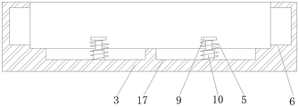
FIG. 2 is a front cross-sectional view of a noise reduction mount of the present invention;
FIG. 3 is a schematic view of the internal structure of the noise reduction base according to the present invention;
FIG. 4 is an enlarged view of the structure of FIG. 2;
fig. 5 is a schematic structural view of the connecting block of the present invention.
In the figure: 1. a cooler body; 2. fixing a column; 3. a noise reduction base; 4. a support leg; 5. a first spring; 6. a slideway; 7. a second spring; 8. a lifting rod; 9. a lifting plate; 10. a telescopic rod; 11. connecting blocks; 12. a bearing; 13. rotating the rod; 14. a noise reduction plate; 15. a slider; 16. a third spring; 17. a damping groove.
Detailed Description
In order to more clearly understand the technical features, objects, and effects of the present invention, embodiments of the present invention will now be described with reference to the accompanying drawings.
Example 1
The preferred embodiment of the cooler with noise reduction structure provided by the present invention is shown in fig. 1 to 5: the utility model provides a cooler with structure of making an uproar falls, includes cooler body 1 and falls the seat of making an uproar 3, and the bottom fixedly connected with fixed column 2 of cooler body 1 falls the inside wall of the seat of making an uproar 3 and has seted up slide 6, the interior diapire fixedly connected with second spring 7 of slide 6, the top fixedly connected with lifter 8 of second spring 7, the interior diapire of the seat of making an uproar 3 of making an uproar falls and has seted up damping groove 17, the inner wall fixedly connected with telescopic link 10 of damping groove 17.
The top of the telescopic rod 10 is fixedly connected with a lifting plate 9, the inner bottom wall of a damping groove 17 is fixedly connected with a first spring 5, the bottom of the fixed column 2 is fixedly connected with a connecting block 11, the inner wall of the connecting block 11 is inlaid with a bearing 12, the inner ring of the bearing 12 is fixedly connected with a rotating rod 13, the surface of the rotating rod 13 is fixedly connected with a noise reduction plate 14, one end of the noise reduction plate 14 is fixedly connected with a sliding block 15, one side of the sliding block 15 is fixedly connected with a third spring 16, through the arranged connecting block 11, the noise reduction plate 14 and the third spring 16, when the cooler body 1 works to generate larger vibration, the downward gravity of the cooler body 1 drives the connecting block 11 to move downwards, and then the top of the noise reduction plate 14 moves downwards, so that the first spring 5 and the third spring 16 are in a compression state, and then the first spring 5 and the third spring 16 play a role of buffering role in the noise reduction plate 14, and then the cooler body 1 is subjected to a damping effect, thereby the device can not produce great noise at the during operation, and then improved the good experience sense that the user used, and then improved the device's life, slide 6 through setting up, second spring 7 and lifter 8, when cooler body 1 takes place vibrations and when the lapse, the one end that drives lifter 8 is in the inside lapse of slide 6, and then second spring 7 is compression state, the elasticity of second spring 7 plays the cushioning effect to lifter 8, and then play secondary absorbing effect to cooler body 1, thereby the noise reduction effect of the device has been improved, very big improvement the device's practicality.
Example 2
On the basis of embodiment 1, a preferred embodiment of a cooler with a noise reduction structure provided by the present invention is shown in fig. 1 to 5: lifter 8 is "L" type lifter, and the outer wall of lifter 8 and the inner wall sliding connection of slide 6, and then lifter 8 can receive the spring action of second spring 7 and receive the cushioning effect.
In this embodiment, the top of the lifting rod 8 penetrates through the noise reduction base 3 and extends to the outside of the noise reduction base 3, and the top of the lifting rod 8 is fixedly connected with the bottom of the cooler body 1, so that the cooler body 1 can receive a buffering effect through the lifting rod 8.
In this embodiment, the first spring 5 is movably sleeved with the telescopic rod 10, and the top of the first spring 5 is fixedly connected with the bottom of the lifting plate 9, so that the lifting plate 9 moves downwards to receive the reaction force of the first spring 5.
In this embodiment, one end of the slider 15 extends to the inside of the damping groove 17, and the outer wall of the slider 15 is connected with the inner wall of the damping groove 17 in a sliding manner, so that the slider 15 can move inside the damping groove 17.
In this embodiment, the connecting block 11 is an inverted U-shaped connecting block, and one end of the third spring 16 is fixedly connected to the inner side wall of the damping groove 17, so that the elastic force of the third spring 16 can damp the noise reduction plate 14 through the slider 15.
In this embodiment, the noise reduction plate 14 is an inclined noise reduction plate, and the surface of the noise reduction plate 14 is movably connected to the surface of the lifting plate 9, so that the noise reduction plate 14 drives the lifting plate 9 to move downward when rotating.
In this embodiment, one side fixedly connected with stabilizer blade 4 of seat 3 of making an uproar falls, and the outer wall fixedly connected with slipmat of stabilizer blade 4, and then can realize the supporting role of cooler body 1.
When the cooler body 1 vibrates during operation and use, as shown in fig. 1 to 5, the downward force of the fixed column 2 drives the connecting block 11 to move downwards, and then the noise reduction plate 14 rotates, so that the upper end of the noise reduction plate 14 moves downwards, and one end, away from the connecting block 11, of the noise reduction plate 14 drives the sliding block 15 to move inside the damping groove 17, and further a reaction force is given to the noise reduction plate 14 through the elastic force action of the third spring 16 and the first spring 5, so that a buffering effect is achieved, the vibration amplitude of the cooler body 1 is reduced, and noise reduction is achieved.
The above description is only an exemplary embodiment of the present invention, and is not intended to limit the scope of the present invention. Any equivalent changes and modifications that can be made by one skilled in the art without departing from the spirit and principles of the utility model should be considered within the scope of the utility model. Moreover, it should be noted that the components of the present invention are not limited to the above-mentioned whole application, and various technical features described in the present specification can be selected to be used alone or in combination according to actual needs, so that the present invention should cover other combinations and specific applications related to the present invention.
Claims (8)
1. A cooler with a noise reduction structure comprises a cooler body (1) and a noise reduction base (3), and is characterized in that: the bottom of the cooler body (1) is fixedly connected with a fixed column (2), the inner side wall of the noise reduction seat (3) is provided with a slide way (6), the inner bottom wall of the slide way (6) is fixedly connected with a second spring (7), the top of the second spring (7) is fixedly connected with a lifting rod (8), the inner bottom wall of the noise reduction seat (3) is provided with a damping groove (17), and the inner wall of the damping groove (17) is fixedly connected with a telescopic rod (10);
the top fixedly connected with lifter plate (9) of telescopic link (10), first spring (5) of interior diapire fixedly connected with of shock attenuation groove (17), bottom fixedly connected with connecting block (11) of fixed column (2), the inner wall of connecting block (11) is inlayed and is had bearing (12), inner circle fixedly connected with dwang (13) of bearing (12), board (14) of making an uproar falls in the fixed surface of dwang (13) is connected with, fall one end fixedly connected with slider (15) of board (14) of making an uproar, one side fixedly connected with third spring (16) of slider (15).
2. A cooler having a noise reducing structure according to claim 1, wherein: the lifting rod (8) is an L-shaped lifting rod, and the outer wall of the lifting rod (8) is connected with the inner wall of the slide way (6) in a sliding mode.
3. A cooler having a noise reducing structure according to claim 1, wherein: the top of the lifting rod (8) penetrates through the noise reduction base (3) and extends to the outside of the noise reduction base (3), and the top of the lifting rod (8) is fixedly connected with the bottom of the cooler body (1).
4. A cooler having a noise reducing structure according to claim 1, wherein: the first spring (5) is movably sleeved with the telescopic rod (10), and the top of the first spring (5) is fixedly connected with the bottom of the lifting plate (9).
5. A cooler having a noise reducing structure according to claim 1, wherein: one end of the sliding block (15) extends to the inside of the damping groove (17), and the outer wall of the sliding block (15) is connected with the inner wall of the damping groove (17) in a sliding mode.
6. A cooler having a noise reducing structure according to claim 1, wherein: the connecting block (11) is an inverted U-shaped connecting block, and one end of the third spring (16) is fixedly connected with the inner side wall of the damping groove (17).
7. A cooler having a noise reducing structure according to claim 1, wherein: the noise reduction plate (14) is an inclined noise reduction plate, and the surface of the noise reduction plate (14) is movably connected with the surface of the lifting plate (9).
8. A cooler having a noise reducing structure according to claim 1, wherein: one side of the noise reduction base (3) is fixedly connected with a support leg (4), and the outer wall of the support leg (4) is fixedly connected with an anti-slip mat.
Priority Applications (1)
| Application Number | Priority Date | Filing Date | Title |
|---|---|---|---|
| CN202220070187.2U CN216741663U (en) | 2022-01-12 | 2022-01-12 | Cooler with noise reduction structure |
Applications Claiming Priority (1)
| Application Number | Priority Date | Filing Date | Title |
|---|---|---|---|
| CN202220070187.2U CN216741663U (en) | 2022-01-12 | 2022-01-12 | Cooler with noise reduction structure |
Publications (1)
| Publication Number | Publication Date |
|---|---|
| CN216741663U true CN216741663U (en) | 2022-06-14 |
Family
ID=81912790
Family Applications (1)
| Application Number | Title | Priority Date | Filing Date |
|---|---|---|---|
| CN202220070187.2U Active CN216741663U (en) | 2022-01-12 | 2022-01-12 | Cooler with noise reduction structure |
Country Status (1)
| Country | Link |
|---|---|
| CN (1) | CN216741663U (en) |
-
2022
- 2022-01-12 CN CN202220070187.2U patent/CN216741663U/en active Active
Similar Documents
| Publication | Publication Date | Title |
|---|---|---|
| CN109516342B (en) | Improved elevator buffer | |
| CN210174603U (en) | Automobile engine shock attenuation installation device | |
| CN219687440U (en) | Damping buffer device for cabin body | |
| KR20100028514A (en) | Shock absorber filled with bead | |
| CN216414064U (en) | Generator base with vibration/noise reduction function | |
| CN216009338U (en) | Embedded steel spring drum-type steel wire rope vibration isolator | |
| CN210935425U (en) | Shock attenuation chemical industry centrifuge | |
| CN210336125U (en) | Take shock-absorbing function's abalone slice processing to use section device | |
| CN211525427U (en) | Elevator host computer damping device | |
| CN217873971U (en) | Noise reduction type compressor base | |
| CN222949209U (en) | A special sleeve for high-strength building shock-absorbing support | |
| CN216145979U (en) | Electric power cabinet base with shock-absorbing function | |
| CN215763017U (en) | Vibration damping base for air compressor | |
| CN221185736U (en) | Vibration damper for vertical numerical control machine tool | |
| CN210231585U (en) | Take shock-absorbing function's rocking arm to bore | |
| CN208041033U (en) | A kind of mechanical equipment damping device of novel improved structure | |
| CN212330327U (en) | Damping and buffering base of machine tool | |
| CN220286817U (en) | Water pump damping device for water conservancy pump station | |
| CN217107850U (en) | Guide rail base with shock-absorbing function | |
| CN217029805U (en) | High-strength damping base for machining | |
| CN215763049U (en) | Pig is slaughtered and uses damping device | |
| CN223104925U (en) | A shock absorbing structure of an oil cylinder | |
| CN110768450A (en) | Vibration/noise reduction's inverter motor | |
| CN206539639U (en) | A kind of damping device for vehicle horizontal shock-absorbing | |
| CN215601440U (en) | Ethernet switch that security is good |
Legal Events
| Date | Code | Title | Description |
|---|---|---|---|
| GR01 | Patent grant | ||
| GR01 | Patent grant |