CN219188773U - Fastener for punching and drilling compound machine convenient to install - Google Patents
Fastener for punching and drilling compound machine convenient to install Download PDFInfo
- Publication number
- CN219188773U CN219188773U CN202223394301.6U CN202223394301U CN219188773U CN 219188773 U CN219188773 U CN 219188773U CN 202223394301 U CN202223394301 U CN 202223394301U CN 219188773 U CN219188773 U CN 219188773U
- Authority
- CN
- China
- Prior art keywords
- wall
- rod
- fastener
- milling cutter
- punching
- Prior art date
- Legal status (The legal status is an assumption and is not a legal conclusion. Google has not performed a legal analysis and makes no representation as to the accuracy of the status listed.)
- Expired - Fee Related
Links
Images


Classifications
-
- Y—GENERAL TAGGING OF NEW TECHNOLOGICAL DEVELOPMENTS; GENERAL TAGGING OF CROSS-SECTIONAL TECHNOLOGIES SPANNING OVER SEVERAL SECTIONS OF THE IPC; TECHNICAL SUBJECTS COVERED BY FORMER USPC CROSS-REFERENCE ART COLLECTIONS [XRACs] AND DIGESTS
- Y02—TECHNOLOGIES OR APPLICATIONS FOR MITIGATION OR ADAPTATION AGAINST CLIMATE CHANGE
- Y02P—CLIMATE CHANGE MITIGATION TECHNOLOGIES IN THE PRODUCTION OR PROCESSING OF GOODS
- Y02P70/00—Climate change mitigation technologies in the production process for final industrial or consumer products
- Y02P70/10—Greenhouse gas [GHG] capture, material saving, heat recovery or other energy efficient measures, e.g. motor control, characterised by manufacturing processes, e.g. for rolling metal or metal working
Landscapes
- Perforating, Stamping-Out Or Severing By Means Other Than Cutting (AREA)
Abstract
本实用新型涉及便于安装的冲钻复合机用紧固件技术领域,且公开了一种便于安装的冲钻复合机用紧固件,包括安装杆;设置在安装杆底部的紧固件组件;设置在安装杆顶部的铣刀安装座;设置在紧固件组件内部的铣刀;以及设置在安装杆内部的传导组件,所述紧固件组件包括安装部,所述安装部的顶部与安装杆的底部固定连接,所述安装部的外壁安装有限位部,所述传导组件包括缓冲部、连接部,铣刀安装座转动带动安装杆转动,安装杆转动通过限位凸条带动移动卡板转动,进而带动连接柱转动,连接柱转动带动十字凸块转动,进而带动铣刀转动,使得铣刀转动过程中的扭矩力传导不经过紧固件组件,减少了紧固件组件受力损坏的概率。

The utility model relates to the technical field of fasteners for punching and drilling compound machines that are easy to install, and discloses a fastener for punching and drilling compound machines that is easy to install, including a mounting rod; a fastener assembly arranged at the bottom of the mounting rod; A milling cutter mounting seat disposed on the top of the mounting rod; a milling cutter disposed inside the fastener assembly; and a conduction assembly disposed inside the mounting rod, the fastener assembly includes a mounting portion, the top of the mounting portion is in contact with the mounting portion The bottom of the rod is fixedly connected, the outer wall of the installation part is equipped with a limiting part, the conductive assembly includes a buffer part and a connecting part, the rotation of the milling cutter mounting seat drives the rotation of the installation rod, and the rotation of the installation rod drives the moving clamp through the limit protrusion Rotation, and then drive the connecting column to rotate, and the rotation of the connecting column drives the rotation of the cross projection, and then drives the rotation of the milling cutter, so that the torque force during the rotation of the milling cutter does not pass through the fastener assembly, reducing the damage to the fastener assembly probability.
Description
技术领域technical field
本实用新型涉及便于安装的冲钻复合机用紧固件技术领域,具体为一种便于安装的冲钻复合机用紧固件The utility model relates to the technical field of fasteners for punching and drilling compound machines that are easy to install, in particular to a fastener for punching and drilling compound machines that is easy to install
背景技术Background technique
冲钻复合机在板材加工中起到至关重要的作用,其中直接工作的铣刀属于消耗型用具,在进行长时间的工作后,工作人员需要进行铣刀的更换工作,目前对于铣刀的拆装多是通过锁帽和筒夹作为紧固件进行的,在此过程中,工作人员多会借助扳手等工具进行,这就存在着一定的局限性,体现出了铣刀拆装的便捷性较差。The punching and drilling machine plays a vital role in sheet metal processing. The milling cutters that work directly are consumable tools. After working for a long time, the staff need to replace the milling cutters. At present, the milling cutters Most of the disassembly and assembly is carried out through lock caps and collets as fasteners. In this process, the staff often use tools such as wrenches to carry out, which has certain limitations, which reflects the convenience of disassembly and assembly of milling cutters. Sex is poor.
实用新型内容Utility model content
本实用新型的目的在于提供了一种便于安装的冲钻复合机用紧固件,解决了上述背景技术中提到的问题。The purpose of the utility model is to provide an easy-to-install fastener for a punching and drilling compound machine, which solves the problems mentioned in the above-mentioned background technology.
为实现上述目的,本实用新型提供如下技术方案:一种便于安装的冲钻复合机用紧固件,包括安装杆;In order to achieve the above purpose, the utility model provides the following technical solutions: a fastener for a punching and drilling compound machine that is easy to install, including a mounting rod;
设置在安装杆底部的紧固件组件;a fastener assembly disposed at the bottom of the mounting bar;
设置在安装杆顶部的铣刀安装座;Milling cutter mounting seat set on the top of the mounting rod;
设置在紧固件组件内部的铣刀;a milling cutter positioned inside the fastener assembly;
以及设置在安装杆内部的传导组件,所述紧固件组件包括安装部,所述安装部的顶部与安装杆的底部固定连接,所述安装部的外壁安装有限位部;所述传导组件包括缓冲部、连接部,所述缓冲部位于安装杆的内部,所述连接部位于缓冲部的下方。And the conduction assembly arranged inside the installation rod, the fastener assembly includes a mounting part, the top of the installation part is fixedly connected to the bottom of the installation rod, and the outer wall of the installation part is equipped with a limiting part; the conduction assembly includes A buffer part and a connection part, the buffer part is located inside the installation rod, and the connection part is located below the buffer part.
优选的,所述安装部包括紧固件本体、定位孔,所述紧固件本体的顶部与安装杆的底部固定连接,所述紧固件本体的内壁卡接有挡板,所述挡板的内部固定安装有定位杆,所述定位杆的两端活动贯穿紧固件本体的外壁,所述定位杆位于紧固件本体内侧外部的一端与定位孔卡接,所述定位杆位于紧固件本体内部的一段外壁套接有一号弹簧,所述一号弹簧的一端与挡板的外壁固定连接,所述一号弹簧的另一端与紧固件本体的内壁固定连接,所述定位孔位于铣刀的外壁上。Preferably, the installation part includes a fastener body and a positioning hole, the top of the fastener body is fixedly connected to the bottom of the installation rod, the inner wall of the fastener body is clamped with a baffle, and the baffle The interior of the fastener body is fixed with a positioning rod, and the two ends of the positioning rod move through the outer wall of the fastener body. A section of the outer wall inside the fastener body is sleeved with a No. 1 spring, one end of the No. 1 spring is fixedly connected to the outer wall of the baffle, and the other end of the No. 1 spring is fixedly connected to the inner wall of the fastener body. The positioning hole is located at on the outer wall of the milling cutter.
优选的,所述限位部包括U型板、连接套,所述U型板的外壁与定位杆位于紧固件本体外侧的一端贴合,所述U型板的朝向连接套的一侧外壁开设有插孔,所述连接套的外壁与紧固件本体的外壁固定连接,所述连接套的内壁卡接有插杆,所述插杆活动贯穿插孔,将连接套内的插杆向下插入,将U型板固定在定位杆的外部,完成对定位杆的限位,避免定位杆被带动转动时,从定位孔内脱落。Preferably, the limiting part includes a U-shaped plate and a connecting sleeve, the outer wall of the U-shaped plate fits with the end of the positioning rod outside the fastener body, and the outer wall of the U-shaped plate facing the connecting sleeve A socket is opened, and the outer wall of the connecting sleeve is fixedly connected with the outer wall of the fastener body. The inner wall of the connecting sleeve is clamped with an insertion rod, and the insertion rod moves through the socket, and the insertion rod in the connecting sleeve is moved toward the Insert down, fix the U-shaped plate on the outside of the positioning rod, complete the limit of the positioning rod, and prevent the positioning rod from falling out of the positioning hole when it is driven to rotate.
优选的,所述缓冲部包括二号弹簧、限位凸条,所述二号弹簧的顶端与安装杆的顶部内壁固定连接,所述二号弹簧的底部固定安装有移动卡板,所述移动卡板的外壁与限位凸条卡接,所述限位凸条的外壁与安装杆的内壁固定连接,通过设置二号弹簧使得移动卡板可以沿限位凸条上下移动,便于安装铣刀。Preferably, the buffer part includes a No. 2 spring and a limit protrusion, the top end of the No. 2 spring is fixedly connected to the top inner wall of the installation rod, and the bottom of the No. 2 spring is fixedly installed with a moving clamp. The outer wall of the clamping plate is clamped with the limiting convex strip, and the outer wall of the limiting convex strip is fixedly connected with the inner wall of the installation rod. By setting the No. 2 spring, the mobile clamping plate can move up and down along the limiting convex strip, which is convenient for installing the milling cutter .
优选的,所述连接部包括连接柱、十字凹槽,所述连接柱的顶部与移动卡板的底部固定连接,所述连接柱的底部固定安装有十字凸块,所述十字凸块与十字凹槽卡接,所述十字凹槽位于铣刀的顶端,通过十字凸块和十字凹槽将铣刀与连接柱连接在一起。Preferably, the connecting part includes a connecting column and a cross groove, the top of the connecting column is fixedly connected with the bottom of the movable clamp, and the bottom of the connecting column is fixedly equipped with a cross protrusion, and the cross protrusion is connected to the cross The groove is clipped, and the cross groove is located at the top of the milling cutter, and the milling cutter and the connecting column are connected together through the cross protrusion and the cross groove.
优选的,所述铣刀的顶端外壁与紧固件本体的内侧外壁贴合,所述铣刀的顶端外壁与安装杆的内壁贴合,使得铣刀在转动过程中不会晃动。Preferably, the top outer wall of the milling cutter is in contact with the inner and outer walls of the fastener body, and the top outer wall of the milling cutter is in contact with the inner wall of the mounting rod, so that the milling cutter does not shake during rotation.
优选的,所述定位杆位于紧固件本体外侧的一段固定安装有拉板,便于拉动定位杆,所述定位孔竖直设置有三个,与缓冲部配合可以调节铣刀在安装杆内的安装深度。Preferably, a section of the positioning rod located outside the fastener body is fixedly equipped with a pull plate, which is convenient for pulling the positioning rod. There are three vertical positioning holes, which can adjust the installation of the milling cutter in the mounting rod by cooperating with the buffer part. depth.
本实用新型提供了一种便于安装的冲钻复合机用紧固件。该便于安装的冲钻复合机用紧固件具备以下有益效果:The utility model provides a fastener for a punching and drilling compound machine which is easy to install. The easy-to-install fastener for a punching and drilling compound machine has the following beneficial effects:
(1)、该便于安装的冲钻复合机用紧固件,将向外拉动定位杆使得定位杆向内的一端缩入紧固件本体内,将铣刀穿过紧固件本体插入安装杆内,使得十字凸块卡入十字凹槽内,松开定位杆,一号弹簧复位,带动挡板复位,进而带动定位杆向内移动,使得定位杆卡入定位孔内,完成对铣刀的安装,将U型板开设有插孔的一侧与连接套贴合,将连接套的插杆向下插入,将U型板固定在定位杆的外部,完成对定位杆的限位,避免定位杆被带动转动时,从定位孔内脱落,无需其他工具即可完成对铣刀的安装;(1) For the easy-to-install fastener for punching and drilling compound machines, pull the positioning rod outward so that the inward end of the positioning rod retracts into the fastener body, and insert the milling cutter through the fastener body into the installation rod Make the cross protrusion snap into the cross groove, loosen the positioning rod, the No. 1 spring resets, drives the baffle to reset, and then drives the positioning rod to move inward, so that the positioning rod snaps into the positioning hole, and completes the positioning of the milling cutter For installation, attach the side of the U-shaped plate with the socket to the connecting sleeve, insert the inserting rod of the connecting sleeve downward, and fix the U-shaped plate on the outside of the positioning rod to complete the limit of the positioning rod and avoid positioning When the rod is driven to rotate, it falls off from the positioning hole, and the milling cutter can be installed without other tools;
(2)、该便于安装的冲钻复合机用紧固件,铣刀安装座转动带动安装杆转动,安装杆转动通过限位凸条带动移动卡板转动,进而带动连接柱转动,连接柱转动带动十字凸块转动,进而带动铣刀转动,使得铣刀转动过程中的扭矩力传导不经过紧固件组件,减少了紧固件组件受力损坏的概率。(2) The fasteners for punching and drilling compound machines that are easy to install, the rotation of the milling cutter mounting seat drives the installation rod to rotate, and the rotation of the installation rod drives the movement clamp to rotate through the limit convex strip, which in turn drives the rotation of the connecting column, and the rotation of the connecting column Drive the cross projection to rotate, and then drive the milling cutter to rotate, so that the torque force during the rotation of the milling cutter does not pass through the fastener component, reducing the probability of the fastener component being damaged by force.
附图说明Description of drawings
图1为本实用新型结构示意图;Fig. 1 is the structural representation of the utility model;
图2为本实用新型铣刀结构示意图;Fig. 2 is a structural schematic diagram of the utility model milling cutter;
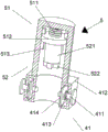
图3为本实用新型安装杆与紧固件本体内部结构示意图;Figure 3 is a schematic diagram of the internal structure of the installation rod and the fastener body of the utility model;
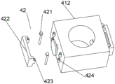
图4为本实用新型限位部爆炸视图结构示意图。Fig. 4 is a structural schematic diagram of an exploded view of the limiting part of the present invention.
图中:1铣刀安装座、2安装杆、3铣刀、4紧固件组件、41安装部、411定位杆、412紧固件本体、413一号弹簧、414挡板、415定位孔、42限位部、421插杆、422U型板、423插孔、424连接套、5传导组件、51缓冲部、511二号弹簧、512移动卡板、513限位凸条、52连接部、521连接柱、522十字凸块、523十字凹槽。In the figure: 1 milling cutter mounting seat, 2 mounting rod, 3 milling cutter, 4 fastener assembly, 41 installation part, 411 positioning rod, 412 fastener body, 413 No. 1 spring, 414 baffle plate, 415 positioning hole, 42 Limiting part, 421 Inserting rod, 422 U-shaped plate, 423 Jack, 424 Connecting sleeve, 5 Conduction component, 51 Buffer part, 511 No. 2 spring, 512 Moving card plate, 513 Limiting convex strip, 52 Connecting part, 521 Connecting post, 522 cross projection, 523 cross groove.
具体实施方式Detailed ways
如图1-4所示,本实用新型提供一种技术方案:一种便于安装的冲钻复合机用紧固件,包括安装杆2;As shown in Figures 1-4, the utility model provides a technical solution: a fastener for a punching and drilling compound machine that is easy to install, including a
设置在安装杆2底部的紧固件组件4;A fastener assembly 4 arranged at the bottom of the
设置在安装杆2顶部的铣刀安装座1;The milling cutter mounting seat 1 arranged on the top of the
设置在紧固件组件4内部的铣刀3;a
以及设置在安装杆2内部的传导组件5,紧固件组件4包括安装部41,安装部41的顶部与安装杆2的底部固定连接,安装部41的外壁安装有限位部42;传导组件5包括缓冲部51、连接部52,缓冲部51位于安装杆2的内部,连接部52位于缓冲部51的下方,安装部41包括紧固件本体412、定位孔415,紧固件本体412的顶部与安装杆2的底部固定连接,紧固件本体412的内壁卡接有挡板414,挡板414的内部固定安装有定位杆411,定位杆411的两端活动贯穿紧固件本体412的外壁,定位杆411位于紧固件本体412内侧外部的一端与定位孔415卡接,定位杆411位于紧固件本体412内部的一段外壁套接有一号弹簧413,一号弹簧413的一端与挡板414的外壁固定连接,一号弹簧413的另一端与紧固件本体412的内壁固定连接,定位孔415位于铣刀3的外壁上,定位杆411位于紧固件本体412外侧的一段固定安装有拉板,便于拉动定位杆411,定位孔415竖直设置有三个,与缓冲部51配合可以调节铣刀3在安装杆2内的安装深度,限位部42包括U型板422、连接套424,U型板422的外壁与定位杆411位于紧固件本体412外侧的一端贴合,U型板422的朝向连接套424的一侧外壁开设有插孔423,连接套424的外壁与紧固件本体412的外壁固定连接,连接套424的内壁卡接有插杆421,插杆421活动贯穿插孔423,将连接套424内的插杆421向下插入,将U型板422固定在定位杆411的外部,完成对定位杆411的限位,避免定位杆411被带动转动时,从定位孔415内脱落,缓冲部51包括二号弹簧511、限位凸条513,二号弹簧511的顶端与安装杆2的顶部内壁固定连接,二号弹簧511的底部固定安装有移动卡板512,移动卡板512的外壁与限位凸条513卡接,限位凸条513的外壁与安装杆2的内壁固定连接,通过设置二号弹簧511使得移动卡板512可以沿限位凸条513上下移动,便于安装铣刀3,连接部52包括连接柱521、十字凹槽523,连接柱521的顶部与移动卡板512的底部固定连接,连接柱521的底部固定安装有十字凸块522,十字凸块522与十字凹槽523卡接,十字凹槽523位于铣刀3的顶端,通过十字凸块522和十字凹槽523将铣刀3与连接柱521连接在一起,铣刀3的顶端外壁与紧固件本体412的内侧外壁贴合,铣刀3的顶端外壁与安装杆2的内壁贴合,使得铣刀3在转动过程中不会晃动。And the conduction assembly 5 arranged inside the
该便于安装的冲钻复合机用紧固件在使用时,将铣刀安装座1安装在冲钻复合机上,向外拉动定位杆411,使得挡板414挤压一号弹簧413,使得定位杆411向内的一端缩入紧固件本体412内,将铣刀3穿过紧固件本体412插入安装杆2内,使得十字凸块522卡入十字凹槽523内,松开定位杆411,一号弹簧413复位,带动挡板414复位,进而带动定位杆411向内移动,使得定位杆411卡入定位孔415内,完成对铣刀3的安装,将U型板422开设有插孔423的一侧与连接套424贴合,将连接套424内的插杆421向下插入,将U型板422固定在定位杆411的外部,完成对定位杆411的限位,避免定位杆411被带动转动时,从定位孔415内脱落,铣刀安装座1转动带动安装杆2转动,安装杆2转动通过限位凸条513带动移动卡板512转动,进而带动连接柱521转动,连接柱521转动带动十字凸块522转动,进而带动铣刀3转动,使得铣刀3转动过程中的扭矩力传导不经过紧固件组件4,减少了紧固件组件4受力损坏的概率。When the fastener for the punch-drill compound machine that is easy to install is in use, the milling cutter mounting seat 1 is installed on the punch-drill compound machine, and the
Claims (7)
Priority Applications (1)
| Application Number | Priority Date | Filing Date | Title |
|---|---|---|---|
| CN202223394301.6U CN219188773U (en) | 2022-12-19 | 2022-12-19 | Fastener for punching and drilling compound machine convenient to install |
Applications Claiming Priority (1)
| Application Number | Priority Date | Filing Date | Title |
|---|---|---|---|
| CN202223394301.6U CN219188773U (en) | 2022-12-19 | 2022-12-19 | Fastener for punching and drilling compound machine convenient to install |
Publications (1)
| Publication Number | Publication Date |
|---|---|
| CN219188773U true CN219188773U (en) | 2023-06-16 |
Family
ID=86724665
Family Applications (1)
| Application Number | Title | Priority Date | Filing Date |
|---|---|---|---|
| CN202223394301.6U Expired - Fee Related CN219188773U (en) | 2022-12-19 | 2022-12-19 | Fastener for punching and drilling compound machine convenient to install |
Country Status (1)
| Country | Link |
|---|---|
| CN (1) | CN219188773U (en) |
-
2022
- 2022-12-19 CN CN202223394301.6U patent/CN219188773U/en not_active Expired - Fee Related
Similar Documents
| Publication | Publication Date | Title |
|---|---|---|
| CN219188773U (en) | Fastener for punching and drilling compound machine convenient to install | |
| CN119115024B (en) | Drilling tool assembly and method of using the same | |
| CN211501256U (en) | High-reliability anti-loosening fastener | |
| CN103522099B (en) | A kind of Rocker arm drilling tool | |
| CN204975405U (en) | Aluminum alloy is perforating device for support | |
| CN218050462U (en) | A portable isometric hole opening tool for metalworking | |
| CN116494281A (en) | Automatic control grabbing device and method for industrial robot | |
| CN212182566U (en) | Wire clamp and wiring fastening assembly thereof | |
| CN213341433U (en) | A single-person operating tool for J-type wire clips | |
| CN212976491U (en) | Pneumatic punching machine | |
| CN223338463U (en) | A cam-type shearing mechanism | |
| CN223656928U (en) | A bushing puller that combines pull-out and hammer-installation functions | |
| CN218693012U (en) | Punching device is used in computer machine case production | |
| CN220739186U (en) | Hollowed-out device for aluminum buckle plate production | |
| CN223099125U (en) | Screw dismounting tool for preventing screw blade from falling off groove | |
| CN219379879U (en) | Front fork punching clamp | |
| CN222141744U (en) | Self-drilling screw with guiding function | |
| CN212495488U (en) | Intelligent lock processing equipment | |
| CN218563413U (en) | Environmental protection door easy to assemble | |
| CN217480414U (en) | Steel structure supporting mechanism convenient to disassemble | |
| CN214922051U (en) | Automatic installation device for positioning pin | |
| CN220967251U (en) | Mop frame with rotary buckle hook structure | |
| CN111590496A (en) | A screw clamping device mounted on a screwdriver | |
| CN214722576U (en) | Automatic installation device for cutter machining | |
| CN214025416U (en) | Positioning mechanism for mounting side wall of auxiliary frame of convection section of ethylene cracking furnace |
Legal Events
| Date | Code | Title | Description |
|---|---|---|---|
| GR01 | Patent grant | ||
| GR01 | Patent grant | ||
| CF01 | Termination of patent right due to non-payment of annual fee | ||
| CF01 | Termination of patent right due to non-payment of annual fee |
Granted publication date: 20230616 |