CN87108398A - Processing method and equipment for daily necessities materials - Google Patents
Processing method and equipment for daily necessities materials Download PDFInfo
- Publication number
- CN87108398A CN87108398A CN87108398A CN87108398A CN87108398A CN 87108398 A CN87108398 A CN 87108398A CN 87108398 A CN87108398 A CN 87108398A CN 87108398 A CN87108398 A CN 87108398A CN 87108398 A CN87108398 A CN 87108398A
- Authority
- CN
- China
- Prior art keywords
- working
- yoke
- tube
- holder
- working element
- Prior art date
- Legal status (The legal status is an assumption and is not a legal conclusion. Google has not performed a legal analysis and makes no representation as to the accuracy of the status listed.)
- Pending
Links
- 239000000463 material Substances 0.000 claims abstract description 169
- 238000012545 processing Methods 0.000 claims abstract description 43
- 238000000034 method Methods 0.000 claims abstract description 11
- 230000008878 coupling Effects 0.000 claims description 41
- 238000010168 coupling process Methods 0.000 claims description 41
- 238000005859 coupling reaction Methods 0.000 claims description 41
- 235000013399 edible fruits Nutrition 0.000 claims description 9
- 239000003814 drug Substances 0.000 claims description 7
- 229940079593 drug Drugs 0.000 claims description 6
- 238000007789 sealing Methods 0.000 claims description 6
- 239000002699 waste material Substances 0.000 claims description 5
- 238000005192 partition Methods 0.000 claims description 4
- 229910001018 Cast iron Inorganic materials 0.000 claims description 3
- 230000009471 action Effects 0.000 claims description 3
- 230000001276 controlling effect Effects 0.000 claims description 3
- 229910052593 corundum Inorganic materials 0.000 claims description 3
- 239000010431 corundum Substances 0.000 claims description 3
- 229910010293 ceramic material Inorganic materials 0.000 claims description 2
- 230000000295 complement effect Effects 0.000 claims description 2
- 230000001105 regulatory effect Effects 0.000 claims description 2
- 230000005540 biological transmission Effects 0.000 claims 1
- 230000015572 biosynthetic process Effects 0.000 claims 1
- 239000011236 particulate material Substances 0.000 claims 1
- 238000003801 milling Methods 0.000 abstract description 18
- 238000000227 grinding Methods 0.000 description 26
- 238000013461 design Methods 0.000 description 9
- 241000196324 Embryophyta Species 0.000 description 8
- 230000008901 benefit Effects 0.000 description 6
- 239000000047 product Substances 0.000 description 5
- 239000000919 ceramic Substances 0.000 description 4
- 230000004048 modification Effects 0.000 description 4
- 238000012986 modification Methods 0.000 description 4
- 239000002002 slurry Substances 0.000 description 4
- 241000219094 Vitaceae Species 0.000 description 3
- 230000008859 change Effects 0.000 description 3
- 235000021021 grapes Nutrition 0.000 description 3
- 239000007787 solid Substances 0.000 description 3
- 239000004575 stone Substances 0.000 description 3
- 229920002522 Wood fibre Polymers 0.000 description 2
- 230000001419 dependent effect Effects 0.000 description 2
- 238000006073 displacement reaction Methods 0.000 description 2
- 235000013305 food Nutrition 0.000 description 2
- 235000011389 fruit/vegetable juice Nutrition 0.000 description 2
- 238000004519 manufacturing process Methods 0.000 description 2
- 239000003921 oil Substances 0.000 description 2
- 239000004033 plastic Substances 0.000 description 2
- 229910052573 porcelain Inorganic materials 0.000 description 2
- 239000002023 wood Substances 0.000 description 2
- OKTJSMMVPCPJKN-UHFFFAOYSA-N Carbon Chemical compound [C] OKTJSMMVPCPJKN-UHFFFAOYSA-N 0.000 description 1
- 241000723382 Corylus Species 0.000 description 1
- 235000007466 Corylus avellana Nutrition 0.000 description 1
- 244000141359 Malus pumila Species 0.000 description 1
- 241000207836 Olea <angiosperm> Species 0.000 description 1
- 244000018633 Prunus armeniaca Species 0.000 description 1
- 235000009827 Prunus armeniaca Nutrition 0.000 description 1
- 244000061456 Solanum tuberosum Species 0.000 description 1
- 235000002595 Solanum tuberosum Nutrition 0.000 description 1
- 238000005299 abrasion Methods 0.000 description 1
- 235000021016 apples Nutrition 0.000 description 1
- 239000011230 binding agent Substances 0.000 description 1
- 239000007795 chemical reaction product Substances 0.000 description 1
- 239000003153 chemical reaction reagent Substances 0.000 description 1
- 235000019219 chocolate Nutrition 0.000 description 1
- 238000010276 construction Methods 0.000 description 1
- 239000000109 continuous material Substances 0.000 description 1
- 230000008021 deposition Effects 0.000 description 1
- 238000011161 development Methods 0.000 description 1
- 238000010586 diagram Methods 0.000 description 1
- 239000000835 fiber Substances 0.000 description 1
- 239000008187 granular material Substances 0.000 description 1
- 239000010439 graphite Substances 0.000 description 1
- 229910002804 graphite Inorganic materials 0.000 description 1
- 238000009434 installation Methods 0.000 description 1
- 239000007788 liquid Substances 0.000 description 1
- 239000012263 liquid product Substances 0.000 description 1
- 239000004579 marble Substances 0.000 description 1
- 239000003973 paint Substances 0.000 description 1
- 239000002245 particle Substances 0.000 description 1
- 230000002093 peripheral effect Effects 0.000 description 1
- 235000012015 potatoes Nutrition 0.000 description 1
- 230000008569 process Effects 0.000 description 1
- 238000006798 ring closing metathesis reaction Methods 0.000 description 1
- 238000010008 shearing Methods 0.000 description 1
- 239000002689 soil Substances 0.000 description 1
- 230000003068 static effect Effects 0.000 description 1
- XLYOFNOQVPJJNP-UHFFFAOYSA-N water Substances O XLYOFNOQVPJJNP-UHFFFAOYSA-N 0.000 description 1
- 238000001238 wet grinding Methods 0.000 description 1
- 239000002025 wood fiber Substances 0.000 description 1
Images


Classifications
-
- B—PERFORMING OPERATIONS; TRANSPORTING
- B02—CRUSHING, PULVERISING, OR DISINTEGRATING; PREPARATORY TREATMENT OF GRAIN FOR MILLING
- B02C—CRUSHING, PULVERISING, OR DISINTEGRATING IN GENERAL; MILLING GRAIN
- B02C7/00—Crushing or disintegrating by disc mills
- B02C7/18—Disc mills specially adapted for grain
-
- B—PERFORMING OPERATIONS; TRANSPORTING
- B02—CRUSHING, PULVERISING, OR DISINTEGRATING; PREPARATORY TREATMENT OF GRAIN FOR MILLING
- B02C—CRUSHING, PULVERISING, OR DISINTEGRATING IN GENERAL; MILLING GRAIN
- B02C7/00—Crushing or disintegrating by disc mills
- B02C7/10—Crushing or disintegrating by disc mills with eccentric discs
-
- B—PERFORMING OPERATIONS; TRANSPORTING
- B02—CRUSHING, PULVERISING, OR DISINTEGRATING; PREPARATORY TREATMENT OF GRAIN FOR MILLING
- B02C—CRUSHING, PULVERISING, OR DISINTEGRATING IN GENERAL; MILLING GRAIN
- B02C7/00—Crushing or disintegrating by disc mills
- B02C7/11—Details
- B02C7/14—Adjusting, applying pressure to, or controlling distance between, discs
Landscapes
- Engineering & Computer Science (AREA)
- Food Science & Technology (AREA)
- Apparatuses For Bulk Treatment Of Fruits And Vegetables And Apparatuses For Preparing Feeds (AREA)
- Meat, Egg Or Seafood Products (AREA)
- Filling Or Emptying Of Bunkers, Hoppers, And Tanks (AREA)
Abstract
A method and a grinding-type apparatus for processing living necessities, which at least utilize two working elements arranged in the machine base to be matched with each other by two end surfaces of opposite surfaces, wherein one of the working elements is directly driven. The processed material is finished in a short processing period at a high processing speed in a cold state, thereby obtaining a refined product of high quality. The milling apparatus is a high-performance apparatus which can be modified in an extremely simple manner according to the particular requirements of use, in order to provide a milling apparatus which is as versatile as possible by means of only one apparatus together with a set of exchangeable apparatus elements.
Description
The invention relates to a method for processing materials of daily necessities and medicines and further for processing waste materials, and to a grinding-type device for carrying out the method, which is operated by at least two working elements on a device base cooperating with each other on the end faces of the opposite faces thereof, and at least one of which is directly driven by a rotary drive.
The use of mill-type equipment for a wide variety of commercial and domestic purposes has led to the development of a wide variety of specialized equipment designs depending on the nature of the particular product and the type of product being processed.
The object of the invention is to provide a high-performance method and a corresponding mill-type plant which is simple in its structural design and operation and provides operational safety and maintenance-free, which can be changed for each specific application to a special simple plant form, using only a few exchangeable plant elements, to provide a multipurpose mill-type plant which serves as a multipurpose plant with the widest possible range of use, which can provide, for example, grain or food milling or oil milling, and also a fruit milling, in particular for stemmed grapes, nut shelling milling, in particular for laboratory milling for finely ground pharmaceuticals, milling for processing various slurries, and finally not unimportably for producing wood fiber pulp from wood chips and at the same time processing both drier products and materials and also products and materials containing moisture, and can be used to treat various liquids added or vice versa, i.e. to separate the various liquid product fractions from the product.
According to the invention, a method for processing materials that are related to living necessities as well as drugs and further applicable waste, whereby specific materials, such as grains, fruits, nuts or drugs, are brought together with their own weight and/or the action of external forces that are transported by at least one rotating material transport device to at least one central material collecting section, with the peripheries of said material collecting sections being as free as possible from turbulence, with said peripheries being brought to a material processing section, which is much smaller than the material collecting section, in which the material is processed at a very high processing speed in a completely cold state within a very short processing time, and whereby optionally the parts of the processed material are separated from each other and discharged separately from the material processing section.
A mill-type plant for carrying out said method, which plant comprises at least two working elements arranged on a machine base and cooperating with facing end surfaces, and one of the at least two elements being directly dragged by a rotary drive, characterized in that: the machine frame, by changing its position, such as by the turning of a part of the machine frame and turning together with the parts and elements of the machine, is adapted to be opened manually in a simple manner for the exchange of the elements of the machine, by means of connecting means which can be repeatedly released and closed, for example by means of a hinge, optionally cooperating with a snap-ring locker, and adapted to be reconnected in a simple manner, so as to form a frame system for working a specific material, which system comprises at least two working elements, each of which is arranged on a holder, said holders being eccentric with respect to each other, and at least one of the two holders being arranged such that it can change its position with respect to the other holder by means of an adjusting device, and one of the two holders having a working element supported thereon being in an idle polished state, the holder simultaneously serves the function of feeding material into a material collecting portion between two working members, which holder is designed as a stationary material feed tube or at least a tube cooperating with the feed tube and being relatively stationary in relation to the holder, both working members being connected to the respective holder in a manner facilitating replacement by means of coupling members, the machine frame being provided with at least one guide member for collecting or separating portions of a particular material according to the requirements of the material, at least one material feed member being provided on the frame, at least one material transport device and one or several material discharge devices being provided selectively for processing the processed material or the discharge of portions of the material according to the requirements of the material to be processed, and wherein at least one rotary drive (9) is provided for the dragging of at least one working member, and a feeding device for a specific material is selectively provided and selectively communicated with the material feeding portion according to the requirements of the material to be processed, and the coupling of the device and a specific rotary driving device is completed by a coupling component.
The advantages obtained by the present invention will be seen firstly in the economical use of the equipment, which can be selectively installed on specific floors when operating at atmospheric pressure in the housing, but also in the more robust design of the equipment housing, with which the processing of materials can be carried out at higher pressures, and with which the working elements can be operated at higher speeds in a particularly short processing time, and with which a high quality can be guaranteed for specific end products.
Furthermore, various additional advantages of the present invention will be shown in further detail below by a description of various figures of various embodiments.
The invention will now be described in more detail, by way of example and without limitation, with reference to various embodiments shown in the accompanying drawings. Wherein:
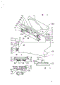
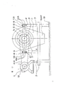
figure 1 is an axial sectional side view showing a mill-type apparatus in a ready-to-operate condition;
FIG. 2 is a side view showing the apparatus of FIG. 1 in a fully open position by pivoting or lifting the yoke or yoke-shaped housing of the apparatus outwardly;
FIGS. 3 and 4 are views showing the releasable attachment portion and its support portion of the working element of the apparatus of FIG. 1;
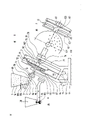
figure 5 is a cross-sectional side view showing a grinding apparatus according to the present invention modified as compared to the embodiment shown in figure 1;
fig. 6 is a diagram showing a further modification of the delivery device in the form of a Roots pump (Roots pump) for material delivery, which may be used in the embodiment of fig. 5,
fig. 7 is a side view showing a main part of the working element shown in fig. 5, which is composed of a brush and a screen, which are in a plan side view in cooperation with each other;
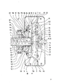
FIG. 8 shows an enlarged view of an embodiment of the apparatus according to FIG. 5, in a vertical axial section through a central part thereof, wherein the difference with respect to FIG. 5 is that the working elements thereof are in the form of a grating disc, for example when applied for grating grains;
FIG. 9 is an axial cross-sectional view showing an embodiment of the apparatus identical to that shown in FIG. 8, but in a cross-sectional view;
FIG. 10 is a view showing a portion of the axial cross-section shown in FIG. 9, but with brushes and screens in place of the grinding disks as working elements;
FIG. 11 is a view showing a portion of a filter used in place of a screen for material processing;
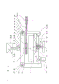
FIG. 12 is a plan view showing the apparatus of FIG. 5 with the rotary drive disposed outside the machine base, and only the V-pulleys thereof shown, and
fig. 13 is a side view showing a view looking in the direction toward the yoke of the device.
In fig. 1, an axial cross-sectional side view of an embodiment of a milling apparatus is shown, in a ready-to-operate state and for carrying out the method according to the invention, the material to be processed being indicated with the reference numeral 1, a transport device for usable material, such as a worm or pump (see in particular fig. 5 and 6) is indicated with 2, a central material collection portion is indicated with 3, the periphery of the collecting section is indicated by 4, the relatively small material processing section by 5, the entire mill-type plant by 6, the machine base is indicated by 7, the working element which is matched with two opposite end surfaces is indicated by 8, the rotary drive means of which is indicated by 9 and the releasable and closable coupling means on the base 7 are indicated by 10 and may comprise a hinge 11 and a buckle-type closure 12 cooperating therewith. Each of the two working members 8 is individually arranged on its holder 13, the two holders 13 being eccentric with respect to each other, one of the at least two holders 13 being arranged such that it can be positionally changed with respect to the other holder 13 by means of an adjusting device 14, and one of the two holders 13 having associated therewith a working member 8 supported thereon in an oscillating state, freely running. The holder 13 is furthermore intended for feeding the material 1 into a material collecting part 3 which is located between the cooperating surfaces of the two working members 8 or into a tube which cooperates with the holder 13 and which is for example part of a material feeding member 18, i.e. designed as a stationary feed tube 15. The essential advantage that can be achieved thereby is that the supply of material is always ensured to be carried out without interruptions even when the working element is operated at high speed. Both working elements 8 can be coupled together in an easily exchangeable manner by means of a coupling element 16 with the holder 13 to which they are connected. This makes it possible to replace or replace the working element simply and quickly for each specific working situation required. Depending on the material 1, the machine frame 7 can optionally be provided with a guide element 17 for collecting or, in particular, for separating parts of the material 1 to be processed. Furthermore, at least one material supply element 18 is arranged on the machine base 7, which supply element is adapted to the material feed device 2, optionally in the form of at least one feed worm 99, in particular to a feed section 112 or a feed pump, for example in the form of a roots pump (see fig. 6, 8 and 9), depending on the material 1 to be processed. The discharge of the material or material portions 1 to be processed is effected by means of one or several material discharge elements 19 arranged below the machine base 7. At least in the disc-shaped working element 8, the part of the central supply opening 60 to be provided in the working element 8 communicating with the material supply tube 15 is provided in the holder 13 or in the material supply tube 15, which opening 60 is enlarged in order to form a central material collecting portion 3, so that a recess-like free space is formed, which extends in radial direction towards the periphery 4 of the working element 8, into a gap-shaped material processing portion 5 between the two end faces 61 of the two working elements 8, which processing portions are mutually opposed. The processing disk 8 (processing element) on the feed side has a substantially annular boundary zone 62 in its material processing portion 5. The axial cross-section of this boundary region 62 is generally convex in vertical central cross-section with respect to the end face 61 of the other working element 8, and thus the boundary region 62 is convex. This region mates with a complementary convex end face 111 of the other working element 8. By means of the device 6, the material 1 can be processed completely under pressure and at high speed by the rotary drive 9, which has the advantage that it can be processed in a particularly cold state in a particularly short time. The material supply element 18 is arranged on a yoke 22 or on a yoke-shaped housing cover 23, which yoke can be pivoted about a hinge 11 serving as a connecting device 10 in accordance with one end or border region 24, whereby the machine base 7 can be opened and closed, and in order to be able to adjust the mutual distance of the end faces 61 of the two working elements 8 in the material processing section 5 appropriately in accordance with the requirements of the material 1 to be processed, the hinge 11 is fastened to an adjusting device 14, which consists of a guide part 25 fastened to the machine base 7 and an adjusting part 27, which adjusting part 27 can be adjusted in the axial direction of the holder 13 on the guide part 25 by means of an adjusting screw 26.
On the other end 28 of the yoke 22, or at another border 29 located opposite the border 24, a hook 30 is provided, which projects outside the machine base 7 and to which a clasp-type closure 12 is coupled, functioning as the coupling device 10, and on one end of which a locking strip 31 of a clasp 32 is provided, which can be repeatedly inserted and released. In order to adapt to the specific adjustment requirements of the adjustment section 27 or to achieve a uniform adjustment of the spatial distance between the two end faces 61, the snap ring holder 33 of the snap ring closure 12 at the other end can be fixed adjustably at the location 36 of the machine base 7 by means of an adjusting screw 35. Since the clasp holder 33 is readjustable in connection with the threaded pin 34, the clasp holder 33 being guided in a sliding sleeve 109 mounted on the aforementioned portion 36 on the machine base 7 and by means of an adjusting screw 35 supported on the sliding sleeve 109, the adjustment of the position of the yoke 22 at one end thereof is carried out by the adjusting device 14 and can be readjusted at the other end thereof by means of the adjusting screw 35 to be adapted to the particular material 1 to be machined, whereby the mutual distance between the end faces 61 of the working elements 8 can be ensured uniformly. The yoke 22 or yoke housing 23 has a central yoke opening 37 for the supply of the particular material 1, through which a feed funnel 38 with a feed funnel tube 39 projects into the yoke 22 or housing 23, said feed funnel 38 acting as the material supply element 18.
The stationary feed hopper tube 39 is concentrically surrounded at a spacing 48 by a tube 40, which tube 40 functions as a swing support 13 and which tube is held at the yoke-side end 41 by a first ring 42. The ring 42 is arranged in a second ring 44 by means of a pin 43 so as to be pivotable about the axis of the pin 43, the ring 44 being pivotably supported on the yoke 22 or on a yoke flange 47 of the housing cover 23 by means of a yoke pin 45 with a yoke pin 46 extending transversely of the shaft. Due to the static tube 39, the centrifugal force acting on the tube 40 is unlikely to act on the tube 39, and even when the tube 40 is rotated largely at a high speed, the tube 39 used as the supply material 1 causes clogging of the tube 39 due to deposition of the supplied material 1 on the inner wall of the tube 39.
At least one sealing ring 89, in particular a lip-shaped sealing ring, is provided between the feed hopper tube 39 and the tube 40 concentrically surrounding the tube 39, whereby the particular material 1 to be processed can also be supplied at a pressure above atmospheric pressure, and a continuous material supply can be ensured also in the case of high rotational speeds of the tube 40, in which case the material to be processed is completely cold and the processed material can be separated into individual parts and finally discharged.
Corresponding to the first working element 8, such as a first grinding pan and brush, are coupled to the free end 49 of the tube 40, while the tube 40 is supported by means of a coupling element 16 whose design is a plug-in and release element 50 and by means of which it can be freely rotated, swiveled, i.e. swiveled.
On the opposite end face of the first working element 8, a second working element 8, for example a second grinding disc, is arranged, which is suitable for being driven by a rotary drive 9, for example an electric motor, with a freely adjustable distance 51 between the end faces of the two working elements 8, depending on the requirements of the material to be processed.
The second working member 8 is arranged in the machine frame 7 or is arranged by a foundation of the frame, in a generally inclined position with respect to the ground 120, with the axis 52 of the second working member 8 having a parallel and eccentric position with respect to the axis 53 of the feed hopper tube 39 and with respect to the first working member 8. The second working element 8 passes over the stop cam 54, which also acts as the coupling element 16 and is drawn by means of a releasable coupling 86 of the rotor plate 55 of a drive device 9, the rotor plate 55 carrying this working element 8 also being designed as a coupling part 20 and, in addition, being accommodated in a housing compartment 57 on an intermediate side wall 56 of the machine housing 7. The coupling element 16, which allows rapid exchange of the working element 8, ensures a simple construction.
Between the intermediate side wall 56 at one end and the working element 8 at the other end, a collecting tray 58 for the processed material 1 is arranged, which collects the material below the working element 8 and has at least one outlet 59 as a discharge element 19 for the material.
The part of the particular working element 8 which is subject to wear as a result of processing the particular material 1 is held at the part 81 facing the holder 13 by the holder 82 at the part 81 facing the holder 13 by a cup-shaped holder 82, is releasably coupled to the part 81 by a stop cam 54 acting as a coupling element 16 and forms, as part of the holder 82 or its holding plate 84, a coupling member 20 for the particular holder 13 for the rotor plate 55 or rib star 87 (ribstar). The first working element 8, which is arranged at the free end 49 of the tube 40, is directly attached to the tube 40 or to the coupling part 20 on the tube 40, in particular by means of an element 50 mounted on the end 49 and adapted to be resiliently latched to the boundary of the working element 8 and releasable therefrom, whereby it is possible to easily slide on and secure to the tube 40 and to remove it from the tube in an advantageous condition. It is also possible to provide a coupling element 16 associated with them between the portion 81 at one end and the cup-shaped holder 82 at the other end and to provide a positive engagement between the portions 81 and 82 in the manner of a fixed cam 122, so that no relative movement occurs between the rotating working element 8 and the parts 81 and 82. By means of the cup-shaped flange 113 of the holder 82, it is ensured, and in the case of high rotational speeds of the working element 8 and thus centrifugal forces, that at least the portion 81 or the portion 114 subject to wear is held together. The material supply unit 18, such as the feed hopper 69, typically includes an adjustable metering element 104 for controlling or adjusting the amount of the particular material being processed, with at least one actuating element 105 being associated with the metering element 104.
Fig. 2 shows the embodiment of fig. 1 in an almost complete side view, with the equipment base 7 shown in its open position, when the fork arms 22 are lifted from the side. The reference numerals of the components of the apparatus already shown in fig. 1 are also denoted by the same reference numerals in fig. 2. The yoke 22 is shown in a raised position at the border area 29 with the hook 30, while the adjustment device 14 is in a pivoted position about the hinge 11. Reference numeral 43 denotes one of two pins with which the first ring 42 holding the tube 40 is arranged in the second ring 44 so as to be rotatable about the common axis of the two pins 43. By means of the above-mentioned fork arm pin 45 with the transversely extending fork arm pin shaft 46, the second ring 44 can be pivoted by means of the fork arm flange 47 and thus the first working element 8 is supported in a pivotable or pivotable state.
Fig. 3 shows a detailed illustration of an example of a releasable connection of a pivotable holder 13 in the form of a tube 40 with a first working element 8 (as shown in fig. 1). The free end 49 of the tube 40 has one or more resilient latching and release elements 50 which act as coupling elements 16 which latch onto the coupling elements 20 on the first working element 8 and thereby hold the working element 8 in a fixed position and remain fixed when the element 8 is in a rotated condition.
As a modification of the example according to fig. 3, fig. 4 is also a detailed view showing an embodiment of the releasable coupling between the swivel plates 55 with the second working member 8 at one end and the swivel drive means 9 at the other end. The second working element 8 comprises a cup-shaped holder or socket 82 which holds the part 114 of the working element 8 which is subjected to wear by working the specific material 1 to the portion 81 facing the holder 13. The holder 82 is therefore provided with stop cams 86 which project through the rotor plate 55 acting as coupling members 20 and which are held in grooves 116 provided in the projecting free end 115 of said rotor plate 55 and are coupled in the grooves 116 by means of a pivotable locking member 117. The specific locking member 117 is fitted around a locking bolt 118 on the rotor plate 55, and the locking bolt 118 clamps the locking member 117 in a pivotable state. These locking parts are also shown in an enlarged view in a sectional side view and a top view in fig. 4. Various variants of releasable attachment of the holder 13 with the working element 8 are described in the following examples.
The working element 8 has the basic design of a plate or a brush, which is optionally associated with at least one sieve and/or a filter screen. The disk has at least a portion with a roughened end surface portion and is made of cast iron or a ceramic material. The end faces 61 of the working elements 8 are provided with radial or concentric ribs, which face each other as mutually cooperating surfaces, depending on the requirements of the material 1 to be worked, said ribs also being arranged in groups staggered with respect to each other.
Figure 5 is a cross-sectional side view showing a modification of the embodiment of the mill-type apparatus shown in figure 1. Those parts in fig. 5 which correspond to those in fig. 1 and fig. 2 to 4 are denoted by the same reference numerals. The material to be processed is again indicated by the reference numeral 1, a material conveying device is indicated by the reference numeral 2 and is provided with a conveying worm 99 adapted to be activated by means of a drive 9 or conveyed by means of a conveying pump 100 (see fig. 6), the central material collecting portion is indicated by the reference numeral 3, the periphery of which is indicated by the reference numeral 4, the relatively small material processing portion is between the first and second working elements 8, i.e. between the brushes and the at least one screen, is indicated by the reference numeral 5, the milling apparatus as a whole is still indicated by the reference numeral 6, and the apparatus stand surrounding the two working elements 8 is indicated by the reference numeral 7. The equipment base 7 is clamped by a base support bracket 21. At each of the above-mentioned portions 63 and 64 of the bracket 21 (see in detail fig. 13), which are in mutually opposite positions, there is provided a flange fork for each bolt 60, which fork serves to clamp the yoke 22. By removing one of the bolts 68, the yoke 22 can be pivoted about the other bolt 68 on one of its two ends 24 and 28, respectively, which provides the possibility of replacing or replacing the working element 8 in particular in a simple manner.
The material supply element 18 in the form of a feed funnel 69 is provided with an angled or curved feed funnel tube 70 together with the metering element 104 and the actuating element 105 arranged therein. This pipe 70 is separated by a coupling device consisting of a pipe coupling flange 71 mounted on the side of the funnel and a pipe flange 72 mounted on the side of the yoke 22, in other words by the two flanges 71, 72 being fixedly connected to the yoke 22. The pipe portion 119 of the feed hopper pipe 72 is flanged with the pipe coupling flange 70 on the side of the yoke, which pipe portion projects through the yoke 22 and is firmly connected thereto, while at the same time forming the holder 13 for the driven working element 8 in the brush-specific configuration, wherein the pipe portion 119 carries a support bearing 73 which surrounds the pipe portion 119 and acts as a V-pulley 74, as well as the brush 8 dragged over the V-pulley 74. The brush 8 has a central feed opening 60 communicating with the pipe portion 119 for feeding the specific material to be processed into the material collecting portion 3. By means of an additional holder 13 in the form of a shaft 75 fixed to the frame carrier 21, at least one sieve 8 cooperating with the brush 8 is guided at the free end 76 of the shaft 75 in a swinging or swiveling, freely rotating state. The centerlines 78 and 77 of the first and second holders 13, as viewed in space, are parallel to each other and are in an off-center position with respect to each other.
The contact planes 90 of the two facing end faces 61 of the working element 8 are in almost the same position, and the inner space 91 of the equipment housing 7 is divided for separate reception of parts of the specific material 1 to be processed, such as on the one hand fruit stones or stones and on the other hand fruit pulp, by means of a separate guide element 17 formed by a replaceable, double- sided separating wall 92 and 93. Thereby forming two bins 94 and 95 each having an outlet 96 and 97 for functioning as a material discharge element 19.
The housing support bracket 21 of the mill-like equipment 6 has an inclined position with respect to the floor 120 so that the portions of the processed specific material 1 to be collected separately can be automatically discharged by their own weight from the bins 94 and 94 through the outlets 96 and 97 and can be sent to another utilization side.
In order to change the position of one holder 13 of the screen 8 relative to the holder 13 of the other brush 8, in the embodiment shown in fig. 1, adjustment means 14 and readjustment means 108 are provided, which are used in cooperation and allow automatic readjustment of the adjustment means 14.
Fig. 6 shows a modification of the material feed device 2 in the form of a roots pump 100. This pump is disposed in the feed hopper tube 70 to replace the conveying worm 99 and enables rapid feeding of the processing material. As in the embodiment shown in fig. 1, the material supply unit 18 may be constituted by a supply funnel 38 or by a material collection container or the like (not shown) to which the pump 100 is connected via a pipe arrangement.
Fig. 7 shows essentially a side view of the working elements 8 consisting of a brush 8 and the sieve 8 associated with it, these working elements 8 being shown roughly in fig. 5. In addition, the screen 8 is only partially shown in a top view. As with the grinding disc shown in fig. 1, the brush 8 is clamped in a cup-shaped holder or socket 82, the central feed opening of which is indicated by reference numeral 60 and the angstrom-shaped free space of which is indicated by reference numeral 103. The sifter screen 8 used in conjunction with the brush 8 is held by a carrier 83 by a support ring 85, the support ring 85 being releasably connected to a rib star (rib star) or star-shaped rib arrangement 87 which supports the ring 85. As can be seen in the plan view of the screen 8, the holes and perforations therein, which function as part of the material being processed, if the slurry is a pass-through, indicated at 121.
Fig. 8 is an enlarged view showing the central part of the apparatus according to fig. 5, and an axial sectional side view is shown in fig. 8, which differs from that shown in fig. 5 in that the working elements 8 are constituted by grinding discs, which are used when they are used, for example, for grinding grain.
The work document in the form of a grating disk 8 is drawn by means of a rotary drive 9 via a V-pulley 74 using a V-belt 101 as coupling part 20, by means of a support bearing 73, around a pipe part 119 flanged to a feed hopper pipe 70 by means of couplings 71, 72, while the pipe 70 functions as a stationary support 13 for the rotating grating disk 8. Thus, the driven V-pulley 74 is rotated by means of the support bearing 73 about the holder 13 or tube portion 119 together with the rib star 87 dragged by the pulley 84. The ribs 87 are releasably connected to the cup-shaped holder 82 as described above in connection with the design of the rotor plate 55. The part of the wearing part 114 on the grinding disc 8 facing the holder 13 is again indicated with 81. The holder 82 still carries the stop cams 86 which serve as coupling elements 16 which, by virtue of the dragged rib star 87, project as coupling parts 20, in which state the free end 115 of each cam 86 projects with its groove 116 beyond the position of the rib star 87, and the locking parts 117 attached to the cams 86 are mounted on the rib star 87 so as to be pivotable about a locking bolt 118 and, by virtue of the pivoting latch, are inserted into the groove 116 of the nearer stop cam 86, whereby the grinding disc 8 is releasably latched into the rib star 87, and in this way it is possible to simply replace or replace another working element. Also with this loose design, the holder 82 can be provided with a fixed cam 112 for definitive attachment to the portion 81 of the wear part 114 of the grinding disc 8, which portion 81 faces the cup-shaped holder 82.
An idle grinding disc 8, which cooperates with a grinding disc 8 dragged by a driving device 9, has a structure substantially identical to that of the dragged grinding disc 8. A major difference is that the rib 87 of the grinding disc 8, which is rotated by the driven grinding disc 8 in its centre 88 by frictional force exerted on it, is supported on a swingable cup 79 in a cup bearing 80 on a side facing the holder 13. The first grinding pan 8 is located opposite the driven second grinding pan 8 and is guided in rotation with said second grinding pan 8 by an additional holder 13 in the form of a shaft 75, while the shaft 75 is fixed with its free end 76 to the housing support bracket 21, in which case the shaft 75 can rotate freely in a swinging or swiveling manner, wherein the rounded and recessed free end 76 of the shaft 75 engages in a swinging cup 79 and thus forms a fixed abutment for the swinging cup 79 by means of an engaging wedge provided between the parts 76 and 79.
The working element or grinding disc 8 is surrounded by the machine frame 7. Sealing rings 89 are provided between the stand 7 and the dragged rib star 84 and the fixed shaft 75, and also between the driven grinding disc 8 and the fixed pipe portion 119, so that the apparatus 6 can operate under an internal pressure higher than atmospheric pressure. As already shown in fig. 5, the machine base 7 is separated by a two- way partition wall 92 and 93, one part 92 of which is fixed inside the stationary base 7 and the other part 93 is fixed to the idle grinding pan 8 or its rib star 87, and the two parts 92 and 93 are arranged so as to overlap each other slightly, the distance of the overlapping parts being provided between the two parts. A bearing seal 123 is disposed between the backup bearing 73 and the driven rib star 84.
Other components in fig. 8 are still given the same reference numerals as the corresponding components in the above figures. The specific material 1 to be processed is fed in through a stationary pipe section 119 which functions as a material feeding device 2 and enters the material collecting section 3 through a central feed opening 61 communicating with said pipe section 119 and processing takes place by centrifugal force at the high rotational speed of the grinding disc 8 onto the periphery of the collecting section, following which the material collecting section 3 in the material processing section 5 is subjected to a process-dependent (operation-dependent) dislocation between the driven grinding disc 8 on the one hand and the grinding disc 8 rotating with it by frictional engagement over the material 1 to be processed on the other hand.
In the case of a granular material 1, an inclination of about 30 ° with respect to the ground 120 is sufficient. So that the conveyor worm 99 can be rotated by the inflowing material 1 by their impact on the conveying section 112, which conveying section 112 is the end of the conveyor worm 91 in the region of the central feed opening 61 or the material collecting section 3, and the inflow or feeding of the material 1 is thus intensified. In the case of partly thinner material 1 or material 1 being reworked, it is appropriate to increase the above-mentioned inclination angle, in order to ensure that the material 1 has a continuous flow. In the case of large particles of material 1, such as grapes, a drive device 9, such as an electric motor, can be arranged to operate at the free end of the conveyor 99, so that the material 1 can also be fed vertically into the conveyor worm 99. The material conveyor section 112 has a generally sickle-shaped semi-spiral shape with a layer of plastic material applied to at least the two free ends of the section.
In order to maintain a desired adjustment distance 51 between the first and second working members 8, i.e. between the facing end faces of the idle disk 8 and the driven disk 8, any irregularities in the distance can be compensated in an automatically calibrated manner by means of the idle disk 8 or the oscillating support of the disk 8 in the following condition due to the wobble, even when there is a momentary difference in distribution of the material 1 between the just mentioned end faces 61, and even when the relative position between these two end faces 61 has been adjusted or readjusted, which constitutes a considerable advantage of the invention, since, for example, the nuts, seeds or stones are not ground, and thus do not cause taste damage.
Fig. 9 is a view showing an axial section through the embodiment of the apparatus shown in fig. 8, but is a view showing a vertical section of fig. 8. In both figures, the reference numerals used in relation to the corresponding parts are the same as those used in the figures above. Fig. 9 clearly shows that the two holders 13 are arranged parallel to one another and are eccentric, i.e. the freely rotating or idle disk 8 mounted thereon with the tube part 119 on the one hand and the fixed shaft 75 on the other is supported in a swinging manner. Thus, the centre line 78 of the first holder 13 or shaft 75, as seen in the axial sectional view of fig. 9, is in a parallel and eccentric position with respect to the centre line 77 of the second holder 13 or tube portion 119.
The uniformity of the above-mentioned distance 51 between the two opposing end faces 61 of the driven disc 8 on the one hand and the idle disc 8 on the other hand is considerably improved in terms of the return to the original state of the eccentric position between the two holders 13 by the swinging holder of the idle disc 8. Two disks 8 having different diameters and rotations move past each other at different peripheral speeds at almost the same transport speed. A dislocation occurs between the driven disk 8 as one side and the idle disk 8 as the other side, which can tear the material. In the case of a radial or coaxial rib arrangement, in particular also in a group arrangement, shearing of the material to be machined takes place when the distance 51 between the two facing end faces 61 is adjusted accordingly, as a result of the rotation of the two cooperating end faces 61 being a concomitant necessary change in the angle of intersection with the ribs, as a result of the instantaneous oscillating movement from the associated disk 8 and as a result of the relative displacement between the two end faces of the two disks 8 with respect to one another as a result of eccentricity. The processing of the material 1, as in the case described above, ensures a specific quality profile of the processed material in the case of very short cold processing of the material, which is only possible with existing installations at low rotational speeds of the working elements.
Figure 10 is a section of one axial cross-section showing the embodiment of figure 9 but with brushes and screens in place of the work discs. Parts corresponding to those shown in the above figures are still denoted by the same reference numerals. The working element 8 in the form of a brush comprises a support body 124 made of plastic and serves to hold the bristles 125. The contact surfaces 90 of the two working elements 8 or their facing end surfaces 61 are formed by the free ends of the bristles on the one hand and a sieve 8 on the other hand, which is held by a carrier 83 by means of a support ring 85, the support ring 85 being fastened to the circumference of the rib star 87 by means of releasable fastening means 86, such as screws.
Fig. 11 shows a part of an embodiment of a working element 8 which, instead of being composed of a sieve, is composed of a filter net or filter body 126 arranged between two grids 127 and 128, wherein the grid 127 in contact with the brush 8 is of a fine mesh design and the other grid 128 is of a coarse or wide mesh design. The fine mesh grid 127 protects the filter mesh 126 from abrasion during processing of the material 1 and is held together with the filter mesh 126 by supporting the wide mesh grid 128, the latter grid 128 facilitating a faster passage of the filtered material 1.
The apparatus 6 according to the invention can be provided for grain milling or feed milling and for comminution and fine grinding with ribbed working disks of cast iron or ceramic oxide, when marble, graphite or ceramic oxide or porcelain plates are used for milling the green paint and food, when porcelain and ceramic oxide plates are used for milling oils of olives and other oily fruits, when used in milling for shelling of roasted hazelnuts or apricot pits in the chocolate industry using bristled working discs, for the purpose of removing the stems of grapes for wine production, the working plate is also provided with bristles, and for the purpose of utilizing the processed wood shavings as waste, for the manufacture of wood fibre pulp, corundum working disks are used, which, when laboratory milling is used for the milling of drugs and reagents, and when the fruit grinder is used for grinding and milling fruits; ceramic work plates of different nature are used when making fruit pulp and juice.
The embodiment with a rotating filter screen is well suited for squeezing juice from prune pulp and for making mashed apples and potatoes. A particular advantage worth emphasizing in this connection is the continuous feed of material to the filter screen and the continuous discharge of solid matter. Furthermore, the rotating filter screen is suitable for removing binders and water from waste fibre pulp or dewatering from slurry, whereby the particulate solid matter is used as improved soil. In addition to the applications listed above, the apparatus of the invention can also be used very well for wet milling, for thin slurries and very concentrated pastes which have to be milled under very high pressure.
Due to the fact that the particular material 1 being processed is fed through a stationary hollow holder 13 or at least through a feed tube 15 which is relatively stationary with respect to the holder 13, and due to the fact that it is solid in the system of the apparatus 6 in the region from the material feed member 18 to the material discharge member 19, it is also possible to mill under pressure or force through the apparatus 6 when the material 1 is subjected to wet processing.
Fig. 12 is a top plan view showing the apparatus of fig. 5, wherein the rotational drive means 9 of the apparatus 6 is arranged outside the apparatus 6, which is only indicated by its V-shaped pulley 129. The same reference numerals have been used here for the individual components already shown in the above figures and for the corresponding components in the explanation of the above figures. The adjustment of the free gap 106 between the two opposite end faces 61 of the working element 8 can be carried out by means of the shaft 75 fixed by the machine support bracket 21 by means of an adjusting device 14 arranged on the bracket 21 in the direction of the shaft 75 and by means of an adjusting hand wheel 131 in the form of an adjusting yoke 130. The adjusted fixing is achieved by a fixing lever 110. Like the yoke 22 shown in fig. 1, the adjusting yoke 130 is also pivotably supported at its one end 132 and is clamped at its other end by an adjusting element 131 of the readjusting device 108, so that its position can be changed.
The automatic readjustment of the adjusting device 14 or the adjusting yoke 130 is effected by means of the adjusting or regulating element 108, the function of which is to generate an effective pressure between the two working elements 8 and depending on the particular material 1 being processed, wherein the yoke 130 is also subjected to a slight displacement by means of the adjusting element 108, the position of which is variable in dependence on the pressure, for example by means of a pressure relief valve, so that the yoke 130 can be pivoted in a corresponding manner.
In the various embodiments of the apparatus 6 described above, a metering element 104 has an actuating portion 105, such as a pivotable or deflectable gate, which may be disposed within the material feed element 18, such as the feed hopper 38 or 69, for controlling or adjusting the feed of the particular material 1 being processed. The adjustment of the metering element 104 is mainly based on the size of the flow of material through the device 6.
Fig. 13 is a side view of the last embodiment of the display device 6, seen in the direction of the yoke 22 or 130. In fig. 13, the same reference numerals are used for the parts corresponding to those described above. The machine base support bracket 21 secures the machine base 7 in a position inclined with respect to the ground, while at the same time forming a single-sided support for the rotary drive 9 arranged outside the machine base 7 and driving the working element 8. By means of the drive 9 being supported in an inclined state, the V-belt 101, which functions as the coupling element 20, is kept tensioned by the action of the drive 9 and thus the coupling of the V-pulley 74 to the support bearing of the V-pulley 129 with the drive 9 is ensured.
Claims (10)
1. A method for processing material (1) relating to living necessities as well as drugs and further applicable waste, characterized in that a specific material (1), such as grain, fruit, nut or drug, is brought to at least one central material collecting section (3) by its own weight and/or by the action of external forces conveyed by at least one rotating material conveying device (2) as free as possible from turbulence, exerting centrifugal forces uninterruptedly on the periphery (4) of said material collecting section (3), merging with said periphery (4) into a material processing section (5) which is much smaller than the material collecting section (3), in which processing section (5) the material (1) is processed at a very high processing speed in a completely cold state within a very short processing time and, optionally, separating parts of the processed material (1) from each other, and are discharged separately from the material processing section.
2. A mill-type plant (6) for carrying out the method according to claim 1, which plant employs at least two working elements (8) which are arranged on a plant frame (7) and cooperate with their facing end faces, and at least one of which is directly entrained by a rotary drive (9), characterized in that: the machine frame (7), by changing its position, such as by pivoting a part of the machine frame (7) and pivoting together with the parts and elements of the machine, is adapted to be opened manually in a simple manner for the exchange of the elements of the machine, by means of connecting means (10) which can be released and closed repeatedly, for example by means of a flap (11), optionally cooperating with a snap-ring lock (12) and adapted to be reconnected in a simple manner, so as to form a frame system (7) for processing a specific material (1), which system comprises at least two working elements (8), each of which is arranged on a holder (13), said holders (13) being eccentric with respect to each other, and at least one of the two holders (13) being arranged such that it can be changed in its position with respect to the other holder (13) by means of an adjusting device (14), and one of the two supports (13) is to have a working element (8) supported thereon in an idle polished state, the support (13) simultaneously serving to feed material into the material collecting portion (3) between the two working elements, the support being designed as a stationary material feed tube (15) or at least a tube cooperating with the feed tube and being relatively stationary with respect to the support (13), both working elements (8) being connected to the respective support (13) in a manner facilitating replacement by means of a coupling element (16), the machine frame (7) being provided with at least one guide element (17) for collecting or separating portions of a particular material (1) according to the requirements of the material (1), at least one material feed element (18) already provided on the frame (7) according to the requirements of the material (1) to be processed, at least one material conveying device (2) and one or several material discharge devices (19) are optionally provided for the discharge of the processed material or material portions (1), and at least one rotary drive (9) is provided for the drawing of at least one working element (8), and the conveying device (2) for a specific material is optionally provided and optionally communicates with the material conveying portion in accordance with the material requirements to be processed, the coupling of the device (8, 2) to the specific rotary drive (9) being effected by means of a coupling element (20).
3. The apparatus (6) of claim 2, wherein: at least in the case of a working element (8) which is arranged on the holder (13) or on the material supply tube (15) and which is in the form of a working disc or brush, the central supply opening (60) in the working element (8) is enlarged at its location which communicates with the material supply tube (15) to form a central material collecting portion (3) and to form a substantially concave free space (103) which extends in its radial direction towards the periphery (5) of the working element (8) and flows into a void-shaped material processing portion (5) which is located between the two end faces (61) of the two working elements (8) which face one another.
4. The apparatus (6) of claim 2, wherein: at least one working element (8) in the form of a working disc on the feed side has, in its material processing portion (5), a substantially circular annular boundary area (62) which, when viewed in axial cross-section, has a generally convex vertical central cross-section (110) relative to the facing end face (61) of the other working element (8), so that the boundary area having a convex shape cooperates with a complementary concave end face (111) of the other working element (8).
5. The apparatus (6) of claim 2, wherein: the working elements (8) are designed as two working discs or brushes and at least one sieve with an optional filter screen.
6. A device (6) as claimed in any one of claims 2 to 5, characterized in that: the working element (8), such as a working disk, is made of cast iron or a ceramic material and at least a part of it has at least a rough end face, especially when a corundum working disk is used.
7. The apparatus (6) of claim 2, wherein: a yoke (22) or a yoke-shaped housing cover (23) covering the housing is arranged on the device housing (7) or on the housing-holding bracket (21) in the region of the material-feeding element (18), the yoke (22) or the yoke-shaped housing cover (23) being arranged at one end of the device housing (7) or at a boundary region (24) in such a way as to be pivotable about a hinge (11) serving as the connecting means (10), the hinge (11) being fastened to an adjusting device (14) consisting of a guide part (25) fastened to the device housing (7) and an adjusting part (27), which adjusting part (27) is adjustable in the axial direction of the holder (13) by means of an adjusting screw (26), a hook (30) being fastened to the other end (28) of the yoke (22) or to another boundary region (29) located opposite said boundary region (24), which extends outside the machine frame (7) and which is coupled to a guide pin (34) by means of a clasp-type closure (12) functioning as a connecting device (10) with a repeatedly insertable and releasable clasp (31) of its clasp (32), and a clasp holder (33) for the clasp-type closure (12) which is guided in a slide (109) mounted at a portion (36) of the machine frame (7) and which is adapted to be readjusted by means of a screw (35) supported on said slide (109), the yoke (22) or the frame cover (23) having a central yoke opening (37) for the supply of the particulate material (1), a supply funnel (38) functioning as a material supply element (18) extending with its supply funnel tube (39) through the opening (37) and the yoke (22) or the frame cover (23), a pipe (40) which acts as a swing support (13) and concentrically surrounds the stationary feed hopper pipe (39) at a spacing (48) is clamped by means of a first ring (42) which is fastened by means of a pin (43) in a second ring (44) so as to be pivotable about the axis of said pin (43) in such a way that the latter is held pivotably in relation to said ring (44) by means of a yoke pin (45) with a yoke pin shaft (46) arranged perpendicularly to the above-mentioned axis, by means of a yoke (22) or a yoke flange (47) of the base housing (23), at least one sealing ring (89), in particular a lip-shaped sealing ring, being arranged between the feed hopper pipe (39) on the one hand and the pipe (40) concentrically surrounding said feed hopper pipe (39) on the other hand, a first specific working element (8), such as a first working disk or brush, which is coupled to the pipe (40) by means of a coupling element (16) via the free end (49) of the pipe (40), which coupling element (16) is designed as a resilient, latchably insertable and releasable element (50) and is thereby pivotably, i.e. rotatably freely rotatably supported, and at an adjustable distance (51) from the end face of the first working element (8) a second working element (8), such as a second working disk, is arranged, which is adapted to be dragged by means of a rotary drive (9), such as an electric motor, and which second working disk is arranged on the machine frame (7) or is mounted on the basis of a frame which is at an angle of inclination to the ground (120), with respect to the axis (52) of the second working element (8), in a parallel eccentric position with respect to the axis (53) of the feed hopper tube (39) and with respect to the first working element (8), for the second working member (8) to be adapted to be dragged via a stop cam (54) acting as coupling member (16), and the stop cam is used as a part of a transmission plate (55) of the driving device (9), the pivoting plate (55) is designed as a coupling part (20) which supports the second working element (8) and is arranged on a central partition (56) in a housing (57) of the machine housing (7), and wherein a collecting tray (58) for the processed material (1) is arranged between the first and second working elements (8) on the one hand and the intermediate partition wall (56) on the other hand, the collecting tray collects the material under the working element (8) and is provided with a guide element (17) having at least one outlet (59) serving as a material discharge element (19).
8. The apparatus (6) of claim 2, wherein: in two pairs of face portions (63) and (64) of a housing support bracket (21) surrounding the periphery of the equipment housing, each side being provided with a flange yoke (65), guide holes (67) being formed at both ends (66) of the yoke, the holes being arranged in a line for receiving a bolt (68) respectively and clamping the yoke arms (22) to the ends (24) and (28) thereof by means of the bolts, a feed hopper (69) functioning as a material supply member (18) being firmly connected to the yoke arms (22) by means of angled feed hopper tubes (70) thereof via a coupling consisting of tube coupling flanges (71) and (72) on one side of the hopper and on one side of the yoke arms, the tube coupling flange (72) projecting through the yoke arms (22) for the tube portions (119) of the feed hopper tubes (70) being flanged thereto, while said flange (72) is simultaneously solidly connected to said yoke (22), and for the V-shaped pulley (74) and the second working member (8), a support bearing (73), such as a second working disc entrained by the pulley (74), is arranged between the yoke (22) on the one hand and the equipment base (7) surrounding at least the second working member (8) on the other, and on a stationary pipe portion (119) acting as a support (13) and rotatable about the stationary pipe portion (119), and for said second working member (8) there is a central feed opening (60) communicating with the pipe (70) or the pipe portion (119) for feeding the specific material (1) to be processed into the material collection portion (3), the first working member (8), such as a first working disc, by means of an additional support in the form of a shaft (75) fixed by the machine base support bracket (21) (13) Mounted on the free end (76) of the shaft (75) opposite said second working element (8) so as to be guided in a swinging, i.e. revolving, freely rotating condition with parallel eccentric positions in space with respect to the centre lines (77) and (78) of said second and first holders (13), the second working element (8) being guided by a swinging cup (79) provided on the rounded and recessed free end (76) of the shaft (75) and being in an idle condition by means of a cup-shaped bearing (80) rotatable thereabout, the wearing parts of the working elements (8), such as the working disc, the corundum disc, or the brush and the sieve or sieve, being subjected to wear during the processing of the particular material (1), which is provided in a cup-shaped holder (82) or carrier (83) in the holder (13), At the opposite part (81), at least on the support plate (84) of the cup-shaped holder (82) of the support ring (85) of the carrier (83) of the sifter and/or sieve, at the parts thereof facing the specific holder (13), by means of a stop cam (54) acting as a coupling element (16) or by means of a support ring (85) with releasable connecting means (86) together with the carrier (83) to each rib star (87) which acts as a coupling part (20), and in the case of the second working element (8) at its center (88) there is arranged a pipe part (119) of the feed hopper pipe (70) and a cup bearing (80) together with a pivotable cup (79), between the driven rib star (87) on the machine base (7) on the one hand and the driven rib star (87) on the second working element (8) and the fixed axis (75) of the first working element (8) on the other hand, furthermore, between the second working element (8), such as a driven second working disk, on the one hand and the tube section (119) on the other hand, a sealing ring (89) is provided, at least one guide element (17) is provided at approximately the same location, for example at the contact surface (90) of the end faces (61) of the opposite faces of the two working elements (8), which element divides the interior space (91) of the machine frame (7) for the separate collection of the processed, piece-specific material (1) and which element is in a replaceable form, at least two separate partitions (92, 93) for the formation of the bins (94, 95), while each of the two bins (94, 95) has at least one second and one third outlet (96, 97) serving as a material discharge element (19). In the straight portion (98) of the feed hopper tube (70) or in the flange-mounted tube portion (119) there is provided a conveyor worm (99) which functions as a material conveying device (2) for conveying the material to be processed to the working element (8), and in particular has a conveying portion (12), or there is provided a conveying pump (100), such as a roots pump, for which the conveyor worm (99) or the conveying pump (100) is adapted to be dragged by means of a rotary drive (9), the machine base support bracket (21) holding the machine base (7) being generally at an oblique angle relative to the ground (120), while forming a single-sided support for the rotary drive (9), which is arranged outside the machine base (7) and which drags a working element (8) coupled with a V-pulley (74), a V-belt (101) is used for driving the second working element (8), which V-belt acts as a coupling part (20) and is held in a tensioned state by a drive (9), and wherein at least one of the facing end faces (61) of the two working elements (8) has at its central region (102), for example at the central feed opening (60), at least one hollow-shaped free space (103) for forming a material collection part (3) for the specific material (1) to be processed.
9. The apparatus (6) of claim 2, wherein: the material supply element (18), such as the feed hopper (69), is provided with an adjustable metering element (104) for controlling or regulating the supply of the particular material (1) to be processed, the metering element (104) having an actuating element (105).
10. The apparatus (6) of claim 2, wherein: in order to adjust the free gap (106) between the two facing end faces (61) of the two working elements (8), an adjusting device (14) in the form of an adjusting yoke (130) is provided, which is mounted on the machine base support bracket (21) and is adjusted by means of an adjusting hand wheel adapted to be fixed by means of a fixing lever (107), a device (108) being optionally provided for the adjusting device (14) for automatic readjustment of the adjusting device (14).
Applications Claiming Priority (2)
| Application Number | Priority Date | Filing Date | Title |
|---|---|---|---|
| CH05038/86 | 1986-12-17 | ||
| CH503886 | 1986-12-17 |
Publications (1)
| Publication Number | Publication Date |
|---|---|
| CN87108398A true CN87108398A (en) | 1988-06-29 |
Family
ID=4286894
Family Applications (1)
| Application Number | Title | Priority Date | Filing Date |
|---|---|---|---|
| CN87108398A Pending CN87108398A (en) | 1986-12-17 | 1987-12-17 | Processing method and equipment for daily necessities materials |
Country Status (3)
| Country | Link |
|---|---|
| EP (1) | EP0274697A3 (en) |
| CN (1) | CN87108398A (en) |
| WO (1) | WO1988004577A1 (en) |
Cited By (5)
| Publication number | Priority date | Publication date | Assignee | Title |
|---|---|---|---|---|
| CN102440304A (en) * | 2010-10-12 | 2012-05-09 | 梁文涟 | Underlying power eccentric type green tea milling machine |
| CN103100471A (en) * | 2011-11-11 | 2013-05-15 | 吴进驻 | Emulsification grinding device |
| CN108160202A (en) * | 2017-12-25 | 2018-06-15 | 胡自然 | A kind of food grinder for having the function of to adjust grinding thickness |
| CN111744646A (en) * | 2020-07-13 | 2020-10-09 | 马鞍山盛禾新智能科技有限公司 | A multi-angle stationary hydraulic crusher |
| CN112028099A (en) * | 2020-08-20 | 2020-12-04 | 楚祯劼 | Clean production process for preparing polyaluminum chloride from fly ash |
Families Citing this family (3)
| Publication number | Priority date | Publication date | Assignee | Title |
|---|---|---|---|---|
| RU2140324C1 (en) * | 1998-04-06 | 1999-10-27 | Радкевич Николай Александрович | Disc mill |
| FR2786112B1 (en) * | 1998-11-19 | 2001-02-02 | Pierre Lecocq | DEVICE FOR GRINDING CEREALS AND INSTALLATION COMPRISING SUCH DEVICES |
| RU2403976C1 (en) * | 2009-07-15 | 2010-11-20 | Совместное предприятие в форме закрытого акционерного общества "Изготовление, внедрение, сервис" | Disk mill |
Family Cites Families (8)
| Publication number | Priority date | Publication date | Assignee | Title |
|---|---|---|---|---|
| DE21928C (en) * | A. LAACKE in Göppingen | Innovation in disk mills | ||
| DE31081C (en) * | j R. SETZ und J. SCHWEITER in Clus bei Bals- ; thal, Schweiz | Disc mill for grains | ||
| DE249825C (en) * | ||||
| GB402848A (en) * | 1932-06-14 | 1933-12-14 | Eiji Satake | Method of treating kaoliang |
| CH200357A (en) * | 1937-11-15 | 1938-10-15 | Gentilli Ing Paolo | Machine for fine mixing of different, roughly premixed, powdery, dry or moist substances. |
| CH289137A (en) * | 1951-03-21 | 1953-02-28 | Hoffmann Max | Vertical attritor. |
| US2959363A (en) * | 1956-01-06 | 1960-11-08 | James G Rimmer | Portable grinding mill |
| US4257564A (en) * | 1979-08-09 | 1981-03-24 | Pamplin James B | Apparatus and method for crushing material |
-
1987
- 1987-12-16 EP EP87118662A patent/EP0274697A3/en not_active Withdrawn
- 1987-12-16 WO PCT/EP1987/000784 patent/WO1988004577A1/en not_active Ceased
- 1987-12-17 CN CN87108398A patent/CN87108398A/en active Pending
Cited By (8)
| Publication number | Priority date | Publication date | Assignee | Title |
|---|---|---|---|---|
| CN102440304A (en) * | 2010-10-12 | 2012-05-09 | 梁文涟 | Underlying power eccentric type green tea milling machine |
| CN102440304B (en) * | 2010-10-12 | 2013-08-28 | 梁文涟 | Underlying power eccentric type green tea milling machine |
| CN103100471A (en) * | 2011-11-11 | 2013-05-15 | 吴进驻 | Emulsification grinding device |
| CN103100471B (en) * | 2011-11-11 | 2015-04-22 | 吴进驻 | Emulsification grinding device |
| CN108160202A (en) * | 2017-12-25 | 2018-06-15 | 胡自然 | A kind of food grinder for having the function of to adjust grinding thickness |
| CN108160202B (en) * | 2017-12-25 | 2019-07-23 | 浙江金恩食品科技股份有限公司 | A kind of food grinder with adjusting grinding thickness function |
| CN111744646A (en) * | 2020-07-13 | 2020-10-09 | 马鞍山盛禾新智能科技有限公司 | A multi-angle stationary hydraulic crusher |
| CN112028099A (en) * | 2020-08-20 | 2020-12-04 | 楚祯劼 | Clean production process for preparing polyaluminum chloride from fly ash |
Also Published As
| Publication number | Publication date |
|---|---|
| EP0274697A2 (en) | 1988-07-20 |
| EP0274697A3 (en) | 1988-08-03 |
| WO1988004577A1 (en) | 1988-06-30 |
Similar Documents
| Publication | Publication Date | Title |
|---|---|---|
| EP0427504A2 (en) | Grain husking and polishing machine | |
| CN1064863C (en) | Granular material processing apparatus | |
| DE2947758A1 (en) | DEVICE FOR GRINDING CORES | |
| CN87108398A (en) | Processing method and equipment for daily necessities materials | |
| CN115971498B (en) | Pulverizer with multistage grinding function | |
| CN112427085A (en) | A grind selection by winnowing integration processingequipment for cosmetics production | |
| CN211915513U (en) | Metal powder grinding device is used in carbide production | |
| CH645038A5 (en) | CRUSHING PROCESS AND CRUSHER FOR IMPLEMENTING THE PROCESS. | |
| US4767070A (en) | Grinder for use in grinding apparatus | |
| US293047A (en) | Milling apparatus | |
| CN220310505U (en) | Grinder for coating processing | |
| CN113600273B (en) | Grind machine of ceramic raw materials | |
| CN215694688U (en) | Multistage scattering and grading treatment device for cement processing | |
| CN211914453U (en) | Automatic change slag powder sieve separator | |
| CN222778131U (en) | Buckwheat grinding equipment | |
| CN114602589A (en) | A crushing device for aggregate production | |
| CN106984382A (en) | A kind of tomato pomace seed peel separator | |
| CN113002123A (en) | Non-woven fabric sheet flower and grass interlayer processing device | |
| CN213254742U (en) | Stifled device is prevented in zirconium silicate ejection of compact | |
| CN220803591U (en) | Grinder for coating processing | |
| CN221558967U (en) | Sand machine with impurity filtering function | |
| CN222342955U (en) | Graded grinding device for processing compound premix | |
| KR102573750B1 (en) | Corn crushing and sorting device with improved crushing efficiency | |
| CN219988055U (en) | Concrete stirring device | |
| CN220276852U (en) | Granulation machine for preparing chlorphenesin |
Legal Events
| Date | Code | Title | Description |
|---|---|---|---|
| C06 | Publication | ||
| PB01 | Publication | ||
| WD01 | Invention patent application deemed withdrawn after publication |