DE102023211971A1 - Electrode for an electrode/separator arrangement in a battery cell and method for producing such an electrode - Google Patents
Electrode for an electrode/separator arrangement in a battery cell and method for producing such an electrode Download PDFInfo
- Publication number
- DE102023211971A1 DE102023211971A1 DE102023211971.4A DE102023211971A DE102023211971A1 DE 102023211971 A1 DE102023211971 A1 DE 102023211971A1 DE 102023211971 A DE102023211971 A DE 102023211971A DE 102023211971 A1 DE102023211971 A1 DE 102023211971A1
- Authority
- DE
- Germany
- Prior art keywords
- electrode
- active material
- substrate
- substrate film
- material layer
- Prior art date
- Legal status (The legal status is an assumption and is not a legal conclusion. Google has not performed a legal analysis and makes no representation as to the accuracy of the status listed.)
- Granted
Links
Images

Classifications
-
- H—ELECTRICITY
- H01—ELECTRIC ELEMENTS
- H01M—PROCESSES OR MEANS, e.g. BATTERIES, FOR THE DIRECT CONVERSION OF CHEMICAL ENERGY INTO ELECTRICAL ENERGY
- H01M4/00—Electrodes
- H01M4/02—Electrodes composed of, or comprising, active material
- H01M4/13—Electrodes for accumulators with non-aqueous electrolyte, e.g. for lithium-accumulators; Processes of manufacture thereof
-
- H—ELECTRICITY
- H01—ELECTRIC ELEMENTS
- H01M—PROCESSES OR MEANS, e.g. BATTERIES, FOR THE DIRECT CONVERSION OF CHEMICAL ENERGY INTO ELECTRICAL ENERGY
- H01M10/00—Secondary cells; Manufacture thereof
- H01M10/05—Accumulators with non-aqueous electrolyte
- H01M10/052—Li-accumulators
- H01M10/0525—Rocking-chair batteries, i.e. batteries with lithium insertion or intercalation in both electrodes; Lithium-ion batteries
-
- H—ELECTRICITY
- H01—ELECTRIC ELEMENTS
- H01M—PROCESSES OR MEANS, e.g. BATTERIES, FOR THE DIRECT CONVERSION OF CHEMICAL ENERGY INTO ELECTRICAL ENERGY
- H01M4/00—Electrodes
- H01M4/02—Electrodes composed of, or comprising, active material
- H01M4/04—Processes of manufacture in general
- H01M4/0402—Methods of deposition of the material
- H01M4/0404—Methods of deposition of the material by coating on electrode collectors
-
- H—ELECTRICITY
- H01—ELECTRIC ELEMENTS
- H01M—PROCESSES OR MEANS, e.g. BATTERIES, FOR THE DIRECT CONVERSION OF CHEMICAL ENERGY INTO ELECTRICAL ENERGY
- H01M4/00—Electrodes
- H01M4/02—Electrodes composed of, or comprising, active material
- H01M4/04—Processes of manufacture in general
- H01M4/043—Processes of manufacture in general involving compressing or compaction
- H01M4/0435—Rolling or calendering
-
- H—ELECTRICITY
- H01—ELECTRIC ELEMENTS
- H01M—PROCESSES OR MEANS, e.g. BATTERIES, FOR THE DIRECT CONVERSION OF CHEMICAL ENERGY INTO ELECTRICAL ENERGY
- H01M4/00—Electrodes
- H01M4/02—Electrodes composed of, or comprising, active material
- H01M4/04—Processes of manufacture in general
- H01M4/0471—Processes of manufacture in general involving thermal treatment, e.g. firing, sintering, backing particulate active material, thermal decomposition, pyrolysis
-
- H—ELECTRICITY
- H01—ELECTRIC ELEMENTS
- H01M—PROCESSES OR MEANS, e.g. BATTERIES, FOR THE DIRECT CONVERSION OF CHEMICAL ENERGY INTO ELECTRICAL ENERGY
- H01M4/00—Electrodes
- H01M4/02—Electrodes composed of, or comprising, active material
- H01M4/13—Electrodes for accumulators with non-aqueous electrolyte, e.g. for lithium-accumulators; Processes of manufacture thereof
- H01M4/131—Electrodes based on mixed oxides or hydroxides, or on mixtures of oxides or hydroxides, e.g. LiCoOx
-
- H—ELECTRICITY
- H01—ELECTRIC ELEMENTS
- H01M—PROCESSES OR MEANS, e.g. BATTERIES, FOR THE DIRECT CONVERSION OF CHEMICAL ENERGY INTO ELECTRICAL ENERGY
- H01M4/00—Electrodes
- H01M4/02—Electrodes composed of, or comprising, active material
- H01M4/13—Electrodes for accumulators with non-aqueous electrolyte, e.g. for lithium-accumulators; Processes of manufacture thereof
- H01M4/139—Processes of manufacture
-
- H—ELECTRICITY
- H01—ELECTRIC ELEMENTS
- H01M—PROCESSES OR MEANS, e.g. BATTERIES, FOR THE DIRECT CONVERSION OF CHEMICAL ENERGY INTO ELECTRICAL ENERGY
- H01M4/00—Electrodes
- H01M4/02—Electrodes composed of, or comprising, active material
- H01M4/13—Electrodes for accumulators with non-aqueous electrolyte, e.g. for lithium-accumulators; Processes of manufacture thereof
- H01M4/139—Processes of manufacture
- H01M4/1391—Processes of manufacture of electrodes based on mixed oxides or hydroxides, or on mixtures of oxides or hydroxides, e.g. LiCoOx
-
- H—ELECTRICITY
- H01—ELECTRIC ELEMENTS
- H01M—PROCESSES OR MEANS, e.g. BATTERIES, FOR THE DIRECT CONVERSION OF CHEMICAL ENERGY INTO ELECTRICAL ENERGY
- H01M4/00—Electrodes
- H01M4/02—Electrodes composed of, or comprising, active material
- H01M4/13—Electrodes for accumulators with non-aqueous electrolyte, e.g. for lithium-accumulators; Processes of manufacture thereof
- H01M4/139—Processes of manufacture
- H01M4/1393—Processes of manufacture of electrodes based on carbonaceous material, e.g. graphite-intercalation compounds or CFx
-
- H—ELECTRICITY
- H01—ELECTRIC ELEMENTS
- H01M—PROCESSES OR MEANS, e.g. BATTERIES, FOR THE DIRECT CONVERSION OF CHEMICAL ENERGY INTO ELECTRICAL ENERGY
- H01M4/00—Electrodes
- H01M4/02—Electrodes composed of, or comprising, active material
- H01M4/36—Selection of substances as active materials, active masses, active liquids
- H01M4/48—Selection of substances as active materials, active masses, active liquids of inorganic oxides or hydroxides
- H01M4/50—Selection of substances as active materials, active masses, active liquids of inorganic oxides or hydroxides of manganese
- H01M4/505—Selection of substances as active materials, active masses, active liquids of inorganic oxides or hydroxides of manganese of mixed oxides or hydroxides containing manganese for inserting or intercalating light metals, e.g. LiMn2O4 or LiMn2OxFy
-
- H—ELECTRICITY
- H01—ELECTRIC ELEMENTS
- H01M—PROCESSES OR MEANS, e.g. BATTERIES, FOR THE DIRECT CONVERSION OF CHEMICAL ENERGY INTO ELECTRICAL ENERGY
- H01M4/00—Electrodes
- H01M4/02—Electrodes composed of, or comprising, active material
- H01M4/36—Selection of substances as active materials, active masses, active liquids
- H01M4/48—Selection of substances as active materials, active masses, active liquids of inorganic oxides or hydroxides
- H01M4/52—Selection of substances as active materials, active masses, active liquids of inorganic oxides or hydroxides of nickel, cobalt or iron
- H01M4/525—Selection of substances as active materials, active masses, active liquids of inorganic oxides or hydroxides of nickel, cobalt or iron of mixed oxides or hydroxides containing iron, cobalt or nickel for inserting or intercalating light metals, e.g. LiNiO2, LiCoO2 or LiCoOxFy
-
- H—ELECTRICITY
- H01—ELECTRIC ELEMENTS
- H01M—PROCESSES OR MEANS, e.g. BATTERIES, FOR THE DIRECT CONVERSION OF CHEMICAL ENERGY INTO ELECTRICAL ENERGY
- H01M4/00—Electrodes
- H01M4/02—Electrodes composed of, or comprising, active material
- H01M4/36—Selection of substances as active materials, active masses, active liquids
- H01M4/58—Selection of substances as active materials, active masses, active liquids of inorganic compounds other than oxides or hydroxides, e.g. sulfides, selenides, tellurides, halogenides or LiCoFy; of polyanionic structures, e.g. phosphates, silicates or borates
- H01M4/583—Carbonaceous material, e.g. graphite-intercalation compounds or CFx
- H01M4/587—Carbonaceous material, e.g. graphite-intercalation compounds or CFx for inserting or intercalating light metals
-
- H—ELECTRICITY
- H01—ELECTRIC ELEMENTS
- H01M—PROCESSES OR MEANS, e.g. BATTERIES, FOR THE DIRECT CONVERSION OF CHEMICAL ENERGY INTO ELECTRICAL ENERGY
- H01M4/00—Electrodes
- H01M4/02—Electrodes composed of, or comprising, active material
- H01M4/64—Carriers or collectors
- H01M4/66—Selection of materials
- H01M4/663—Selection of materials containing carbon or carbonaceous materials as conductive part, e.g. graphite, carbon fibres
-
- H—ELECTRICITY
- H01—ELECTRIC ELEMENTS
- H01M—PROCESSES OR MEANS, e.g. BATTERIES, FOR THE DIRECT CONVERSION OF CHEMICAL ENERGY INTO ELECTRICAL ENERGY
- H01M4/00—Electrodes
- H01M4/02—Electrodes composed of, or comprising, active material
- H01M4/64—Carriers or collectors
- H01M4/66—Selection of materials
- H01M4/668—Composites of electroconductive material and synthetic resins
-
- Y—GENERAL TAGGING OF NEW TECHNOLOGICAL DEVELOPMENTS; GENERAL TAGGING OF CROSS-SECTIONAL TECHNOLOGIES SPANNING OVER SEVERAL SECTIONS OF THE IPC; TECHNICAL SUBJECTS COVERED BY FORMER USPC CROSS-REFERENCE ART COLLECTIONS [XRACs] AND DIGESTS
- Y02—TECHNOLOGIES OR APPLICATIONS FOR MITIGATION OR ADAPTATION AGAINST CLIMATE CHANGE
- Y02E—REDUCTION OF GREENHOUSE GAS [GHG] EMISSIONS, RELATED TO ENERGY GENERATION, TRANSMISSION OR DISTRIBUTION
- Y02E60/00—Enabling technologies; Technologies with a potential or indirect contribution to GHG emissions mitigation
- Y02E60/10—Energy storage using batteries
Landscapes
- Chemical & Material Sciences (AREA)
- Engineering & Computer Science (AREA)
- Chemical Kinetics & Catalysis (AREA)
- Electrochemistry (AREA)
- General Chemical & Material Sciences (AREA)
- Materials Engineering (AREA)
- Manufacturing & Machinery (AREA)
- Inorganic Chemistry (AREA)
- Composite Materials (AREA)
- Battery Electrode And Active Subsutance (AREA)
- Cell Electrode Carriers And Collectors (AREA)
Abstract
Die Erfindung betrifft eine Elektrode für eine Elektroden-/Separator-Anordnung (3) in einer Batteriezelle, insbesondere Lithiumionen-Batteriezelle, mit einer Substratfolie (5), die ein- oder beidseitig mit einer Aktivmaterialschicht (7) beschichtet ist. Erfindungsgemäß ist die Substratfolie (5) aus leitfähigem Graphit (17) und einem Binder (15), insbesondere PTFE, gebildet.The invention relates to an electrode for an electrode/separator assembly (3) in a battery cell, in particular a lithium-ion battery cell, comprising a substrate film (5) coated on one or both sides with an active material layer (7). According to the invention, the substrate film (5) is formed from conductive graphite (17) and a binder (15), in particular PTFE.
Description
Die Erfindung betrifft eine Elektrode für eine Elektroden-/Separator-Anordnung in einer Batteriezelle nach dem Oberbegriff des Anspruches 1, ein Verfahren zur Fertigung einer solchen Elektrode nach dem Oberbegriff des Anspruches 8 sowie eine Batteriezelle nach dem Oberbegriff des Anspruches 9.The invention relates to an electrode for an electrode/separator arrangement in a battery cell according to the preamble of
Eine gattungsgemäße Elektrode weist eine Substratfolie auf, die ein- oder beidseitig mit einer Aktivmaterialschicht beschichtet ist. Bei einer solchen Elektrode ergeben sich die nachfolgenden Problemstellungen:
- Eine erste Problemstellung liegt darin, dass im Stand der Technik das aktive Anoden- und Kathodenmaterial auf einer Metallfolie (das heißt Substratfolie) aufgebracht wird. Für die Anode wird in der Regel eine Kupferfolie und für Aluminium eine dünne Aluminiumfolie verwendet. Diese Folien sind elektrisch leitfähig, so dass die Elektronen zur und von der Aktivmaterialschicht wandern können. Sie nehmen normalerweise nicht an der Redoxreaktion teil, um Energie zu sparen. Metall-Substratfolien werden normalerweise nur als Elektronenleiter und als Tragstruktur für die Aktivmaterialschichten verwendet. Normalerweise sind Kupferfolien etwa 10µm und Aluminiumfolien etwa 12 µm dick. Diese Folien tragen zum Gewicht bei und verringern die Energiedichte der Zelle. Wenn es keine Substratfolie gäbe, würde die Energiedichte der Zelle deutlich steigen.
- A first problem is that in the current technology, the active anode and cathode materials are applied to a metal foil (i.e., substrate foil). Typically, a copper foil is used for the anode, and a thin aluminum foil for the aluminum. These foils are electrically conductive, allowing electrons to migrate to and from the active material layer. They do not normally participate in the redox reaction to save energy. Metal substrate foils are usually used only as electron conductors and as a support structure for the active material layers. Copper foils are typically about 10 µm thick, and aluminum foils about 12 µm thick. These foils contribute to the weight and reduce the energy density of the cell. Without a substrate foil, the energy density of the cell would increase significantly.
Eine zweite Problemstellung liegt in der vergleichsweise geringen Haftung der Aktivmaterialschicht auf der Metall-Substratfolie. Die Aktivmaterialschicht wird im Stand der Technik auf beiden Seiten der Metall-Substratfolie entweder durch Nass- oder Trockenbeschichtung aufgetragen. Das Bindemittel sorgt dafür, dass eine ausreichende Haftkraft zwischen Substratfolie und Aktivmaterialschicht besteht. Wenn diese Haftkraft geringer ist als das Aktivmaterial, kann es sich von der Substratfolie ablösen, was als Delaminierung bezeichnet wird. Diese abgelöste Schicht kann einen Kurzschluss zwischen den Elektroden verursachen. Die Adhäsion nimmt mit der Zeit ab, weil das Aktivmaterial aufquillt. Die Adhäsionskraft kann auch aufgrund der Migration des Bindemittels während der Trocknungsphase abnehmen. Um eine ausreichende Haftung zu gewährleisten, ist es üblich, mehr Bindemittel hinzuzufügen, was aber auch zu einer Verringerung der Energiedichte führt. Bei einem Wegfall der Metall-Substratfolie würde kein solches Haftungsproblem bestehen.A second problem lies in the comparatively poor adhesion of the active material layer to the metal substrate foil. In the prior art, the active material layer is applied to both sides of the metal substrate foil, either by wet or dry coating. The binder ensures sufficient adhesion between the substrate foil and the active material layer. If this adhesion is lower than the active material, it can detach from the substrate foil, a process known as delamination. This detachment can cause a short circuit between the electrodes. Adhesion decreases over time because the active material swells. The adhesion force can also decrease due to migration of the binder during the drying phase. To ensure sufficient adhesion, it is common practice to add more binder, but this also leads to a reduction in energy density. If the metal substrate foil were omitted, no such adhesion problem would arise.
Eine dritte Problemstellung betrifft den Sachverhalt, dass in der Elektroden-/Separator-Anordnung der Widerstand gegen die Bewegung von Elektronen viel geringer als der von Ionen. Vor diesem Hintergrund leistet die Metall-Substratfolie eher keinen Beitrag zur Steigerung der elektrischen Leistungsfähigkeit der Batteriezelle. Normalerweise hat eine Zelle zwei interne Widerstände, nämlich einen für den Elektronentransfer und einen für den Lithiumionen-Transfer. Der Widerstand für die Elektronenübertragung ist etwa um das 100-fache geringer als der Widerstand für die Ionenübertragung. Das Kohlenstoffbindemittel, der Graphit und die metallische Substratfolie sorgen für den Elektronentransfer. Selbst wenn die metallische Substratfolie durch ein anderes leitendes Substratmaterial ersetzt wird, würde sich der Elektronenwiderstand nicht wesentlich erhöhen. Die Haupteinschränkung der Schnelligkeitseigenschaften von der Batteriezelle wird durch die Leitfähigkeit der Lithiumionen bestimmt.A third issue concerns the fact that in the electrode/separator arrangement, the resistance to the movement of electrons is much lower than that of ions. Given this, the metal substrate foil is unlikely to contribute to increasing the electrical performance of the battery cell. Typically, a cell has two internal resistances: one for electron transfer and one for lithium ion transfer. The resistance for electron transfer is approximately 100 times lower than the resistance for ion transfer. The carbon binder, the graphite, and the metallic substrate foil ensure electron transfer. Even if the metallic substrate foil were replaced with another conductive substrate material, the electron resistance would not increase significantly. The main limitation to the battery cell's high-speed properties is determined by the conductivity of the lithium ions.
Eine dritte Problemstellung besteht darin, dass die Aluminiumsubstratfolie der Kathode unter dem Einfluss des Elektrolyts und bei hoher Alkalität korrosionsanfällig ist. Aluminium neigt dazu, Aluminiumoxid zu bilden; diese Aluminiumoxidschicht ist jedoch nicht stabil gegen Elektrolyt-Angriffe. Auch bei höherem Alkaligehalt des Slurry (pH-Wert über 11) bildet Aluminium Lochfraß. Wäre die Aluminiumschicht nicht vorhanden, könnten viele Elektrolytsalze verwendet werden, die für die Zelle vorteilhaft sein können, aber derzeit wegen der Aluminiumkorrosion nicht verwendet werden.A third problem is that the aluminum substrate foil of the cathode is susceptible to corrosion under the influence of the electrolyte and at high alkalinity. Aluminum tends to form aluminum oxide; however, this aluminum oxide layer is not stable against electrolyte attack. Even at higher alkalinity levels in the slurry (pH above 11), aluminum pits. Without the aluminum layer, many electrolyte salts could be used that could be beneficial for the cell, but are currently not used due to aluminum corrosion.
Eine fünfte Problemstellung besteht darin, dass Kupferoxidation die Haftung der Anode verringern kann. Kupfer neigt zur Bildung von Kupferoxid auf der Oberfläche, was die Leitfähigkeit und Haftung des aktiven Anodenmaterials verringern kann. Kupfer neigt außerdem zur Bildung von Dendriten, wenn die Zelle eine niedrigere Spannung als die zulässige Entladespannung erreicht. Wenn kein Kupfer als Substrat verwendet werden würde, gäbe es auch keine Probleme mit der Haftung und der Bildung von Kupferdendriten.A fifth concern is that copper oxidation can reduce anode adhesion. Copper is prone to the formation of copper oxide on its surface, which can reduce the conductivity and adhesion of the active anode material. Copper is also prone to dendrite formation when the cell reaches a voltage lower than the allowable discharge voltage. If copper were not used as a substrate, there would be no problems with adhesion and the formation of copper dendrites.
Aus der
Die Aufgabe der Erfindung besteht darin, eine Elektrode sowie ein Verfahren zur Herstellung einer solchen Elektrode und/oder eine Batteriezelle bereitzustellen, die im Vergleich zum Stand der Technik eine gesteigerte Leistungsfähigkeit aufweisen.The object of the invention is to provide an electrode and a method for producing to provide such an electrode and/or a battery cell which has increased performance compared to the prior art.
Die Aufgabe ist durch die Merkmale des Anspruches 1, des Anspruches 8 oder des Anspruches 9 gelöst. Bevorzugte Weiterbildungen der Erfindung sind in den Unteransprüchen offenbart.The object is solved by the features of
Die Erfindung betrifft eine Elektrode für eine Elektroden-/Separator-Anordnung in einer Batteriezelle, insbesondere Lithium-Ionen-Batteriezelle. Die Elektrode weist eine Substratfolie auf, die ein- oder beidseitig mit einer Aktivmaterialschicht beschichtet ist. Gemäß dem kennzeichnenden Teil des Anspruches 1 ist die Substratfolie aus leitfähigem Graphit und einem Binder, insbesondere PTFE gebildet. Bevorzugt ist die Substratfolie aus einem PTFE-Compound mit nicht metallischen, elektrisch leitfähigen Füllstoffen, etwa Graphitpulver und/oder elektrisch leitfähigen Rußpartikeln, gebildet.The invention relates to an electrode for an electrode/separator arrangement in a battery cell, in particular a lithium-ion battery cell. The electrode comprises a substrate film coated on one or both sides with an active material layer. According to the characterizing part of
Die Erfindung beruht auf folgender Erkenntnis: Im Stand der Technik wird eine Aluminiumsubstratfolie bei der Kathode und eine Kupfersubstratfolie bei der Anode verwendet. Die Substratfolien sind wichtig für die Elektronenleitfähigkeit und wirken zudem als Basis für die Aktivmaterialschichten. Wie oben dargelegt, ist die elektrische Leitfähigkeit viel schneller als die Ionenleitfähigkeit; eine Erhöhung der elektrischen Leitfähigkeit würde daher den Zellwiderstand nicht drastisch verändern. Entsprechend besteht die Hauptfunktion der Metall-Substratfolie darin, die Aktivmaterialschichten zu tragen.The invention is based on the following finding: In the prior art, an aluminum substrate foil is used for the cathode and a copper substrate foil for the anode. The substrate foils are important for electronic conductivity and also act as the basis for the active material layers. As explained above, electrical conductivity is much faster than ionic conductivity; therefore, increasing electrical conductivity would not drastically change cell resistance. Accordingly, the main function of the metal substrate foil is to support the active material layers.
Vor diesem Hintergrund werden erfindungsgemäß die folgenden Änderungen vorgenommen: Für die Herstellung der Anoden- und Kathodenelektrode wird keine Metallfolie verwendet. Bei der Anode werden anstelle einer Kupferfolie zum Beispiel Nanokupferpartikel in eine Matrix aus Graphit und PTFE-Bindemittel (mit oder ohne leitenden Ruß) eingebettet, um mit Hilfe der Trockenbeschichtungstechnologie eine dünne Folie mit einer Dicke von maximal 20 µm zu bilden.Against this background, the following modifications are made according to the invention: No metal foil is used for the manufacture of the anode and cathode electrodes. For the anode, for example, instead of copper foil, nanocopper particles are embedded in a matrix of graphite and PTFE binder (with or without conductive carbon black) to form a thin foil with a maximum thickness of 20 µm using dry coating technology.
Dieser durch Trockenbeschichtung erzeugte Dünnfilm dient als Substratfolie für die im weiteren Prozessverlauf folgende Anodenbeschichtung. Hier wird der nasse Slurry auf beiden Seiten beschichtet und dann getrocknet, um die endgültige Anodenelektrode herzustellen. Die Anodenelektrode besteht aus zwei unterschiedlichen Schichten. Die erste Schicht aus Kupfer-Nanopartikeln wirken als Elektronenleiter. Das Kalandrieren und die weiteren Prozesse werden wie üblich durchgeführt. Die Nanopartikel aus Kupfer bilden ein leitendes Netzwerk für den Elektronentransfer. Wenn es keine durchgehende Verbindung zwischen den Kupfer-Nanopartikeln gibt, dann wirkt der Graphit, der diese Kupfer-Nanopartikel einbettet, als Elektronenleiter.This thin film, created by dry coating, serves as a substrate for the subsequent anode coating process. Here, the wet slurry is coated on both sides and then dried to create the final anode electrode. The anode electrode consists of two distinct layers. The first layer, made of copper nanoparticles, acts as an electron conductor. Calendering and subsequent processes are carried out as usual. The copper nanoparticles form a conductive network for electron transfer. If there is no continuous connection between the copper nanoparticles, the graphite embedding these copper nanoparticles acts as an electron conductor.
Graphitpartikel, die sowohl in der oberen als auch in der unteren Aktivmaterialschicht der Anode vorhanden sind, tragen zur Lithium-Interkalation bei. Die Substratfolie wird bevorzugt durch Trockenbeschichtung (hauptsächlich durch Extrusion von Pulver und Verdichtung des Pulvers) hergestellt. Die Aktivmaterialschicht wird durch die Naßbeschichtungstechnologie hergestellt. Erfindungsgemäß erfolgt die Beschichtung nicht auf einem Metallfoliensubstrat, sondern auf einer Substratfolie, die in erster Linie aus Graphitpulver und PFTE in einem Trockenprozess hergestellt ist.. Die Zusammensetzung der Substratfolie und der Aktivmaterialschicht sind unterschiedlich, da unterschiedliche Bindemittel verwendet werden. Es ist auch möglich, die Aktivmaterialschicht mit der Trockentechnologie herzustellen. Die Aktivmaterialschicht enthält weder bei der Nass- noch bei der Trockenbeschichtung Metallpulver. Das bedeutet, dass selbst nach der Verdichtung während des Kalandrierens keine Metallpartikel aus der Elektrodenoberfläche herausragen und in den Separator eindringen können. Metallische Partikel befinden sich tief in der Elektrode sowie nur in der Substratfolie.Graphite particles present in both the upper and lower active material layers of the anode contribute to lithium intercalation. The substrate foil is preferably produced by dry coating (mainly by extrusion of powder and compaction of the powder). The active material layer is produced using wet coating technology. According to the invention, the coating is not applied to a metal foil substrate, but rather to a substrate foil made primarily from graphite powder and PTFE in a dry process. The composition of the substrate foil and the active material layer differs because different binders are used. It is also possible to produce the active material layer using dry coating technology. The active material layer contains no metal powder in either wet or dry coating. This means that even after compaction during calendering, no metal particles can protrude from the electrode surface and penetrate the separator. Metallic particles are located deep within the electrode and only in the substrate foil.
Bei der Kathode werden - im Unterschied zur Anode - Aluminium-Nano- oder Mikropartikel (weniger als 3 µm) mit leitendem Graphit, aber auch mit aktivem Kathodenmaterial und PTFE gemischt, um eine Beschichtung von etwa 30 µm zu bilden. Man kann auch 1 % KohlenstoffNanoröhren (CNT) verwenden. Die Herstellung der erfindungsgemäßen Substratfolie erfolgt im Trockenbeschichtungsverfahren, und zwar ohne Verwendung einer Aluminiumfolie. Anstelle von Aluminium kann man auch Mikro- oder Nanopulver aus Edelstahl verwenden.In the cathode, unlike the anode, aluminum nano- or microparticles (less than 3 µm) are mixed with conductive graphite, as well as with active cathode material and PTFE, to form a coating of approximately 30 µm. 1% carbon nanotubes (CNTs) can also be used. The substrate film according to the invention is produced using a dry coating process, without the use of aluminum foil. Instead of aluminum, stainless steel micropowders or nanopowders can also be used.
Die Kathodenaktivmaterialschicht wird auf der Substratfolie durch Nass- oder Trockenbeschichtungstechnik gebildet. Hier wird ein Slurry, der nur Kathoden-Aktivmaterial mit PVDF-Bindemittel und Ruß oder CNT enthält, mit NMP oder einem wässrigen Lösungsmittel hergestellt und dann auf die Substratfolie aufgetragen, die dann zu einer Kathodenelektrode trocknet. Diese wird dann beim Kalandrieren komprimiert und abgelängt, um die Elektroden fertigzustellen.The cathode active material layer is formed on the substrate film using wet or dry coating techniques. Here, a slurry containing only cathode active material with a PVDF binder and carbon black or CNT is prepared with NMP or an aqueous solvent and then coated onto the substrate film, which then dries to form a cathode electrode. This electrode is then compressed and cut to length during calendering to complete the electrodes.
In der durch Trockenbeschichtung gebildeten Substratfolie kann ein Metallfolien-Zuschnitt auf eine Seite der Elektrode geklebt werden, der als Ableiterfahne dient. Anschließend wird die Aktivmaterialschicht auf die Substratfolie aufgetragen. Die Ableiterfahne, die eine Dicke von etwa 20 µm aufweisen kann, ragt seitlich aus der Elektroden-/Separator-Anordnung heraus. Die Ableiterfahne befindet sich zwischen der Aktivmaterialschicht und der Substratfolie. Nachdem die beiden Beschichtungen aufgebracht sind, wird die Elektrode abgelängt. Jedes einzelne Elektrodenblatt weist eine eigene Ableiterfahne auf, die seitlich über die Aktivmaterialschichten hinausragt. Die Ableiterfahne kann bei der Kathode aus Aluminium oder bei der Anode aus vernickeltem Kupfer bestehen.In the substrate film formed by dry coating, a metal foil blank can be glued to one side of the electrode, which serves as a conductor tab. The active material layer is then applied to the substrate film. The conductor tab, which can have a thickness of approximately 20 µm, protrudes laterally from the electrode/separator arrangement. The conductor tab is located between the active material layer and the substrate. foil. After the two coatings are applied, the electrode is cut to length. Each individual electrode sheet has its own conductor tab that extends laterally beyond the active material layers. The conductor tab can be made of aluminum for the cathode or nickel-plated copper for the anode.
Die Dicke der Ableiterfahne ist kleiner bemessen als die Dicke der endgültig komprimierten Aktivmaterialschicht. Auf diese Weise kann die Ableiterfahne gegenüber dem Separator stets kontaktfrei verbeiben. Es ist möglich, eine Ableitefahne auf der Oberseite der Substratfolie sowie eine Ableiterfahne auf der Unterseite der Substratfolie anzubringen.The thickness of the arrester tab is smaller than the thickness of the final compressed active material layer. This allows the arrester tab to always remain free of contact with the separator. It is possible to attach one arrester tab to the top side of the substrate foil and one to the bottom side of the substrate foil.
Die Substratfolie kann nur aus Graphit (mit PTFE-Bindemittel und Ruß) bestehen und kann im Trockenbeschichtungsverfahren zur Herstellung einer Anode verwendet werden. Die Kathoden-Substratfolie wird in ähnlicher Weise ohne Nano- oder Mikro-Aluminiumpartikel (oder Edelstahlpartikel) hergestellt. Sie besteht aus Graphit, gemischt mit aktivem Kathodenmaterial (und PTFE-Bindemittel und CNT oder Ruß) und wird im Trockenverfahren hergestellt.The substrate foil can consist solely of graphite (with a PTFE binder and carbon black) and can be used in the dry coating process to produce an anode. The cathode substrate foil is similarly manufactured without nano- or micro-aluminum particles (or stainless steel particles). It consists of graphite mixed with active cathode material (and PTFE binder and CNT or carbon black) and is produced in the dry coating process.
In einem weiteren Ausführungsbeispiel wird die Substratfolie mit einer ähnlichen Technologie, wie oben dargelegt, hergestellt. Die Substratfolie kann mit oder ohne metallische Nano- oder Metallpartikel hergestellt werden. In diesem Ausführungsbeispiel wird die Aktivmaterialschicht zunächst nicht auf die Substratfolie beschichtet, sondern auf dem Separator. In diesem Fall wird zunächst ein 20µm-Polypropylen- oder Polyethylen-Separator als Basis für die Aktivmaterialschicht im Trockenverfahren gewählt. Die Substratfolie wird anschließend separat durch Trockenbeschichtung hergestellt. Dann wird die Ableiterfahne aufgeklebt.In another embodiment, the substrate film is manufactured using a similar technology as outlined above. The substrate film can be manufactured with or without metallic nanoparticles or metal particles. In this embodiment, the active material layer is not initially coated onto the substrate film, but rather onto the separator. In this case, a 20 µm polypropylene or polyethylene separator is first selected as the basis for the active material layer using a dry process. The substrate film is subsequently manufactured separately using dry coating. The conductor tab is then bonded on.
Die Aktivmaterialschicht ist wesentlich dicker als die Substratfolie, die etwa eine Dicke von maximal 20 bis 30 µm aufweist. Die Aktivmaterialschicht weist dagegen eine Dicke von etwa 60 bis 70 µm auf. Zwischen der Aktivmaterialschicht und der Substratfolie befindet sich ein Klebstoff (das heißt Bindemittel); mit dessen Hilfe werden die beiden Schichten durch Anwendung geringer mechanischer Kraft oder Wärme miteinander verbunden. Auf diese Weise werden die beiden Schichten, obwohl sie unterschiedlich beschaffen sind, homogen und wirken wie eine einzige Elektrodenbeschichtung.The active material layer is significantly thicker than the substrate film, which has a maximum thickness of approximately 20 to 30 µm. The active material layer, in contrast, has a thickness of approximately 60 to 70 µm. An adhesive (i.e., binder) is located between the active material layer and the substrate film; this adhesive bonds the two layers together by applying slight mechanical force or heat. This way, the two layers, although different in composition, become homogeneous and act as a single electrode coating.
Die Trockenmischung kann aus 97 % Graphit, 1 % PTFE und 2 % leitfähigem Kohlenstoff bestehen. Diese wird in einer Mischereinheit durchmischt. Dabei kann Kupferpulver in Höhe von bis zu 2 Gew% hinzugefügt wird. Wird Kupferpulver weggelassen, so kann gegebenenfalls ein leitender Kohlenstoffzusatz von bis zu 3 % hinzugefügt werden. Während der Dispersion durch Scherung wird PTFE fibrilliert und verursacht eine Bindung zwischen den Partikeln.The dry blend can consist of 97% graphite, 1% PTFE, and 2% conductive carbon. This is thoroughly mixed in a mixer unit. Copper powder can be added up to 2% by weight. If copper powder is omitted, a conductive carbon additive of up to 3% can be added if desired. During shear dispersion, PTFE fibrillates, causing interparticle bonding.
Die Anoden-Substratfolie wird wie folgt hergestellt: Eine trockene Mischung kann als Ausgangsstoff zwischen Kalanderwalzen gepresst werden, um einen dünnen Film von etwa 20 bis 50 µm zu erzeugen. Dieser Film dient dann als Substratfolie für die Herstellung der Nassbeschichtung. Die Folie hat eine Gesamtdicke von 40 µm und enthält entweder Kupferpulver oder kein Kupferpulver. Kupferpulver wird empfohlen, da in die Graphitmatrix eingebettete Metallpartikel der Anoden-Substratfolie eine höhere Leitfähigkeit und Festigkeit verleihen können.The anode substrate foil is manufactured as follows: A dry mixture can be used as a starting material and pressed between calender rolls to produce a thin film of approximately 20 to 50 µm. This film then serves as the substrate foil for the wet coating. The foil has a total thickness of 40 µm and contains either copper powder or no copper powder. Copper powder is recommended because metal particles embedded in the graphite matrix can impart greater conductivity and strength to the anode substrate foil.
Die Kathoden-Substratfolie wird wie folgt hergestellt: Für die Kathode werden Trockenpartikel auf ähnliche Weise wie bei der Herstellung der Anoden-Substratfolie verwendet. Hier besteht das Trockenpulver aus NMC-Partikeln oder anderen kathodenaktiven Materialien zu maximal 92 Gew%. Auch hier wird PTFE (ca. 2 Gew%) als Bindemittel und Ruß (ca. 3 Gew%) als leitender Zusatzstoff verwendet. Möglicherweise können hier auch CNT mit einem Anteil von maximal 2 Gew% verwendet werden. Hier beträgt der Anteil des Aluminiumpulvers etwa 2 bis 3 Gew%. Aluminiumpulver kann mit bis zu 5 Gew% zudosiert werden. Es ist auch möglich, einen Trockenfilm ohne Aluminiumpulver herzustellen. In diesem Fall kann man statt des feinen Aluminiumpulvers einen höheren Anteil an leitfähigem Kohlenstoff von etwa 5 Gew% verwenden.The cathode substrate film is manufactured as follows: Dry particles are used for the cathode in a similar way to the anode substrate film. Here, the dry powder consists of NMC particles or other cathode-active materials with a maximum content of 92 wt%. PTFE (approx. 2 wt%) is used as a binder and carbon black (approx. 3 wt%) as a conductive additive. CNTs may also be used here, with a maximum content of 2 wt%. Here, the aluminum powder content is approximately 2 to 3 wt%. Aluminum powder can be added at up to 5 wt%. It is also possible to produce a dry film without aluminum powder. In this case, a higher proportion of conductive carbon, approximately 5 wt%, can be used instead of the fine aluminum powder.
Die Elektrode weist als Ableiterfahne einen Metallfolien-Zuschnitt von zum Beispiel 20 mm x 20 mm mit einer Dicke von etwa 30 µm auf. Die Ableiterfahne ist auf der Substratfolie befestigbar. Hierzu wird die Ableiterfahne mit PVDF-Bindemittel überzogen und dann unter Hitzeeinwirkung auf die Substratfolie gedrückt, damit die Ableiterfahne gut an der Substratfolie haftet. Es ist auch möglich, einen anderen leitfähigen Klebstoff auf Acrylbasis zu verwenden, der mit mechanischer Kraft an der Substratfolie befestigt werden kann. Wichtig ist, dass der Klebstoff elektrisch leitfähig ist.The electrode has a metal foil strip as a conductor tab, for example, 20 mm x 20 mm with a thickness of approximately 30 µm. The conductor tab can be attached to the substrate foil. To do this, the conductor tab is coated with PVDF binder and then pressed onto the substrate foil under heat to ensure strong adhesion. It is also possible to use another conductive acrylic-based adhesive that can be attached to the substrate foil using mechanical force. It is important that the adhesive is electrically conductive.
Die Ableiterfahne kann entweder auf der Oberseite der Substratfolie oder auf beiden Seiten der Substratfolie angebracht werden. Das bedeutet, dass entweder nur eine Ableiterfahne auf der Oberseite oder zwei Stromabnehmer auf der Ober- und Unterseite der Substratfolie bereitstellbar sind. Die Anoden-Ableiterfahne kann aus vernickeltem Kupfer hergestellt sein, während die Kathode-Ableiterfahne aus Aluminium herstellbar ist, das ebenfalls vernickelt ist.The collector tab can be attached either to the top side of the substrate foil or to both sides of the substrate foil. This means that either only one collector tab can be provided on the top side or two current collectors can be provided on the top and bottom sides of the substrate foil. The anode collector tab can be made of nickel-plated copper, while the cathode collector tab can be made of nickel-plated aluminum.
Bei der Nassbeschichtung wird ein Slurry ohne Metallpulver auf die Substratfolie aufgebracht. Dessen Schichtdicke beträgt etwa 70 bis 80 µm; anschließend erfolgt eine Trocknung. Nach dem Trocknungsprozess kann auf der gegenüberliegenden Seite eine Naßbeschichtung und eine Trocknung erfolgen. Je nach Beschichtungsanlage können die beiden Seiten der Substratfolie auch gleichzeitig beschichtet werden.In wet coating, a slurry without metal powder is applied to the substrate film. The layer thickness is approximately 70 to 80 µm; drying then occurs. After the drying process, a wet coating and drying process can be applied to the opposite side. Depending on the coating system, both sides of the substrate film can also be coated simultaneously.
Nach der Nassbeschichtung erfolgt das Kalandrieren und Schneiden. Beim Kalandrieren werden sowohl die Substratfolie als auch die Aktivmaterialschicht verdichtet. Die Verdichtung ist so stark, dass die Metallpartikel in der Beschichtung eingebettet werden und nicht nach außen ragen. Auf diese Weise sind die eingebetteten Metallteilchen nicht mit dem Separator in Berührung und wird das Eindringen der Metallteilchen in den Separator unterbunden.After the wet coating, calendering and cutting take place. During calendering, both the substrate film and the active material layer are compacted. The compaction is so strong that the metal particles are embedded in the coating and do not protrude outward. This prevents the embedded metal particles from coming into contact with the separator, preventing them from penetrating the separator.
Die Kathoden-Substratfolie kann Aluminiumpulver enthalten, während die Kathoden-Ableiterfahne eine Aluminiumfolie mit Nickelüberzug sein kann. PTFE wird als Bindemittel für die Herstellung der Substratfolie verwendet. PVDF wird als Bindemittel für die Aktivmaterialschicht verwendet.The cathode substrate foil can contain aluminum powder, while the cathode conductor tab can be a nickel-plated aluminum foil. PTFE is used as a binder for the substrate foil. PVDF is used as a binder for the active material layer.
Die Erfindung unterscheidet sich durch folgende Merkmale vom Stand der Technik: Es wird kein Metallfilm als Substratfolie verwendet. Stattdessen besteht die Substratfolie aus einem dünnen Trockenfilm mit Graphit, PTFE als Bindemittel, leitfähigem Kohlenstoff und Kupferpulver. Kupferpulver wird für den Anoden-Trockenfilm verwendet. Die Partikelgröße liegt vorzugsweise im Nanobereich, kann aber maximal 5 µm betragen. Der Trockenfilm (der als Substratfolie verwendet wird) enthält ebenfalls Graphit und trägt daher ebenfalls zur Lithiumeinlagerung bei, genau wie die Aktivmaterialschicht. Die Anoden-Aktivmaterialschicht enthält keine Kupferpartikel und kann entweder ein PVDF-Bindemittel in NMP-Lösungsmittel oder einen CMC/SBE-Slurry für ein wasserbasiertes Bindemittel enthalten.The invention differs from the prior art in the following features: No metal film is used as the substrate foil. Instead, the substrate foil consists of a thin dry film with graphite, PTFE as a binder, conductive carbon, and copper powder. Copper powder is used for the anode dry film. The particle size is preferably in the nanorange, but can be a maximum of 5 µm. The dry film (used as the substrate foil) also contains graphite and therefore also contributes to lithium intercalation, just like the active material layer. The anode active material layer does not contain copper particles and can contain either a PVDF binder in NMP solvent or a CMC/SBE slurry for a water-based binder.
Die Kathode wird auf ähnliche Weise hergestellt. Hier wird keine metallische Aluminiumfolie als Substratfolie für die Beschichtung verwendet. Die Substratfolie besteht vielmehr aus Aluminiumpartikeln (maximal 5 µm), die in Graphit, CNT oder Ruß eingebettet sind, und PTFE als Bindemittel. PTFE wird verwendet, da es unter hoher Scherbeanspruchung fibrillieren und einen trockenen Film bilden kann, der für die nachfolgende Naßbeschichtung verwendet werden kann.The cathode is manufactured in a similar way. Instead of using metallic aluminum foil as the substrate for the coating, the substrate consists of aluminum particles (maximum 5 µm) embedded in graphite, CNT, or carbon black, and PTFE as a binder. PTFE is used because it can fibrillate under high shear stress and form a dry film that can be used for subsequent wet coating.
Zwischen der Aktivmaterialschicht und der Substratfolie befindet sich ein Metallstreifen, der als Ableiterfahne dient. Der Stromabnehmer kann sich entweder auf nur einer Seite der Substratfolie oder auf beiden Seiten der Substratfolie befinden. Die Substratfolie kann Kathoden-Aktivmaterial wie NMC, LFP oder andere Metalloxide enthalten. In diesem Fall kann die Substratfolie auch zur Redoxreaktion und zur Einlagerung von Lithiumionen beitragen.A metal strip serves as a collector tab between the active material layer and the substrate foil. The current collector can be located either on one side of the substrate foil or on both sides. The substrate foil can contain cathode active material such as NMC, LFP, or other metal oxides. In this case, the substrate foil can also contribute to the redox reaction and the intercalation of lithium ions.
Wenn die Aktivmaterialschicht mit der Nassbeschichtungsmethode aufgetragen wird, ist PVDF als Bindemittel für die Kathode mit NMP-Lösungsmittel verwendbar. Für die Anode ist CMC / SBR mit einem Lösungsmittel auf Wasserbasis verwendbar. Für die Naßbeschichtung der Anoden-Aktivmaterialschicht kann auch PVDF als Bindemittel mit NMP-Lösungsmittel verwendet werden. Es ist jedoch auch möglich, die Aktivmaterialschicht mit Hilfe einer Trockenbeschichtung aufzutragen.When the active material layer is applied using the wet coating method, PVDF can be used as a binder for the cathode with NMP solvent. CMC/SBR with a water-based solvent can be used for the anode. PVDF can also be used as a binder with NMP solvent for the wet coating of the anode active material layer. However, it is also possible to apply the active material layer using a dry coating method.
Der Kalandrier- und Schneidevorgang wird wie üblich durchgeführt. Es ist wichtig, dass keine metallischen Partikel außerhalb der trockenen Beschichtung eindringen.The calendering and cutting process is carried out as usual. It is important that no metallic particles penetrate outside the dry coating.
Beispielhaft kann bei der Herstellung der Elektroden-/Separator-Anordnung zunächst der Separator als Substrat für die Aktivmaterialschicht zweite Beschichtung verwendet werden. Auf einer Seite des Separators wird die Anode trocken beschichtet und auf der anderen Seite die Kathode. Die Herstellung der Substratfolie erfolgt wie bereits oben beschrieben. Zwischen den Schichten wird eine PVDF-Beschichtung aufgebracht. Diese dient als Bindemittel. Man kann auch einen leitfähigen Klebstoff verwenden. Wichtig ist, dass die Beschichtung auch lithiumionenleitend ist. Daher besteht die Beschichtung aus einer Mischung aus leitfähigem Bindemittel oder Klebstoff mit Lithiumnitrid- oder Lithiumphosphatpartikeln, um die Lithiumionenleitung zu gewährleisten. Leitfähiger Kohlenstoff im Klebstoff sorgt für den Elektronentransport. Hier werden beide Beschichtungen im Trockenverfahren hergestellt, da der Separator die Trocknungstemperatur nach der Nassbeschichtung nicht aushält.For example, in the production of the electrode/separator arrangement, the separator can first be used as a substrate for the active material layer (second coating). The anode is dry-coated on one side of the separator, and the cathode on the other. The substrate film is produced as described above. A PVDF coating is applied between the layers. This serves as a binder. A conductive adhesive can also be used. It is important that the coating is also lithium-ion conductive. Therefore, the coating consists of a mixture of conductive binder or adhesive with lithium nitride or lithium phosphate particles to ensure lithium-ion conduction. Conductive carbon in the adhesive ensures electron transport. Here, both coatings are produced using a dry process, as the separator cannot withstand the drying temperature after wet coating.
Es ist auch möglich, eine Substratfolie auf den Separator aufzutragen, dann die Ableiterfahnen anzubringen und anschließend eine Aktivmaterialschicht aufzubringen. Der so gebildete Verbund kann kalandriert werden, um eine gute Kohäsion zwischen den Schichten zu erreichen. In diesem Fall ist kein Klebstoff zwischen den beiden Schichten erforderlich. Bei dieser Option werden Monozellen (nachfolgend als Stapelverbunde bezeichnet) mit einer Beschichtung auf dem Separator hergestellt. Jede Monozelle wird so platziert, dass die Kathode zur Kathode und die Anode zur Anode zeigt. Auf diese Weise werden die Elektroden gestapelt.It is also possible to apply a substrate film to the separator, then attach the collector tabs, and then apply an active material layer. The resulting composite can be calendered to achieve good cohesion between the layers. In this case, no adhesive is required between the two layers. With this option, monocells (hereinafter referred to as stacked composites) are manufactured with a coating on the separator. Each monocell is placed with the cathode facing the cathode and the anode facing the anode. This stacks the electrodes.
Nachfolgend sind die Vorteile der Erfindung wie folgt zusammengefasst: Für die Beschichtung ist kein metallisches Substrat wie Kupfer- oder Aluminiumfolie erforderlich. Eine hohe Energiedichte der Zelle ist möglich, da das Gewicht der Metallfolie reduziert wird. Die Schichten der Elektrode sind miteinander so verbunden, dass die Lithiumionen leicht zwischen den Schichten wandern können. Es gibt keinen Metallfilm, der die Bewegung der Lithium-Ionen aufhält. Es besteht außerdem kein Problem mit Aluminiumkorrosion wie Lochfraß unter alkalischen Bedingungen oder unter Salzen wie LiFSi. Das Problem der Kupferdendriten bei niedrigeren Spannungen wird ebenfalls gelöst, da der Kupfergehalt reduziert wird. Da beide Beschichtungen einen ähnlichen chemischen Aufbau haben, gibt es keine Probleme mit der Haftung und Ablösung der Beschichtung vom Substrat. PTFE, das als Bindemittel in der ersten Beschichtung verwendet wird, um einen trockenen Film herzustellen, kann aufgrund seiner Fibrillierungseigenschaften eine gute Kohäsion bewirken. Das in der zweiten Beschichtung verwendete Bindemittel kann einen guten Zusammenhalt mit der mittleren Schicht bewirken, so dass der Zusammenhalt kein Problem darstellt. Kurz gesagt, die Beschichtung ist viel stärker aneinander gebunden als die derzeitige Beschichtung mit metallischem Substrat. Es ist auch möglich, Trockenfilmsubstrate ohne Metallpulver herzustellen. Hier wird der Anteil an leitfähigem Kohlenstoff stärker reduziert, um eine höhere Leitfähigkeit zu erzielen. Bei der Elektrodenfertigung ist nur ein Ablängen erforderlich. Das heißt es kann auf ein sogenanntes Notching verzichtet werden. Die metallische Ableiterfahne wird nicht wie beim konventionellen Verfahren aus dem Substrat herausgeschnitten, sondern hier wird die Ableiterfahne durch Kleben auf der Substratfolie befestigt. Dies hat den Vorteil, dass ein größerer stromtragender Ableiterfahnen-Querschnitt erzielbar ist. Wenn beim konventionellen Verfahren ein größerer stromtragender Ableiterfahnen-Querschnitt erforderlich ist, würde dies bedeuten, dass die Substratfolie mit entsprechend großer Dicke bereitgestellt werden müsste. Es gibt ferner keine metallische Gratbildung während der Schneidoperationen. Zudem besteht eine geringere Gefahr eines Kurzschlusses, da weniger Metallteilchen in der Zelle vorhanden sind. Die Trockenbeschichtung ist auch ein weniger energieintensiver Prozess, so dass die Produktionskosten gesenkt werden können.The advantages of the invention are summarized below: No metallic substrate such as copper or aluminum is required for the coating A minium foil is required. A high cell energy density is possible because the weight of the metal foil is reduced. The electrode layers are bonded together in such a way that the lithium ions can easily migrate between the layers. There is no metal film to impede the movement of the lithium ions. Furthermore, there is no problem with aluminum corrosion, such as pitting under alkaline conditions or under salts such as LiFSi. The problem of copper dendrites at lower voltages is also solved because the copper content is reduced. Since both coatings have a similar chemical makeup, there are no problems with adhesion and detachment of the coating from the substrate. PTFE, used as a binder in the first coating to create a dry film, can provide good cohesion due to its fibrillation properties. The binder used in the second coating can provide good cohesion with the middle layer, so cohesion is not an issue. In short, the coating is much more strongly bonded than the current coating with a metallic substrate. It is also possible to produce dry film substrates without metal powder. Here, the proportion of conductive carbon is reduced to a greater extent to achieve higher conductivity. During electrode production, only cutting to length is required. This means that so-called notching is unnecessary. The metallic conductor tab is not cut out of the substrate as in the conventional process; instead, the conductor tab is attached to the substrate foil by adhesive bonding. This has the advantage that a larger current-carrying conductor tab cross-section can be achieved. If a larger current-carrying conductor tab cross-section were required in the conventional process, this would mean that the substrate foil would have to be provided with a correspondingly greater thickness. Furthermore, there is no metallic burr formation during the cutting operations. There is also a lower risk of short circuits because there are fewer metal particles in the cell. Dry coating is also a less energy-intensive process, so production costs can be reduced.
Nachfolgend sind Ausführungsbeispiele der Erfindung anhand der beigefügten Figuren beschrieben.Embodiments of the invention are described below with reference to the attached figures.
Es zeigen:
-
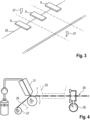
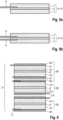
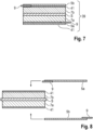
1 bis 8 jeweils unterschiedliche Ansichten, anhand derer Ausführungsbeispiele der erfindungsgemäßen Elektrode veranschaulicht sind.
-
1 to 8 each show different views illustrating embodiments of the electrode according to the invention.
In der
Ein Kern der Erfindung besteht darin, dass die Substratfolie 5 nicht aus einer Metallfolie hergestellt ist, sondern vielmehr aus einem PTFE-Compound mit nicht metallischen, elektrisch leitfähigen Füllstoffen. Solche Füllstoffe sind zum Beispiel Graphitpulver 17 (
Wie aus der
Die Anoden-Substratfolie 5 kann beispielhaft die folgende Zusammensetzung aufweisen:
- -
Graphitpulver 17, insbesondere bis zu 97 Gew% - - PTFE-
Binder 15,insbesondere bis zu 1 Gew% - - gegebenenfalls elektrisch leitfähige
Additive 19, wie etwa Rußpartikel bis zu 2 Gew%, und/oder Kupferpulver.
- -
Graphite powder 17, in particular up to 97 wt% - -
PTFE binder 15, in particular up to 1 wt% - - optionally electrically
conductive additives 19, such as soot particles up to 2% by weight, and/or copper powder.
Alternativ dazu kann die Kathoden-Substratfolie 5 die folgende Zusammensetzung aufweisen:
- -
Graphitpulver 17, insbesondere bis zu 97 Gew%, - - PTFE-
Binder 15,insbesondere bis zu 1 Gew% - - NMC-Partikel oder weiteres Kathodenaktivmaterial, und
- - Aluminiumpulver.
- -
Graphite powder 17, in particular up to 97 wt%, - -
PTFE binder 15, in particular up to 1 wt% - - NMC particles or other cathode active material, and
- - Aluminum powder.
Nachfolgend werden anhand der
In der
Bei einem Verfahren zur Fertigung des Stapelverbunds 39 wird zunächst der Beschichtungsprozess durchgeführt, bei dem die Anodenaktivmaterialschicht 7a und die Kathoden-Aktivmaterialschicht 7b in einem Trockenverfahren auf die beiden Seiten des Separators S beschichtet werden. Anschließend erfolgt ein Klebprozess. In Vorbereitung auf den Klebprozess werden die Außenseiten der Aktivmaterialschichten 7a, 7b mit einem PVDF-Binder 41 überzogen, wie es in der
Gemäß der
BezugszeichenlisteList of reference symbols
- 11
- ZellgehäuseCell housing
- 33
- Elektroden-/Separator-AnordnungElectrode/separator arrangement
- 5, 5a, 5b5, 5a, 5b
- SubstratfolieSubstrate film
- 7, 7a, 7b7, 7a, 7b
- AktivmaterialschichtActive material layer
- 99
- Ableiterfahnearrester lug
- 11, 1311, 13
- ZellableiterCell arrester
- 1515
- PTFE-BinderPTFE binder
- 1717
- GraphitpulverGraphite powder
- 1919
- elektrisch leitfähige Additiveelectrically conductive additives
- 2121
- MischereinheitMixer unit
- 2323
- ExtruderExtruder
- 2525
- Substratfolien-EndlosbahnContinuous substrate film web
- 2727
- Substratfolien-RolleSubstrate film roll
- 2929
- Verbund-EndlosbahnComposite endless track
- 3131
- AuftragswerkzeugApplication tool
- 3333
- TrockenstationDrying station
- 3535
- DickenmessungThickness measurement
- 3737
- SchneidmesserCutting blade
- 3939
- StapelverbundStacked composite
- 4141
- PVDF-BinderPVDF binder
- AA
- Anodeanode
- KK
- Kathodecathode
- SS
- Separatorseparator
ZITATE ENTHALTEN IN DER BESCHREIBUNGQUOTES CONTAINED IN THE DESCRIPTION
Diese Liste der vom Anmelder aufgeführten Dokumente wurde automatisiert erzeugt und ist ausschließlich zur besseren Information des Lesers aufgenommen. Die Liste ist nicht Bestandteil der deutschen Patent- bzw. Gebrauchsmusteranmeldung. Das DPMA übernimmt keinerlei Haftung für etwaige Fehler oder Auslassungen.This list of documents submitted by the applicant was generated automatically and is included solely for the convenience of the reader. This list is not part of the German patent or utility model application. The DPMA assumes no liability for any errors or omissions.
Zitierte PatentliteraturCited patent literature
- WO 2023/122748 A1 [0007]WO 2023/122748 A1 [0007]
Claims (10)
Priority Applications (2)
| Application Number | Priority Date | Filing Date | Title |
|---|---|---|---|
| DE102023211971.4A DE102023211971B4 (en) | 2023-11-29 | 2023-11-29 | Electrode for an electrode-separator arrangement in a battery cell, method for manufacturing such an electrode and battery cell |
| CN202411709536.0A CN120072828A (en) | 2023-11-29 | 2024-11-27 | Electrode for electrode/separator arrangement and method of manufacturing such an electrode |
Applications Claiming Priority (1)
| Application Number | Priority Date | Filing Date | Title |
|---|---|---|---|
| DE102023211971.4A DE102023211971B4 (en) | 2023-11-29 | 2023-11-29 | Electrode for an electrode-separator arrangement in a battery cell, method for manufacturing such an electrode and battery cell |
Publications (2)
| Publication Number | Publication Date |
|---|---|
| DE102023211971A1 true DE102023211971A1 (en) | 2025-06-18 |
| DE102023211971B4 DE102023211971B4 (en) | 2026-01-22 |
Family
ID=95794107
Family Applications (1)
| Application Number | Title | Priority Date | Filing Date |
|---|---|---|---|
| DE102023211971.4A Active DE102023211971B4 (en) | 2023-11-29 | 2023-11-29 | Electrode for an electrode-separator arrangement in a battery cell, method for manufacturing such an electrode and battery cell |
Country Status (2)
| Country | Link |
|---|---|
| CN (1) | CN120072828A (en) |
| DE (1) | DE102023211971B4 (en) |
Citations (1)
| Publication number | Priority date | Publication date | Assignee | Title |
|---|---|---|---|---|
| KR20150086288A (en) * | 2012-11-02 | 2015-07-27 | 넥세온 엘티디 | Device and method of forming a device |
-
2023
- 2023-11-29 DE DE102023211971.4A patent/DE102023211971B4/en active Active
-
2024
- 2024-11-27 CN CN202411709536.0A patent/CN120072828A/en active Pending
Patent Citations (1)
| Publication number | Priority date | Publication date | Assignee | Title |
|---|---|---|---|---|
| KR20150086288A (en) * | 2012-11-02 | 2015-07-27 | 넥세온 엘티디 | Device and method of forming a device |
Also Published As
| Publication number | Publication date |
|---|---|
| CN120072828A (en) | 2025-05-30 |
| DE102023211971B4 (en) | 2026-01-22 |
Similar Documents
| Publication | Publication Date | Title |
|---|---|---|
| DE102018222129A1 (en) | Cathode unit and method for manufacturing a cathode unit | |
| DE102018222142A1 (en) | Method for producing a solid electrolyte membrane or an anode and solid electrolyte membrane or an anode | |
| DE102021124946A1 (en) | SOLID STATE BATTERY AND MANUFACTURING PROCESS | |
| DE3608643A1 (en) | CATHODE FOR LITHIUM DRY BATTERIES AND METHOD FOR THE PRODUCTION THEREOF | |
| DE102016217369A1 (en) | Electrode with increased active material content | |
| DE102018108136A1 (en) | stack battery | |
| DE102012224324B4 (en) | Battery cell, electrode material layer stack and use of an electrode material layer stack in a battery cell | |
| DE102023108210B3 (en) | Process for producing an electrolyte layer supported by a dry-process electrode layer | |
| EP1570113A1 (en) | Method for producing drawn coated metals and use of said metals in the form of a current differentiator for electrochemical components | |
| DE102022101539A1 (en) | ANODE ACTIVE MATERIAL LAYER | |
| DE102023211971B4 (en) | Electrode for an electrode-separator arrangement in a battery cell, method for manufacturing such an electrode and battery cell | |
| DE102021209784A1 (en) | Lithium Ion Battery Cell | |
| DE102023104534B4 (en) | Sandwich-structured, pre-lithiated anode electrode for all-solid-state batteries | |
| DE102017209960A1 (en) | Method for producing an electrode, in particular for a battery | |
| EP4343879A2 (en) | Method for producing a semi-finished product of a solid-state battery, semi-finished product of a solid-state battery and solid-state battery | |
| WO2015197427A1 (en) | Method for producing electrode precursors for a battery | |
| DE102019122226A1 (en) | Composite electrode for a lithium or lithium-ion battery and manufacturing process therefor | |
| EP4449518A1 (en) | Method for producing an electrode having a heterogeneous multiple coating | |
| DE102016217394A1 (en) | Process for the solvent-free production of an electrode | |
| EP4214780A1 (en) | Method for producing a catalyst-coated membrane | |
| DE102023134876B4 (en) | SOLID-BODY BATTERIES | |
| DE102021211680B4 (en) | Electrode for a lithium ion cell, lithium ion cell, method of manufacturing an electrode for a lithium ion cell | |
| DE102013204851A1 (en) | Electrode and method for manufacturing an electrode | |
| DE102020116945B4 (en) | Energy storage device and method for producing an energy storage device | |
| DE102024105841A1 (en) | Method for producing a functional layer arrangement for a solid-state battery |
Legal Events
| Date | Code | Title | Description |
|---|---|---|---|
| R012 | Request for examination validly filed | ||
| R016 | Response to examination communication | ||
| R016 | Response to examination communication | ||
| R018 | Grant decision by examination section/examining division |