DE202008003473U1 - Mobile lifting machine - Google Patents
Mobile lifting machine Download PDFInfo
- Publication number
- DE202008003473U1 DE202008003473U1 DE200820003473 DE202008003473U DE202008003473U1 DE 202008003473 U1 DE202008003473 U1 DE 202008003473U1 DE 200820003473 DE200820003473 DE 200820003473 DE 202008003473 U DE202008003473 U DE 202008003473U DE 202008003473 U1 DE202008003473 U1 DE 202008003473U1
- Authority
- DE
- Germany
- Prior art keywords
- support
- joint
- lifting machine
- wheels
- machine
- Prior art date
- Legal status (The legal status is an assumption and is not a legal conclusion. Google has not performed a legal analysis and makes no representation as to the accuracy of the status listed.)
- Expired - Lifetime
Links
- 238000010276 construction Methods 0.000 description 1
- 238000011090 industrial biotechnology method and process Methods 0.000 description 1
- 238000009434 installation Methods 0.000 description 1
- 238000012423 maintenance Methods 0.000 description 1
- 239000002689 soil Substances 0.000 description 1
Classifications
-
- B—PERFORMING OPERATIONS; TRANSPORTING
- B66—HOISTING; LIFTING; HAULING
- B66C—CRANES; LOAD-ENGAGING ELEMENTS OR DEVICES FOR CRANES, CAPSTANS, WINCHES, OR TACKLES
- B66C23/00—Cranes comprising essentially a beam, boom, or triangular structure acting as a cantilever and mounted for translatory of swinging movements in vertical or horizontal planes or a combination of such movements, e.g. jib-cranes, derricks, tower cranes
- B66C23/62—Constructional features or details
- B66C23/72—Counterweights or supports for balancing lifting couples
- B66C23/78—Supports, e.g. outriggers, for mobile cranes
-
- B—PERFORMING OPERATIONS; TRANSPORTING
- B66—HOISTING; LIFTING; HAULING
- B66F—HOISTING, LIFTING, HAULING OR PUSHING, NOT OTHERWISE PROVIDED FOR, e.g. DEVICES WHICH APPLY A LIFTING OR PUSHING FORCE DIRECTLY TO THE SURFACE OF A LOAD
- B66F11/00—Lifting devices specially adapted for particular uses not otherwise provided for
- B66F11/04—Lifting devices specially adapted for particular uses not otherwise provided for for movable platforms or cabins, e.g. on vehicles, permitting workmen to place themselves in any desired position for carrying out required operations
- B66F11/042—Lifting devices specially adapted for particular uses not otherwise provided for for movable platforms or cabins, e.g. on vehicles, permitting workmen to place themselves in any desired position for carrying out required operations actuated by lazy-tongs mechanisms or articulated levers
Landscapes
- Engineering & Computer Science (AREA)
- Mechanical Engineering (AREA)
- Structural Engineering (AREA)
- Life Sciences & Earth Sciences (AREA)
- Geology (AREA)
- Forklifts And Lifting Vehicles (AREA)
Abstract
Selbstfahrende
Hubarbeitsbühne
1.1
mit einem Fahrgestell (1), umfassend eine Anzahl von Rädern (2);
1.2
mit Stützeinrichtungen
(3), jeweils umfassend eine Stütze
(3.1) sowie einen an deren unteren Ende über ein Gelenk angeschlossenen
Stützteller
(4); gekennzeichnet durch die folgenden Merkmale:
1.3 das Gelenk
ist ein Kardangelenk (5), das zwei zueinander rechtwinklig verlaufende
Gelenkzapfen (5.1, 5.2) aufweist;
1.4 ein erster (5.1) der
beiden Gelenkzapfen befindet sich näher an der Umrisslinie der
Lasthebemaschine, als die Längsmittelachse
der Stütze
(3.1).Self-propelled aerial work platform
1.1 with a chassis (1) comprising a number of wheels (2);
1.2 with support means (3), each comprising a support (3.1) and a support plate (4) connected at its lower end via a hinge; characterized by the following features:
1.3 the joint is a universal joint (5), which has two mutually perpendicular pivot pin (5.1, 5.2);
1.4 a first (5.1) of the two pivot pin is closer to the contour of the lifting machine than the longitudinal center axis of the support (3.1).
Description
Die Erfindung betrifft eine selbstfahrende Hubarbeitsbühne, insbesondere eine selbstfahrende Scherenarbeitsbühne. Eine solche Maschine weist ein Fahrgestell mit einer Anzahl von Rädern auf. Im Allgemeinen handelt es sich um vier Räder. Die Lasthebemaschine umfasst ferner einen Lasthebemechanismus, beispielsweise eine Ausfahrvorrichtung. Die Ausfahrvorrichtung stützt sich mit ihrem unteren Ende auf das Fahrgestell der Maschine, und mit ihrem oberen Ende trägt sie eine Arbeitsbühne. Die Ausfahrvorrichtung kann ein Scherenmechanismus sein, aber auch ein anderer Mechanismus wie beispielsweise eine Teleskopeinrichtung. Im bestimmungsgemäßen Einsatz befinden sich auf der Bühne stets Personen, nämlich Monteure. Die Arbeitsbühne darf gemäß BGR-Vorschriften zum reinen Heben von Lasten nicht verwendet werden. Sie wird speziell eingesetzt für Montage-, Reparatur- und Wartungsarbeiten in allen erreichbaren Höhen. Als Einsatzort kommen Industrieanlagen, aber auch Neubaustellen in Betracht.The The invention relates to a self-propelled aerial work platform, in particular a self-propelled scissor lift. Such a machine has a Chassis with a number of wheels on. Generally it acts it's four wheels. The load lifting machine further comprises a lifting mechanism, for example an extension device. The extension device is supported with its lower end on the chassis of the machine, and with carries her upper end she a working platform. The extension device may be a scissor mechanism, as well another mechanism such as a telescope device. Intended use are always on stage Persons, namely Fitters. The work platform may according to BGR regulations not be used for lifting loads only. She becomes special used for Assembly, repair and maintenance work in all achievable Heights. The place of installation is industrial plants, but also new construction sites into consideration.
Solche fahrbaren Lasthebemaschinen werden überall in der industriellen Technik eingesetzt. Ein wichtiges Einsatzgebiet ist das Beladen und Entladen von Hochregalen. Die Arbeitshöhe kann 20 Meter und mehr erreichen.Such Mobile lifting machines are used throughout the industrial Technique used. One important application is loading and unloading of high shelves. The working height can reach 20 meters and more.
Eine wichtige Eigenschaft solcher fahrbaren Lasthebemaschinen ist deren Standsicherheit. Diese hängt von dem Radabstand ab – gemessen quer zur Fahrtrichtung. Da der Radabstand begrenzt ist, zum Beispiel durch die geringe Breite der Fahrgassen in Hochregallagern, ist auch die Standsicherheit nur begrenzt. Um die Standsicherheit während der Arbeitsphasen der Maschine zu erhöhen, ist eine solche Maschine im Allgemeinen mit Stützeinrichtungen ausgestattet. Die Stützeinrichtungen befinden sich – in Draufsicht auf die Maschine gesehen – im Bereich der Räder, und zwar außerhalb der Räder. Je größer der gegenseitige Abstand zweier Stützeinrichtungen ist, die beidseits der Längsmittelachse der Maschine angeordnet sind, desto größer ist die Standsicherheit. Man ist daher bestrebt, die Stützeinrichtungen so nah wie möglich an die Umrisslinie der Maschine zu legen. Die Ausdrucksweise „Umrisslinie" ist gleich der Außenkontur der Maschine, in Draufsicht gesehen.A important feature of such mobile lifting machines is their Stability. This hangs measured from the wheel distance transverse to the direction of travel. Because the wheelbase is limited, for example due to the small width of the tramlines in high-bay warehouses, is also the stability only limited. To the stability during the To increase work phases of the machine is one such machine generally with support facilities fitted. The support facilities are located - in top view seen on the machine - im Range of wheels, outside the wheels. The bigger the mutual distance between two support devices, the two sides of the longitudinal central axis the machine are arranged, the greater the stability. It is therefore desirable, the support means so as close as possible to put on the outline of the machine. The expression "outline" is equal to the outer contour the machine, seen in plan view.
Vorausgesetzt eine Arbeitsbühne steht auf dem Untergrund absolut eben, bringt das Abstützen innerhalb der Fahrzeugbreite keine beziehungsweise nur eine geringe zusätzliche Standsicherheit. Lediglich die leichte Bewegung in den Gummirädern wird hier ausgeschlossen. Die Stützen haben die Aufgabe, die Maschine unabhängig von den Bodenverhältnissen immer in eine nahezu ebene Arbeitsposition zu bringen. Diese dann gegebene ebene Arbeitsposition ergibt die bestmögliche Standsicherheit. Im Allgemeinen ist eine fahrbare Arbeitsbühne ohne Stützen. Die angebrachten Stützen werden jedoch in letzter Zeit immer häufiger von den Kunden gefordert, um eben den oben genannten Vorteil zu erreichen und der Maschine ein absolut senkrechtes Hochfahren, unabhängig von den gegebenen Bodenneigungen zu gewährleisten. Derselbe Maschinentyp wird auch ohne die Option Stützen gebaut.Provided a work platform is absolutely flat on the ground, bringing support inside the vehicle width no or only a small additional Stability. Only the slight movement in the rubber wheels is here locked out. The pillars have the job of making the machine regardless of the ground conditions always in an almost level working position. This then given level working position gives the best possible stability. in the Generally a mobile working platform without supports. The attached props will be but more and more often lately demanded by the customers to just the above advantage too reach and the machine an absolutely vertical boot, regardless of to ensure the given floor slopes. The same machine type will also support without the option built.
Jede Stützeinrichtung umfasst eine Stütze und einen Stützteller. Der Stützteller ist an das untere Ende der Stütze gelenkig angeschlossen, um Unebenheiten des Bodens wie beispielsweise Schwellen ausgleichen zu können. Die Stütze ist im Allgemeinen eine Stange, die Bestandteil eines Teleskopmechanismus ist.each support means includes a prop and a support plate. The support plate is at the lower end of the prop articulated connected to unevenness of the soil such as To be able to compensate for thresholds. The support is generally a rod that is part of a telescopic mechanism is.
Im Hinblick auf die häufig begrenzten Platzverhältnisse – wiederum vor allem in Hochregallagern – sind der Breite der Maschine Grenzen gesetzt. Die genannte Umrisslinie darf somit auf keinen Fall überschritten werden. Da der Stützteller einer Stütze über deren Längsachse hinausragt, im Aufriss gesehen, kann die Stütze selbst nicht an der Umrisslinie liegen, sondern innerhalb der Umrisslinie.in the Regard to the common limited space - again especially in high-bay warehouses - are the width of the machine limits. The mentioned outline may therefore by no means be exceeded become. Because the backing pad a prop over their longitudinal axis protrudes, viewed in elevation, the support itself can not lie on the outline, but within the outline.
Der Erfindung liegt die Aufgabe zugrunde, eine selbstfahrende Hubarbeitsbühne der genannten Art derart zu gestalten, dass deren Standsicherheit beim Einsatz von Stützeinrichtungen erhöht wird, dass aber die Umrisslinie nicht überschritten wird, und dass keinerlei Teile der Stützeinrichtung, vor allem der Stützteller, nicht über diese Linie hinausragt.Of the Invention is based on the object, a self-propelled aerial work platform mentioned type such that their stability in the Use of support devices elevated but that the outline is not exceeded, and that no parts of the support device, especially the backing pad, no over this line protrudes.
Diese Aufgabe wird durch die Merkmale von Anspruch 1 gelöst.These The object is solved by the features of claim 1.
Die Lösung besteht in Folgendem:
- – das Gelenk ist ein Kardangelenk mit zwei zueinander rechtwinklig verlaufenden Gelenkzapfen
- – ein erster der beiden Gelenkzapfen befindet sich näher an der Umrisslinie der Maschine, als die Längsmittelachse der Stütze.
- - The joint is a universal joint with two mutually perpendicular pivot pin
- - A first of the two pivot pin is closer to the outline of the machine, as the longitudinal center axis of the support.
Der erste der beiden Gelenkzapfen wird sich im Allgemeinen parallel zur Längsmittelachse des Fahrzeuges erstrecken, in Draufsicht gesehen.Of the first of the two pivot pins will generally be parallel to the longitudinal central axis of the vehicle, seen in plan view.
Ist die Stützeinrichtung in Funktion, und liegt der Stützteller demgemäß fest am Boden an, so verläuft der Stützkraftfluss vom Stützteller nach oben zu dem genannten ersten der beiden Gelenkzapfen, wird sodann umgelenkt – im Allgemeinen um 90 Grad – zum zweiten Gelenkzapfen, wird sodann erneut umgelenkt, wiederum im Allgemeinen um 90 Grad, und gelangt zur Stütze, die mehr oder minder senkrecht steht.is the support device in function, and is the backup plate accordingly firmly on Floor on, so runs the supporting force flow from the backing pad up to the said first of the two pivot pins, is then redirected - im Generally around 90 degrees - to second pivot pin is then deflected again, again in Generally around 90 degrees, and gets to the support, which is more or less vertical stands.
Auf diese Weise wird der wirksame Abstand zweier Stützeinrichtungen – quer zur Fahrtrichtung gesehen – vergrößert. Die Vergrößerung mag im Einzelfall nur wenige Zentimeter bewirken. Sie erhöht jedoch die Standfestigkeit außerordentlich.In this way, the effective distance two support devices - viewed transversely to the direction of travel - increased. The magnification may cause only a few centimeters in an individual case. However, it greatly increases the stability.
Gemäß einem weiteren Gedanken der Erfindung könnte statt des Kardangelenkes auch ein Kugelgelenk verwendet werden. Dieses ist wiederum zwischen das untere Ende der Stütze und den Stützteller geschaltet. Jedoch ist die Stütze vor dem Gelenk abgekröpft, und zwar in dem Sinne, dass sich das Kugelgelenk nahe an der Umrisslinie der Lasthebemaschine befindet, und somit außerhalb der Längsmittelachse der Stütze.According to one Another idea of the invention could instead of the universal joint also used a ball joint. This is in turn between the lower end of the support and the backing pad connected. However, the prop is bent in front of the joint, in the sense that the ball joint is close to the outline the lifting machine is located, and thus outside the longitudinal central axis the prop.
In beiden Fällen wird sich der Stützteller im Betriebszustand nach innen erstrecken, das heißt von der Umrisslinie hinweg.In both cases will be the backup plate extend inward in the operating state, that is from the Outline.
Bei der zweiten Ausführungsform mit dem Kugelgelenk wird man dafür sorgen, dass der Stützteller keine Drehbewegung ausführen kann und damit nicht über die Umrisslinie hinausragt.at the second embodiment with the ball joint one becomes one for it make sure the backing pad do not rotate can not and therefore not over the outline protrudes.
Die Erfindung ist anhand der Zeichnung näher erläutert. Darin ist im Einzelnen Folgendes dargestellt:The The invention is explained in more detail with reference to the drawing. This is in detail The following is shown:
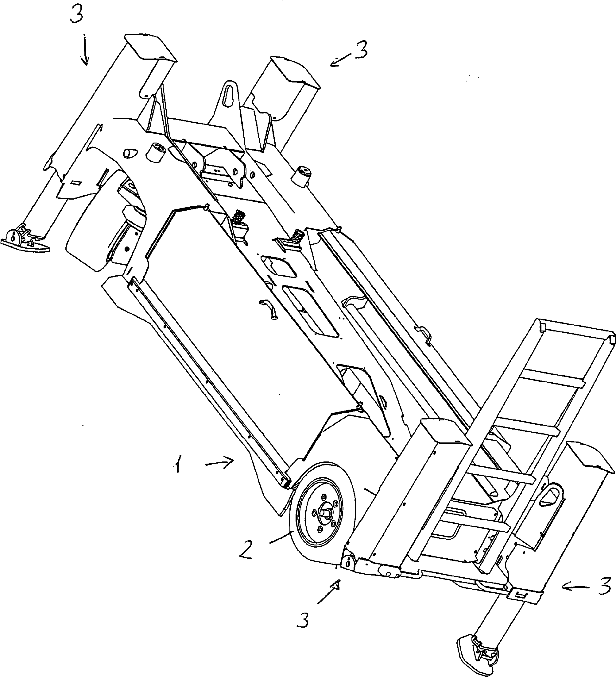
Die
in
Entscheidend
sind vier Stützeinrichtungen
Jede
Stützeinrichtung
umfasst eine Stütze
Man
erkennt ferner einen Stützteller
Das
Kardangelenk
Die
Lagerplatte
Das Wesen der Erfindung lässt sich wie folgt zusammenfassen:
- – der Stützteller ist im Arbeitszustand derart angeordnet, dass er bis zur Umrisslinie reicht, aber nicht darüber hinausragt
- – der Stützkraftfluss findet in jenem Bereich des Stütztellers statt, der sich nahe der Umrisslinie befindet
- – der Stützkraftfluss wird sodann von der Umrisslinie hinweg und zur Längsmittelachse des Fahrzeuges hingeleitet (erste Umlenkung)
- – der Stützkraftfluss wird sodann in die Stützeinrichtung eingeleitet (zweite Umlenkung)
- - The support plate is arranged in the working state such that it extends to the outline, but does not protrude beyond
- - The support force flow takes place in that area of the support plate, which is located near the outline
- - The support force flow is then passed away from the outline and the longitudinal center axis of the vehicle (first deflection)
- The support force flow is then introduced into the support device (second deflection)
- 11
- Fahrgestellchassis
- 22
- Räderbikes
- 33
- Stützeinrichtungsupport means
- 3.13.1
- Stützesupport
- 3.23.2
- Teleskoprohrtelescopic tube
- 44
- Stütztellerbacking pad
- 55
- Kardangelenkuniversal joint
- 5.15.1
- erster Gelenkzapfenfirst pivot pin
- 5.25.2
- zweiter Gelenkzapfensecond pivot pin
- 5.35.3
- Lagerplattebearing plate
Claims (3)
Priority Applications (1)
| Application Number | Priority Date | Filing Date | Title |
|---|---|---|---|
| DE200820003473 DE202008003473U1 (en) | 2008-03-11 | 2008-03-11 | Mobile lifting machine |
Applications Claiming Priority (1)
| Application Number | Priority Date | Filing Date | Title |
|---|---|---|---|
| DE200820003473 DE202008003473U1 (en) | 2008-03-11 | 2008-03-11 | Mobile lifting machine |
Publications (2)
| Publication Number | Publication Date |
|---|---|
| DE202008003473U1 true DE202008003473U1 (en) | 2008-05-29 |
| DE202008003473U8 DE202008003473U8 (en) | 2008-09-25 |
Family
ID=39466240
Family Applications (1)
| Application Number | Title | Priority Date | Filing Date |
|---|---|---|---|
| DE200820003473 Expired - Lifetime DE202008003473U1 (en) | 2008-03-11 | 2008-03-11 | Mobile lifting machine |
Country Status (1)
| Country | Link |
|---|---|
| DE (1) | DE202008003473U1 (en) |
Families Citing this family (1)
| Publication number | Priority date | Publication date | Assignee | Title |
|---|---|---|---|---|
| CN102060244B (en) * | 2010-12-15 | 2012-09-05 | 徐州重型机械有限公司 | Crane and support leg positioning device thereof |
-
2008
- 2008-03-11 DE DE200820003473 patent/DE202008003473U1/en not_active Expired - Lifetime
Also Published As
| Publication number | Publication date |
|---|---|
| DE202008003473U8 (en) | 2008-09-25 |
Similar Documents
| Publication | Publication Date | Title |
|---|---|---|
| EP1900676B1 (en) | Hoisting platform for hoisting loads | |
| DE102014100865B4 (en) | Tugger train trailer with a chassis and a transport device | |
| EP2353976A1 (en) | Track assembly and crawler crane | |
| DE112022002533T5 (en) | Crane and its boom extension method | |
| DE2250428C3 (en) | Lifting device for vehicles, in particular motor vehicles | |
| DE102008013646B3 (en) | Self-propelled aerial work platform | |
| DE202008003473U1 (en) | Mobile lifting machine | |
| EP2969890A1 (en) | Mast assembly for an industrial truck | |
| EP3336048A1 (en) | Shelf serving device | |
| EP2772418B1 (en) | Means to widen a transport device, and transport device | |
| DE102007038047A1 (en) | Tilting device for e.g. laminar concrete prefabricated part, has reinforcing unit, which extends on side turning away from supporting unit, of side guidance unit in opposite direction of supporting unit | |
| EP3197817B1 (en) | Supporting leg and supporting construction for a working machine | |
| AT521719A1 (en) | Device for lifting a vehicle | |
| DE19840151B4 (en) | Support structure for wheeled vehicles | |
| EP2318301B1 (en) | Lift platform | |
| DE1915722A1 (en) | Concrete pump with placing boom | |
| EP0389781A1 (en) | Lifting platform | |
| DE202016001602U1 (en) | hoist | |
| DE202004016639U1 (en) | mobile crane | |
| AT517147B1 (en) | Boom for a commercial vehicle | |
| DE2348164A1 (en) | HIGH WORKING SCAFFOLD | |
| EP0927698B1 (en) | Transversely movable working apparatus on wheels | |
| DE3810070A1 (en) | HEIGHT CONVEYOR CARRIED BY A VEHICLE | |
| DE102008045438A1 (en) | Swing pin for lifting and lowering loads | |
| EP0732300A2 (en) | Mobile working apparatus |
Legal Events
| Date | Code | Title | Description |
|---|---|---|---|
| R207 | Utility model specification |
Effective date: 20080703 |
|
| R156 | Lapse of ip right after 3 years |
Effective date: 20111001 |