EP0000366A1 - Dispositif d'alimentation en feuilles - Google Patents
Dispositif d'alimentation en feuilles Download PDFInfo
- Publication number
- EP0000366A1 EP0000366A1 EP78100292A EP78100292A EP0000366A1 EP 0000366 A1 EP0000366 A1 EP 0000366A1 EP 78100292 A EP78100292 A EP 78100292A EP 78100292 A EP78100292 A EP 78100292A EP 0000366 A1 EP0000366 A1 EP 0000366A1
- Authority
- EP
- European Patent Office
- Prior art keywords
- toothed belt
- suction chamber
- sheet
- cam
- sheet feeder
- Prior art date
- Legal status (The legal status is an assumption and is not a legal conclusion. Google has not performed a legal analysis and makes no representation as to the accuracy of the status listed.)
- Granted
Links
- 230000033001 locomotion Effects 0.000 claims description 11
- 230000002441 reversible effect Effects 0.000 description 2
- 235000004443 Ricinus communis Nutrition 0.000 description 1
- 240000000528 Ricinus communis Species 0.000 description 1
- 230000005540 biological transmission Effects 0.000 description 1
- 230000003139 buffering effect Effects 0.000 description 1
- 238000010276 construction Methods 0.000 description 1
- 230000000694 effects Effects 0.000 description 1
- 239000013013 elastic material Substances 0.000 description 1
- 239000006260 foam Substances 0.000 description 1
- 239000000463 material Substances 0.000 description 1
- 230000000284 resting effect Effects 0.000 description 1
- 238000000926 separation method Methods 0.000 description 1
- 230000001960 triggered effect Effects 0.000 description 1
Images

Classifications
-
- B—PERFORMING OPERATIONS; TRANSPORTING
- B65—CONVEYING; PACKING; STORING; HANDLING THIN OR FILAMENTARY MATERIAL
- B65H—HANDLING THIN OR FILAMENTARY MATERIAL, e.g. SHEETS, WEBS, CABLES
- B65H3/00—Separating articles from piles
- B65H3/08—Separating articles from piles using pneumatic force
- B65H3/12—Suction bands, belts, or tables moving relatively to the pile
- B65H3/122—Suction tables
Definitions
- the invention relates to a sheet feed device for the automatic feeding of single sheets from a stack to a device, with lower transport rollers and upper transport rollers, which bear elastically against the transport rollers.
- DT-OS 2 026 063 thus describes a drum of a copying machine which is provided with a number of protruding gripper fingers which are arranged running over the drum surface and clamp the front edge of the original to be reproduced.
- a gripper device with a clamping strip which has a number of gripper fingers.
- the terminal block is arranged within a drum in a radial slot and is pressed against a clamping surface inside the drum by means of a lever system which actuates an electromagnet with an armature, in order to clamp the template inserted into the slot.
- the gripper device described in DT-OS 2 343 133 is mounted on an endlessly rotating transport system, for example two chains, and consists of a metallic gripper frame which is fastened to the transport chains, movable metallic gripper jaws and buffering cushions, which scratch or otherwise damage the photoconductive drum when the grippers approach prevent device on them.
- German publication 1 902 112 a conveyor device for a copying machine is already known, in which the original to be copied is occasionally fed from a stack to a support surface of an exposure station by means of conveyor belts and then conveyed by conveyor belts is deposited on a storage stack.
- a first switchable conveyor device takes over the separated original and feeds it to the support surface by means of a reversible belt conveyor device which is set in motion by a reversible drive device.
- the known transport devices have in common a master drum, which is equipped with individually integrated gripper fingers or with a rigid gripper bar running over the drum surface, with the help of which the front edge of the original to be transported is held during the rotation of the master drum, or the template is transported by Conveyor belts.
- the known transport devices mentioned are built-in components of a copying or reproducing device and, as such, are not suitable in terms of their construction and function as such for feeding originals from outside an input point of a device in which the originals are further processed.
- the object of the invention is to provide a sheet feeder with which from a stack of single sheets can also have different weights, avoiding double and multiple feed, can be fed to an input point of a device.
- a displaceable in the transport direction of the individual sheets of a stack suction chamber consists of a cover plate and a base plate designed as a perforated plate, and that the cover plate is provided with a suction opening for a fan arranged thereon above the suction opening.
- the suction chamber is laterally delimited by two vertical walls and can be moved between them, and each wall has a slot running in the transport direction, in each of which a guide roller and a stop roller are guided, which extend laterally from the side walls of the suction chamber extend into the slots.
- This configuration ensures that the suction chamber is guided along the slots via the sliding rollers and the stop sliding rollers, the forward movement of the suction chamber being limited by the stop sliding rollers as soon as they abut the ends of the slots.
- the walls are arranged perpendicularly to and connected to a horizontal support plate which receives the stack of sheets and is longer than the walls, viewed in the direction of transport, are deep.
- the platen extends forward beyond the walls, making the stack rests entirely on the platen.
- the height of the stack which can be inserted into the sheet feed device is determined in that the slots and thus the suction chamber with the perforated plate are arranged at a certain distance from the support plate.
- a support rod running parallel to the support plate is connected at its ends to the walls and a spring is attached at one end to the support rod and at the other end to a bolt of the fan housing.
- This spring serves as a return spring for the suction chamber moved in the transport direction.
- An embodiment of the invention is designed so that a drive motor is attached to the inside of one wall, the drive shaft is guided through the wall to the outside and carries two toothed belt pulleys with different diameters, of which the larger toothed belt pulley drives a toothed belt pulley via a toothed belt, which is seated on a common shaft with a gear drive, which sets the shaft arranged at the output of the sheet feed device with the transport rollers in motion, and that the smaller toothed belt pulley drives a toothed belt pulley via a toothed belt, which is firmly connected to a cam on a shaft.
- the cam expediently bears against a cam roller which is seated on the outside of the wall on the same axis as the slide roller and, during one revolution, shifts the suction chamber by one cam length against the tensile force of the spring in the transport direction against the tensile force of the spring.
- a drive motor is attached to the inside of one wall, the drive shaft of which is guided through the wall and on which a toothed belt pulley is seated, which drives a belt drive, which acts as an endless toothed belt via a toothed belt pulley seated on the shaft with the transport rollers and is guided over a toothed belt pulley which is firmly connected to the cam.
- This drive mechanism represents a structural simplification compared to the drive mechanism described above.
- the advantages are achieved that the suction of a single sheet while simultaneously feeding the same ensures a safe and trouble-free individual feed to a device, such as a facsimile machine, and that the ease of use of such a device is increased by the automatic loading.
- a device such as a facsimile machine
- Another advantage is that the sheet feeder to a facsimile machine can be reduced in cost by reducing the cost of transmission by the facsimile machine for a period of time used lines can be sent automatically without the need for personnel if the sheet feeder is triggered automatically, for example by a timer.
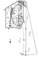
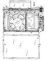
- FIGS. 1 and 2 show a side and a front view of a sheet feed device 1 which has a suction chamber 3 which can be displaced in the transport direction A.
- a fan 4, which is not shown in FIG Way is connected to the electrical power supply.
- a suction opening 21 for the fan 4 shown in FIG. 3 is provided in the cover plate 22.
- the base plate of the suction chamber 3 is designed as a perforated plate 2, so that during operation of the fan 4 through the perforated plate 2, a constant air draft is directed upwards, which lifts the sheet 13 lying on top from a stack 16.
- the suction chamber 3 has the shape of a flat box, which can be moved with its side walls between vertical walls 23, 24.
- the walls 23, 24 form a right angle with a support plate 27 which receives the stack 16 of sheets 13 and are connected to it.
- the length and the width of the support plate 27 are chosen according to the largest sheet format still to be processed.
- the front or rear edge of the support plate 27 delimits a stop 11 or 11 '.
- the stop 11 ' is usually arranged at a short distance in front of the rear edge of the support plate 27 and is tangent to the transport rollers 10.
- the transport rollers 10 usually consist of an elastic material, such as rubber or the like, while the material for the transport rollers 9 is preferably an elastic foam.
- the support plate 27 is longer than the walls 23, 24, seen in the transport direction A, is deep and extends beyond the walls 23, 24 to the front.
- a cover 39 which can be provided with holes, for example, covers the sheet feed device 1 from above and furthermore, as a cover 37, also encloses a drive arrangement for the transport rollers 9 and a cam 5 which moves the suction chamber 3 in the transport direction A.
- a start and a stop button are provided, between which a display, for example in the form of a lamp, is arranged which indicates the start of operation of the sheet feeder after the start button has been pressed and the end of the sheet feeder.
- the perforated plate 2 of the suction chamber 3 is arranged at a certain distance from the support plate 27, which defines the height of the stack 16 that can be inserted into the sheet feeder 1.
- a support rod 19 which runs parallel to the support plate 27 and is connected at its ends to the walls 23, 24. This can be done, for example, in such a way that the ends of the holding rod 19, which have threads, are passed through holes in the walls 23, 24 and on the outer sides the walls 23, 24 are screwed together using nuts.
- One end of a spring 7 is hooked onto the mounting rod 19, while the other end of the spring 7 is hooked onto a bolt 15 of the fan housing 14.
- the spring 7, which runs slightly obliquely to the horizontal, works as a return spring for the suction chamber 3 and pulls it back into the starting position after the forward movement has taken place.
- a drive motor 8 is provided on the inside of the wall 23, the drive shaft 29 (FIG. 2) of which is guided through the wall 23.
- a toothed belt pulley 30 which drives a belt drive 17 which, as an endless toothed belt, is guided via a toothed belt pulley 36 seated on the shaft 38 with the transport rollers 9 and via a further toothed belt pulley 18 which is firmly connected to the cam 5 .
- This drive arrangement can be seen in FIG. 1, in which the cover 37 shown in FIG. 2 has been removed.
- the cam 5 which bears against a cam roller 6, is rotated and during. one revolution, the suction chamber 3 is shifted via the cam roller 6 against the tensile force of the spring 7 in the transport direction A by one cam length from the starting position.
- the cam 5 bears against the cam roller 6, which slides forward in the slot 25 as long as the cam diameter becomes larger.
- the diameter of the cam 5 resting against the cam roller 6 becomes smaller again, so that the spring 7 can pull the suction chamber 3 back into the starting position.
- the drive arrangement sets the transport rollers 9 in rotation, which abut against the transport rollers 10 and together with them detect the leading edge of a fed sheet and, for example, convey it to the entry point of a remote copier, not shown.
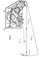
- guide projections 20 are provided for the sheet 13 to be transported across the width of the chamber, as the top view according to FIG. 3 shows. These guide projections 20 lie in the advanced position of the suction chamber 3 tangentially on the lower edge of the shaft 38 and ensure an exact grasping and drawing in of the transported sheet by the transport rollers 9 and the transport rollers 10.
- two transport rollers are shown, but can more than two transport rollers or a single continuous transport roller can also be provided.
- the guide projections 20 lie opposite the section of the shaft 38 between two adjacent transport rollers 9 or the section between the wall 23 or 24 and the adjacent transport roller 9. This ensures that during the forward movement of the suction chamber 3, the guide projections 20 each have space between two transport rollers 9 or a transport roller 9 and the wall 23 or 24.
- the suction chamber 3 is guided between the walls 23, 24 in the exemplary embodiment shown in FIGS. 1 to 3 in such a way that a groove 41 extending over the entire length of the wall is provided on the inside of each wall 23, 24 is, with each groove two castors 42 (see Fig. 2 and 3) are engaged.
- the slide rollers 42 are mounted horizontally between the walls 23, 24 and recesses in the side walls of the suction chamber 3 and ensure an almost smooth movement of the suction chamber 3.
- each wall 23, 24 has a slot 25, which runs parallel to the support plate 27 and is shorter than the adjacent side wall of the suction chamber 3.
- Two shafts protrude from the side walls of the suction chamber 3, on which a slide roller 26 and a stop slide roller 28 are seated, which engage in the slots 25 of the walls 23, 24.
- the stop slide roller 28 limits the forward movement of the suction chamber 3 as soon as it bears against the rear end of the slot 25.
- a cam roller 5 is seated on the shaft 35 on the outside of the wall 23.
- a drive motor 8 is also attached to the inside of the wall 23, the drive shaft 29 of which is guided through the wall 23 to the outside.
- the gear drive 34 consists of two gear wheels, which are connected to one another by a self-contained endless gear chain. The gear drive sets the shaft arranged at the output of the sheet feed device 1 in motion with the transport rollers 9.
- the smaller toothed belt pulley 31 on the drive shaft 29 drives a toothed belt pulley 40 via a toothed belt 33, which is fixedly connected to the cam 5 on the shaft 35. Due to the rotation of the cam 5, the suction chamber 3 is moved in the manner already described above.
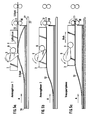
- a first sheet 13 from the stack 16 is gripped by the transport rollers 9 and the transport rollers 10 and conveyed to the feed rollers of a downstream device, not shown.
- the first sheet still partially covers the perforated plate of the suction chamber 3.
- a second sheet of the stack 16 is sucked in by the uncovered part of the perforated plate of the suction chamber and shows a curved course.
- the suction chamber 3 is still in its initial position.
- the suction force of the fan 4 on the second sheet is approximately 70% of the full suction force and increases continuously as the first sheet progresses into the downstream device.
- the second sheet is more or less curved. Due to the continuously increasing suction power of the fan on the second sheet and the weight of an approximately subsequent third sheet, a separation effect is achieved between these two sheets, which prevents double or multiple feeding of sheets with certainty.
- the sheet 13 completely covers the perforated plate of the suction chamber 3 and the cam 5 begins to rotate and to shift the slide roller in the transport direction A, as a result of which the suction chamber 3 is moved.
- the perforated plate ensures a largely wide-area suction with approximately laminar flow, whereby the covering of the edge zones prevents unwanted air vortices that can lead to double or multiple feeding of sheets.
Landscapes
- Engineering & Computer Science (AREA)
- Mechanical Engineering (AREA)
- Sheets, Magazines, And Separation Thereof (AREA)
Applications Claiming Priority (2)
| Application Number | Priority Date | Filing Date | Title |
|---|---|---|---|
| DE2731095 | 1977-07-09 | ||
| DE19772731095 DE2731095A1 (de) | 1977-07-09 | 1977-07-09 | Blattzufuhrvorrichtung |
Publications (2)
| Publication Number | Publication Date |
|---|---|
| EP0000366A1 true EP0000366A1 (fr) | 1979-01-24 |
| EP0000366B1 EP0000366B1 (fr) | 1980-04-30 |
Family
ID=6013542
Family Applications (1)
| Application Number | Title | Priority Date | Filing Date |
|---|---|---|---|
| EP78100292A Expired EP0000366B1 (fr) | 1977-07-09 | 1978-07-03 | Dispositif d'alimentation en feuilles |
Country Status (7)
| Country | Link |
|---|---|
| US (1) | US4280691A (fr) |
| EP (1) | EP0000366B1 (fr) |
| JP (1) | JPS5418579A (fr) |
| AT (1) | AT357030B (fr) |
| CA (1) | CA1086342A (fr) |
| DE (2) | DE2731095A1 (fr) |
| IT (1) | IT1105754B (fr) |
Families Citing this family (5)
| Publication number | Priority date | Publication date | Assignee | Title |
|---|---|---|---|---|
| EP0514618B2 (fr) * | 1991-05-08 | 2000-05-10 | Mars, Incorporated | Stock provisoire |
| HUT61622A (en) * | 1991-05-08 | 1993-01-28 | Landis & Gyr Betriebs Ag | Intermediate card-container |
| US5803447A (en) * | 1996-09-25 | 1998-09-08 | D&K Custom Machine Design, Inc. | Method and apparatus for feeding sheets |
| US7002714B1 (en) * | 2000-11-17 | 2006-02-21 | Stephen Neushul | Autofeeder for X-ray scanning |
| US7559549B2 (en) * | 2006-12-21 | 2009-07-14 | Xerox Corporation | Media feeder feed rate |
Citations (4)
| Publication number | Priority date | Publication date | Assignee | Title |
|---|---|---|---|---|
| US1435205A (en) * | 1920-02-16 | 1922-11-14 | Harry L Brigham | Pneumatic sheet feeder |
| US2859964A (en) * | 1957-02-19 | 1958-11-11 | Theodore F Aronson | Sheet feeding mechanism |
| US3226108A (en) * | 1961-11-11 | 1965-12-28 | Deritend Eng Co | Suction feed mechanism for corrugated and like cardboard |
| US3610577A (en) * | 1969-02-06 | 1971-10-05 | Joseph E Foster Jr | Suction feed conveyor |
Family Cites Families (11)
| Publication number | Priority date | Publication date | Assignee | Title |
|---|---|---|---|---|
| GB212097A (en) | 1923-02-27 | 1924-03-06 | Robert Charles Adams | An improved suction feed device for rotary duplicators, printing apparatus, and the like |
| NL294543A (fr) * | 1962-07-09 | |||
| US3265383A (en) * | 1965-04-22 | 1966-08-09 | Eastman Kodak Co | Film sheet feeder |
| US3501138A (en) * | 1967-08-30 | 1970-03-17 | Fmc Corp | Sheet dispenser |
| GB1289282A (fr) | 1969-02-26 | 1972-09-13 | ||
| US3614089A (en) * | 1969-06-16 | 1971-10-19 | Copystatics Mfg Corp | Automatic original feeder for copying machine |
| US3595563A (en) | 1969-09-15 | 1971-07-27 | Olivetti & Co Spa | Sheet-feeding apparatus |
| US3659838A (en) * | 1970-06-12 | 1972-05-02 | J W Hassell Jr | Material handling device |
| US3674367A (en) * | 1970-06-15 | 1972-07-04 | Time Inc | Method for handling and positioning film |
| DD112841A1 (fr) | 1974-04-10 | 1975-05-05 | ||
| FR2362065A1 (fr) | 1976-08-20 | 1978-03-17 | Ricoh Kk | Distributeur de feuilles, notamment pour la reprographie |
-
1977
- 1977-07-09 DE DE19772731095 patent/DE2731095A1/de not_active Withdrawn
-
1978
- 1978-07-03 EP EP78100292A patent/EP0000366B1/fr not_active Expired
- 1978-07-03 DE DE7878100292T patent/DE2857618D1/de not_active Expired
- 1978-07-05 JP JP8186578A patent/JPS5418579A/ja active Pending
- 1978-07-06 CA CA306,900A patent/CA1086342A/fr not_active Expired
- 1978-07-07 AT AT493978A patent/AT357030B/de not_active IP Right Cessation
- 1978-07-07 US US05/922,746 patent/US4280691A/en not_active Expired - Lifetime
- 1978-07-07 IT IT50201/78A patent/IT1105754B/it active
Patent Citations (4)
| Publication number | Priority date | Publication date | Assignee | Title |
|---|---|---|---|---|
| US1435205A (en) * | 1920-02-16 | 1922-11-14 | Harry L Brigham | Pneumatic sheet feeder |
| US2859964A (en) * | 1957-02-19 | 1958-11-11 | Theodore F Aronson | Sheet feeding mechanism |
| US3226108A (en) * | 1961-11-11 | 1965-12-28 | Deritend Eng Co | Suction feed mechanism for corrugated and like cardboard |
| US3610577A (en) * | 1969-02-06 | 1971-10-05 | Joseph E Foster Jr | Suction feed conveyor |
Also Published As
| Publication number | Publication date |
|---|---|
| DE2731095A1 (de) | 1979-01-11 |
| AT357030B (de) | 1980-06-10 |
| EP0000366B1 (fr) | 1980-04-30 |
| CA1086342A (fr) | 1980-09-23 |
| US4280691A (en) | 1981-07-28 |
| IT1105754B (it) | 1985-11-04 |
| JPS5418579A (en) | 1979-02-10 |
| IT7850201A0 (it) | 1978-07-07 |
| DE2857618D1 (en) | 1980-06-12 |
Similar Documents
| Publication | Publication Date | Title |
|---|---|---|
| DE2805674C2 (de) | Vorrichtung zur Zuführung von blattförmigen Vorlagen zu einer Belichtungsstation eines Kopiergerätes | |
| DE3347773C2 (fr) | ||
| DE2854695C2 (de) | Transportvorrichtung für blattförmige Aufzeichnungsträger | |
| EP0550828B1 (fr) | Procédé et dispositif de traitement de produits imprimés | |
| DE3306305C2 (fr) | ||
| DE2647265C2 (de) | Zuführvorrichtung für ein Fotokopiergerät | |
| DE2908398A1 (de) | Dokumenten-zufuehrvorrichtung fuer kopiergeraete | |
| DE3022285C2 (de) | Vorrichtung zum Stapeln von Blättern, wie Papier - Geldscheinen | |
| DE2711173B2 (de) | Einrichtung an einer schreibenden oder druckenden Büromaschine zum Beschicken derselben mit Blättern | |
| DE3537495A1 (de) | Papierzufuehrungsvorrichtung | |
| EP0529490A1 (fr) | Margeur de feuilles | |
| DE4225607A1 (de) | Umsteuerbare kollationiermaschine | |
| DE3108044C2 (de) | Vorrichtung zur Handhabung von Materialbogen | |
| DE4013428C2 (de) | Automatische vorlagenzufuehreinrichtung fuer ein kopiergeraet | |
| DE3023533A1 (de) | Vorrichtung zum ablegen von bogen in einem stapel | |
| DE3817587A1 (de) | Blattfoerdervorrichtung | |
| DE2023280A1 (de) | Automatische Zuführeinrichtung zum aufeinanderfolgenden Zuführen von einzelnen Blättern von einem Stapel | |
| EP0000366B1 (fr) | Dispositif d'alimentation en feuilles | |
| EP0128352B1 (fr) | Dispositif de transport et d'empilage de feuilles | |
| DE3873906T2 (de) | Drahtfuehrung bei einer drahterosionsbearbeitungsvorrichtung. | |
| DE68910315T2 (de) | Transport- und sortiersystem für ein flexibles werkstück. | |
| DE2546438C3 (de) | Transportvorrichtung in einem Kopiergerät zum repetierenden Transport einer Kopiervorlage | |
| DE2257303A1 (de) | Dokumentenfoerdergeraet zur ueberfuehrung von in einem stapel gespeicherten dokumenten, insbesondere fuer die einem kopiergeraet zuzufuehrenden originale | |
| DE1422980A1 (de) | Kopiergeraet | |
| DE69918581T2 (de) | Verbesserte Bandzuführvorrichtung |
Legal Events
| Date | Code | Title | Description |
|---|---|---|---|
| PUAI | Public reference made under article 153(3) epc to a published international application that has entered the european phase |
Free format text: ORIGINAL CODE: 0009012 |
|
| AK | Designated contracting states |
Designated state(s): BE DE FR GB NL |
|
| 17P | Request for examination filed | ||
| GRAA | (expected) grant |
Free format text: ORIGINAL CODE: 0009210 |
|
| AK | Designated contracting states |
Designated state(s): BE DE FR GB NL |
|
| REF | Corresponds to: |
Ref document number: 2857618 Country of ref document: DE Date of ref document: 19800612 |
|
| PLBI | Opposition filed |
Free format text: ORIGINAL CODE: 0009260 |
|
| 26 | Opposition filed |
Opponent name: OCE-NEDERLAND B.V. Effective date: 19810129 |
|
| PGFP | Annual fee paid to national office [announced via postgrant information from national office to epo] |
Ref country code: NL Payment date: 19830615 Year of fee payment: 6 |
|
| PGFP | Annual fee paid to national office [announced via postgrant information from national office to epo] |
Ref country code: FR Payment date: 19830616 Year of fee payment: 6 |
|
| PGFP | Annual fee paid to national office [announced via postgrant information from national office to epo] |
Ref country code: BE Payment date: 19830630 Year of fee payment: 6 |
|
| PGFP | Annual fee paid to national office [announced via postgrant information from national office to epo] |
Ref country code: DE Payment date: 19830815 Year of fee payment: 6 |
|
| RDAG | Patent revoked |
Free format text: ORIGINAL CODE: 0009271 |
|
| STAA | Information on the status of an ep patent application or granted ep patent |
Free format text: STATUS: PATENT REVOKED |
|
| 27W | Patent revoked |
Effective date: 19830915 |
|
| BERE | Be: lapsed |
Owner name: HOECHST A.G. Effective date: 19840703 |
|
| GBPC | Gb: european patent ceased through non-payment of renewal fee | ||
| REG | Reference to a national code |
Ref country code: FR Ref legal event code: ST |