EP0000413A1 - Mécanisme d'entrainement pour imprimantes, applicable soit pour le transport ou l'inversion d'un ruban encreur soit pour le basculement de la tête d'impression - Google Patents
Mécanisme d'entrainement pour imprimantes, applicable soit pour le transport ou l'inversion d'un ruban encreur soit pour le basculement de la tête d'impression Download PDFInfo
- Publication number
- EP0000413A1 EP0000413A1 EP78200075A EP78200075A EP0000413A1 EP 0000413 A1 EP0000413 A1 EP 0000413A1 EP 78200075 A EP78200075 A EP 78200075A EP 78200075 A EP78200075 A EP 78200075A EP 0000413 A1 EP0000413 A1 EP 0000413A1
- Authority
- EP
- European Patent Office
- Prior art keywords
- lever
- ribbon
- print head
- ink ribbon
- shift
- Prior art date
- Legal status (The legal status is an assumption and is not a legal conclusion. Google has not performed a legal analysis and makes no representation as to the accuracy of the status listed.)
- Granted
Links
- 230000002250 progressing effect Effects 0.000 title 1
- 238000005096 rolling process Methods 0.000 claims abstract description 12
- 230000002441 reversible effect Effects 0.000 claims abstract description 3
- 238000013459 approach Methods 0.000 claims description 6
- 239000000969 carrier Substances 0.000 claims description 6
- 238000006073 displacement reaction Methods 0.000 description 6
- 230000000694 effects Effects 0.000 description 2
- 230000005540 biological transmission Effects 0.000 description 1
- 238000006243 chemical reaction Methods 0.000 description 1
- 238000004519 manufacturing process Methods 0.000 description 1
- 239000002184 metal Substances 0.000 description 1
- 238000000034 method Methods 0.000 description 1
- 230000000452 restraining effect Effects 0.000 description 1
- 125000006850 spacer group Chemical group 0.000 description 1
Images


Classifications
-
- B—PERFORMING OPERATIONS; TRANSPORTING
- B41—PRINTING; LINING MACHINES; TYPEWRITERS; STAMPS
- B41J—TYPEWRITERS; SELECTIVE PRINTING MECHANISMS, i.e. MECHANISMS PRINTING OTHERWISE THAN FROM A FORME; CORRECTION OF TYPOGRAPHICAL ERRORS
- B41J23/00—Power drives for actions or mechanisms
- B41J23/02—Mechanical power drives
- B41J23/025—Mechanical power drives using a single or common power source for two or more functions
-
- B—PERFORMING OPERATIONS; TRANSPORTING
- B41—PRINTING; LINING MACHINES; TYPEWRITERS; STAMPS
- B41J—TYPEWRITERS; SELECTIVE PRINTING MECHANISMS, i.e. MECHANISMS PRINTING OTHERWISE THAN FROM A FORME; CORRECTION OF TYPOGRAPHICAL ERRORS
- B41J33/00—Apparatus or arrangements for feeding ink ribbons or like character-size impression-transfer material
- B41J33/14—Ribbon-feed devices or mechanisms
- B41J33/40—Ribbon-feed devices or mechanisms with arrangements for reversing the feed direction
- B41J33/44—Ribbon-feed devices or mechanisms with arrangements for reversing the feed direction automatically
- B41J33/51—Ribbon-feed devices or mechanisms with arrangements for reversing the feed direction automatically and characterised by the use of particular reversing control means
- B41J33/518—Ribbon-feed devices or mechanisms with arrangements for reversing the feed direction automatically and characterised by the use of particular reversing control means the reversing-feeler engaging buttons or the like secured to the ribbon near its ends
Definitions
- the invention relates to a drive device for the necessary transport or switching of an ink ribbon and for pivoting the print head from the print abutment in printing devices of a typewriter or booking machine, in which the switching and transportation of the ink ribbon takes place by means of gearwheels which are firmly connected to one another by a shift shaft and by longitudinal displacement the switching shaft alternately come into engagement in the associated sprockets of the bobbin arranged on the side of the printing device, and in which the swiveling of the print head takes place by tightening a pulling rope which is fastened on one side of the printing device and is guided past the print head via deflection rollers.
- each spool is assigned a gear, in particular worm gear. These two gears are connected to each other via a selector shaft, which is slidably mounted. Once the ribbon has been unwound, further movement of the ribbon through the empty spool is stopped.
- the shift shaft actuated by a motor via a gear transmission is moved further in the previous direction, so that a force is exerted in the longitudinal direction of the shift shaft via the driving worm wheel. That power causes a displacement of the shaft as soon as it is greater than the force of a dead center switching device which prevents this displacement.
- the electric motor required for this drive device always rotates in the same direction.
- a pivoting device in which a pull rope is used, which is attached on one side of the printing device, while it is connected on the other side to a pivot lever.
- the traction cable is deflected by at least three rollers, two of which are on the side of the printhead on the carriage and one in the direction of the platen on the printhead are stored. If the swivel lever is actuated, the rope is tightened and thereby the roller on the print head is pulled in the direction of the plane formed by the two rollers of the carriage.
- an electric motor is provided which is switched as required.
- the invention has for its object to provide a device that can be used both for driving a transport and switching device for the ribbon as well as for pulling the printing unit, so that only one electric motor is provided for both types of drive and in which the Conversion required ribbon tension forces are as low as possible and the structure is simple. It is assumed that both types of drive do not take effect at the same time, because a typewriter is used in typewriters and booking machines never do this with the printhead down.
- the electrical control of the electric motor is technically simpler and can easily be derived from the half-speed clutch via switching devices. Since the half-speed clutch is freely supported on the common drive axle during transport and a changeover of the ink ribbon, it is advisable to provide the half-speed clutch with a second cam disc with two approximately diametrically opposite recesses, in which a fixing lever for locking the two end positions of the pivoting lever can be locked .
- the interconnected gears and the associated gear rings of the coil carriers are expediently provided with conical projections, the conical surfaces of which are directed towards one another and rub against one another in the opposite direction of rotation, as long as the gear wheels and the associated gear rings are disengaged. If the two assigned gears are disengaged after switching the transport direction of the ribbon, the sprockets of the gears connected to one another are freely movable in grooves, each between the sprocket and the conical shoulder of the coil carrier are arranged. Since these non-intermeshing sprockets are driven in opposite directions on the one hand by the drive device and on the other hand by the ink ribbon, both conical projections grind against one another. As a result, the drawn bobbin is braked and the unwinding ribbon is kept taut.
- a gear lever is assigned to each gear on the shift shaft, which is pivoted by the ribbon against the end face of the assigned gear, that at least one of these shift levers is assigned a roller lever that can be moved against a spring force, and that the rolling plane is in the area of action of this roller lever of the shift lever has a roof-shaped cross section.
- Both shift levers are suitably rigidly connected to one another.
- the length of the run-up slope of the roof-shaped rolling plane is somewhat smaller than the distances between the shift levers and the associated gear wheels.
- the shift levers are provided with lugs.
- the printing device shown in the drawings consists of the housing walls 36 and 361, which are connected to one another by the spacer rails 27 and 28.
- the pressure abutment 53 and the slide rails for the transport carriage 56 of the print head 49 are fastened in the side walls 36 and 361.
- the hollow shaft 10 is also fixed, in which the control shaft 8 is rotatably and slidably mounted.
- Gears 7 and 9 are fixedly arranged on the ends of the selector shaft 8 projecting beyond the housing walls. These gear wheels 7 and 9 alternately engage with gear rings 141 and 131 assigned to them by shifting the selector shaft 8.
- These sprockets are part of assigned spool supports 13 and 14, on the mandrels 16 and 29 of which the ribbon spools 11 and 12 are attached.
- the ribbon spools 11 and 12, which mostly consist of sheet metal, are held by permanent magnets 15 (shown only on one side).
- the ink ribbon 17 is guided over the rear deflection rollers 55 and 551 and over the front deflection rollers 54 and 541 on the front side of the print head 49. All pulleys are stored on the removable print head.
- Both gear wheels 7 and 9 and both coil carriers 13 and 14 have conical projections 71, 91 or 132 and 142, the conical surfaces of which are directed towards one another.
- the conical surfaces 71 and 142 of the gear 7 and the associated Ring gear 141 come into contact when the gear and ring gear are disengaged after the switching operation.
- the gear 9 and ring gear 131 are in engagement with one another, and the conical surfaces 91 and 132 are not in contact with one another.
- the gear 7 and the ring gear 141 are disengaged, while the conical surfaces 71 and 142 touch. If the control shaft 8 is driven via the gear 7, the spool 13 and thus the ribbon reel 11 are driven via the gear 9.
- the ribbon 17 is thereby rewound from the ribbon spool 12 to the ribbon spool 11.
- the gear 7 and the coil carrier 14 make opposite rotational movements, so that the surfaces of the cones 71 and 142 rub against each other.
- This frictional force exerts a force on the ribbon spool 12 against the unwinding direction, which causes the ribbon 17 to be tightened continuously.
- this tightening is achieved by the frictional forces between the bevel gears 91 and 132.
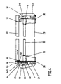
- the shift of the control shaft 8 and thus the switching of the transport direction of the ink ribbon 17 is described in more detail below with reference to FIG. 4.
- an angle bracket 35 is attached, on which a gear consisting of the gears 3, 4 and 5 is mounted.
- This gear is driven by the gear 2 of an electric motor 1, which is attached to the housing wall 36.
- the gear wheel 5 is fastened on a drive shaft 37 which is mounted in the housing wall 36 and the angle bracket 35.
- This axis 37 is the common drive axis for the ribbon transport and the pivoting of the print head.
- a gear 6 is arranged on the axis 37, which is driven by a directional lock 65 from the shaft 37 and which is constantly in operative connection with the gear 7.
- the locking direction of the directional lock 65 is selected so that when the common axis 37 is driven by the electric motor 1 in one direction the driving force is transmitted to the gear 7, but not when the axis 37 is rotating in the opposite direction.
- the drive shaft 37 which is rotatably arranged in the housing wall 36 in the bearing 39, is extended beyond the bearing point 38 in the angle bracket 35 and bears the curved part of a half-speed clutch on this extension.
- This curve piece is mounted on a directional lock 44 on this common drive shaft 37, the locking direction of which is opposite to the locking direction of the locking mechanism 65. This means that when the directional lock 65 is locked, the directional lock 44 is not locked. If, however, the directional lock 65 is free-running, the directional lock 44 locks and thus transmits the driving force emanating from the electric motor 1 to the half-speed clutch.
- the half-speed clutch has two cams 40 and 59. With both cams, two levers 43 and 58 are controlled, which are mounted on a common axis of rotation 57.
- the lever 43 is connected at one end to the housing wall 36 via a spring 66 and, as a result of this spring force, engages with its support roller 61 in recesses in the cam plate 59. These recesses are approximately diametrically opposite and cause the half-speed clutch to be locked in the two end positions of the pivoting lever 58, which is pivoted back and forth with the support roller on the cam disk 40 about the pivot point 57.
- This pivoting lever 58 has a shoulder 52 to which the pull cable 46 is fastened at one end.
- the cable is deflected to the print head 49 via a deflection roller 51 and fastened to a leaf spring 45 on the other side of the printing device, which in turn is firmly connected to the housing wall 361. With the aid of the adjusting screw 63, length tolerances of the rope 46 can be compensated for.
- the rope 46 is steered via three deflection rollers 47, 48 and 50.
- the rollers 47 and 48 are mounted on the carriage 56, while the roller 50 be on the front part of the print head 49 is consolidated.
- the electric motor 1 is excited again and the half-speed clutch is rotated a further half turn via the directional lock 44.
- the microswitch 42 is actuated, which now initiates a reversal of the electric motor.
- the pivot lever 58 will again assume its position shown in FIG. 3 and loosen the cable 46. Due to a spring force, not shown, the print head 49 is moved in the direction of the platen 53.
- the directional lock 65 is now effective by reversing the direction of the drive axis 37 and thus also the ribbon transport or, if necessary, the ribbon switchover.
- the ribbon 17 has, as shown in Fig. 4, at both ends of the eyelets 18 through which the respective associated shift levers 19 and 20 are pivoted.
- the shift levers 19 and 20 are pivotally mounted in bearings 21 and 22 on the housing walls 36 and 361. At one end they are rigidly coupled to one another by a connecting rod 23. I.e. they always make the same movements. At their other ends, the shift levers 19 and 20 are provided with fork-shaped projections 30 and 31 through which the ribbon 17 slides.
- a roller lever is additionally arranged displaceably on the housing wall 36.
- the displacement of the roller lever is directed perpendicular to the control shaft 8 within the plane of the drawing.
- the roller lever 24 In its drawn rest position, the roller lever 24 is held by the force of a tension spring 25.
- the side edge of the lever 19 is roof-shaped.
- the rolling plane 34 for the roller lever 24 thus consists of a run-up slope 341 and a run-off slope 342.
- the shift lever 20 is also formed with these slopes in the present exemplary embodiment. This is only for manufacturing reasons, since in this way both shift levers 19 and 20 are the same stamped parts.
- the shift levers 19 and 20 have lugs 26 and 33, which rest in the operative position of the shift levers 19 and 20 on the gears 7 and 9 and are lifted from the latter in the rest position.
- the position of the shift lever 20 shown on the right in FIG. 4 thus represents the active position, while the position of the shift lever 19 shown on the left in FIG. 4 is the rest position.
Landscapes
- Impression-Transfer Materials And Handling Thereof (AREA)
- Character Spaces And Line Spaces In Printers (AREA)
Applications Claiming Priority (4)
| Application Number | Priority Date | Filing Date | Title |
|---|---|---|---|
| DE2731593 | 1977-07-13 | ||
| DE19772731593 DE2731593C3 (de) | 1977-07-13 | 1977-07-13 | Vorrichtung zum Umkehren der Bewegungsrichtung eines Farbbandes in Schreib- und Buchungsmaschinen |
| DE2731607 | 1977-07-13 | ||
| DE19772731607 DE2731607C3 (de) | 1977-07-13 | 1977-07-13 | Antriebsvorrichtung zum bedarfsweisen Transport bzw. Umkehren der Transportrichtung eines Farbbandes und zum Abschwenken des Druckkopfes in Druckeinrichtungen |
Publications (2)
| Publication Number | Publication Date |
|---|---|
| EP0000413A1 true EP0000413A1 (fr) | 1979-01-24 |
| EP0000413B1 EP0000413B1 (fr) | 1980-12-10 |
Family
ID=25772317
Family Applications (1)
| Application Number | Title | Priority Date | Filing Date |
|---|---|---|---|
| EP78200075A Expired EP0000413B1 (fr) | 1977-07-13 | 1978-07-03 | Mécanisme d'entrainement pour imprimantes, applicable soit pour le transport ou l'inversion d'un ruban encreur soit pour le basculement de la tête d'impression |
Country Status (5)
| Country | Link |
|---|---|
| US (1) | US4265551A (fr) |
| EP (1) | EP0000413B1 (fr) |
| JP (1) | JPS5419813A (fr) |
| DE (1) | DE2860289D1 (fr) |
| IT (1) | IT1098666B (fr) |
Cited By (4)
| Publication number | Priority date | Publication date | Assignee | Title |
|---|---|---|---|---|
| WO2012015745A1 (fr) * | 2010-07-30 | 2012-02-02 | Brady Worldwide, Inc. | Imprimante comprenant un mécanisme d'actionnement de tête d'impression et d'avance de support couplé |
| US20170267522A1 (en) * | 2006-03-29 | 2017-09-21 | Safe Hydrogen, Llc | Storing And Transporting Energy |
| EP3590969A1 (fr) | 2011-03-31 | 2020-01-08 | INSERM (Institut National de la Santé et de la Recherche Médicale) | Anticorps dirigés contre l'icos et leurs utilisations |
| EP3763388A1 (fr) | 2011-02-18 | 2021-01-13 | AbbVie Stemcentrx LLC | Nouveaux modulateurs et procédés d'utilisation |
Families Citing this family (7)
| Publication number | Priority date | Publication date | Assignee | Title |
|---|---|---|---|---|
| DE3014822C2 (de) * | 1980-04-15 | 1985-08-14 | Mannesmann AG, 4000 Düsseldorf | Antriebsvorrichtung für einen Drucker, insbesondere einen Matrixdrucker |
| DE3112079C2 (de) * | 1981-03-27 | 1983-02-03 | Triumph-Adler Aktiengesellschaft für Büro- und Informationstechnik, 8500 Nürnberg | Vorrichtung zum Abheben des Druckkopfes von der Druckgegenlage |
| US4658270A (en) * | 1983-07-27 | 1987-04-14 | Sharp Kabushiki Kaisha | Recording apparatus |
| JPS6178656A (ja) * | 1984-09-26 | 1986-04-22 | Canon Inc | 記録装置 |
| US4974977A (en) * | 1989-01-19 | 1990-12-04 | Banctec, Inc. | Print ribbon cartridge with vacuum buffer chambers |
| US6521211B1 (en) | 1995-06-07 | 2003-02-18 | Bristol-Myers Squibb Medical Imaging, Inc. | Methods of imaging and treatment with targeted compositions |
| GB2383974B (en) * | 2002-01-15 | 2006-01-18 | Markem Tech Ltd | Improvements in or relating to printing apparatus |
Citations (3)
| Publication number | Priority date | Publication date | Assignee | Title |
|---|---|---|---|---|
| GB674070A (en) * | 1949-05-04 | 1952-06-18 | British Vacuum Cleaner And Eng | Improvements in ink ribbon progressing and reversing devices |
| US3461996A (en) * | 1966-12-20 | 1969-08-19 | Monroe Int | Reed operated printer |
| DE1923498A1 (de) * | 1968-05-09 | 1971-01-14 | Burroughs Corp | Antriebskraftuebertragungsvorrichtung |
Family Cites Families (11)
| Publication number | Priority date | Publication date | Assignee | Title |
|---|---|---|---|---|
| DK33257C (da) * | 1923-05-07 | 1924-05-26 | Christian Falck-Loendahl | Fremgangsmaade til tør Præservering af Æg. |
| US2654461A (en) * | 1949-07-23 | 1953-10-06 | Bovio Ilario | Automatic ink-ribbon reversal mechanism for typewriters and printing business machines |
| DE1021412B (de) * | 1955-12-06 | 1957-12-27 | Siemens Ag | Anordnung zur Steuerung der Bewegung der Farbbandgabel bei Fernschreibmaschinen |
| US2998878A (en) * | 1960-09-09 | 1961-09-05 | Syracuse Stamping Company Inc | Ribbon spool |
| US3038582A (en) * | 1960-12-23 | 1962-06-12 | Royal Mcbee Corp | Ribbon feed mechanism for business machines and the like |
| DE2233169A1 (de) * | 1972-07-06 | 1974-01-17 | Triumph Werke Nuernberg Ag | Umschaltvorrichtung fuer drehbare typentraeger von schreib- oder aehnlichen maschinen |
| NL153804B (nl) * | 1972-07-14 | 1977-07-15 | Triumph Werke Nuernberg Ag | Drukinrichting. |
| US3807544A (en) * | 1972-07-24 | 1974-04-30 | W Glover | Universal ribbon spool having a magnetic adapter with a rupturable diaphragm |
| DE2321017B2 (de) | 1973-04-26 | 1975-07-24 | Triumph Werke Nuernberg Ag, 8500 Nuernberg | Papierstärken-Abtast-Einrichtung |
| US3990563A (en) * | 1974-06-20 | 1976-11-09 | U.S. Philips Corporation | Spool-ejecting ink ribbon device |
| DE2462096A1 (de) | 1974-06-20 | 1976-01-08 | Philips Patentverwaltung | Antriebsvorrichtung fuer die farbbandspulen in schreib- und buchungsmaschinen |
-
1978
- 1978-06-23 US US05/918,406 patent/US4265551A/en not_active Expired - Lifetime
- 1978-07-03 DE DE7878200075T patent/DE2860289D1/de not_active Expired
- 1978-07-03 EP EP78200075A patent/EP0000413B1/fr not_active Expired
- 1978-07-10 IT IT25502/78A patent/IT1098666B/it active
- 1978-07-12 JP JP8413878A patent/JPS5419813A/ja active Pending
Patent Citations (3)
| Publication number | Priority date | Publication date | Assignee | Title |
|---|---|---|---|---|
| GB674070A (en) * | 1949-05-04 | 1952-06-18 | British Vacuum Cleaner And Eng | Improvements in ink ribbon progressing and reversing devices |
| US3461996A (en) * | 1966-12-20 | 1969-08-19 | Monroe Int | Reed operated printer |
| DE1923498A1 (de) * | 1968-05-09 | 1971-01-14 | Burroughs Corp | Antriebskraftuebertragungsvorrichtung |
Cited By (4)
| Publication number | Priority date | Publication date | Assignee | Title |
|---|---|---|---|---|
| US20170267522A1 (en) * | 2006-03-29 | 2017-09-21 | Safe Hydrogen, Llc | Storing And Transporting Energy |
| WO2012015745A1 (fr) * | 2010-07-30 | 2012-02-02 | Brady Worldwide, Inc. | Imprimante comprenant un mécanisme d'actionnement de tête d'impression et d'avance de support couplé |
| EP3763388A1 (fr) | 2011-02-18 | 2021-01-13 | AbbVie Stemcentrx LLC | Nouveaux modulateurs et procédés d'utilisation |
| EP3590969A1 (fr) | 2011-03-31 | 2020-01-08 | INSERM (Institut National de la Santé et de la Recherche Médicale) | Anticorps dirigés contre l'icos et leurs utilisations |
Also Published As
| Publication number | Publication date |
|---|---|
| DE2860289D1 (en) | 1981-02-19 |
| EP0000413B1 (fr) | 1980-12-10 |
| IT1098666B (it) | 1985-09-07 |
| US4265551A (en) | 1981-05-05 |
| JPS5419813A (en) | 1979-02-14 |
| IT7825502A0 (it) | 1978-07-10 |
Similar Documents
| Publication | Publication Date | Title |
|---|---|---|
| DE3014822C2 (de) | Antriebsvorrichtung für einen Drucker, insbesondere einen Matrixdrucker | |
| DE2119414C3 (de) | Auf einem Typenträgerwagen angeordnete Farbbandtransport- und Umschalteinrichtung, insbesondere für Mosaikdruckwerke | |
| DE1179955B (de) | Einrichtung fuer den Transport von Farbbaendern, insbesondere Kohlepapierbaendern, an Schreib-, Rechen- und aehnlichen Maschinen | |
| EP0000413B1 (fr) | Mécanisme d'entrainement pour imprimantes, applicable soit pour le transport ou l'inversion d'un ruban encreur soit pour le basculement de la tête d'impression | |
| DE2414811C2 (de) | Farbbandantrieb für einen Drucker | |
| DE2517775C2 (de) | Farbbandantrieb für eine Schreibmaschine | |
| DE2309071C3 (de) | Farbbandtransport- und -umschalt-Vorrichtung für einen Drucker | |
| DE1561238B2 (de) | Proportionalschrittschaltwerk fuer den farbbandtransport | |
| DE2337191B2 (de) | Transportvorrichtung für Karbonoder Plastikfarbbander für kraftangetriebene Schreib- und ähnliche Maschinen | |
| DE3806552C2 (fr) | ||
| DE3011992A1 (de) | Farbbandzufuehrungsmechanismus fuer einen drucker | |
| DE1574637C3 (de) | Einrichtung (Bandlaufwerk) zur Bewegung eines sich zwischen einer Abwickelspule und einer Aufwickelspule erstreckenden Bandes, insbesondere eines Magnetbandes | |
| EP0017753A2 (fr) | Mécanisme d'entraînement et d'inversion du sens de défilement pour ruban encreur | |
| DE1611454C3 (de) | Transportvorrichtung für Farbbänder | |
| DE2242086A1 (de) | Eine vorrichtung fuer einen drucker | |
| DE2731607C3 (de) | Antriebsvorrichtung zum bedarfsweisen Transport bzw. Umkehren der Transportrichtung eines Farbbandes und zum Abschwenken des Druckkopfes in Druckeinrichtungen | |
| DE2821135C2 (de) | Vorrichtung zum Fortschalten des Farbbandes einer Endlosfarbbandkassette | |
| DE2350250C3 (de) | alte- und Umschaltvorrichtung für die Längsbewegung eines kassetierten Farbbandes in Typendruckwerken | |
| DE3732853C2 (fr) | ||
| DE2731593C3 (de) | Vorrichtung zum Umkehren der Bewegungsrichtung eines Farbbandes in Schreib- und Buchungsmaschinen | |
| AT211851B (de) | Farbbandtransportvorrichtung für Schreibmaschinen | |
| DE2045849B2 (de) | Vorrichtung in schreibmaschinen und aehnlichen maschinen zum heben und senken des farbbandes | |
| EP0830254B1 (fr) | Dispositif d'entrainement pour cartouche de ruban encreur | |
| DE570447C (de) | Mustervorrichtung mit Musterkette fuer die Steuerung von Strickmaschinen | |
| DE304668C (fr) |
Legal Events
| Date | Code | Title | Description |
|---|---|---|---|
| PUAI | Public reference made under article 153(3) epc to a published international application that has entered the european phase |
Free format text: ORIGINAL CODE: 0009012 |
|
| AK | Designated contracting states |
Designated state(s): DE FR GB |
|
| 17P | Request for examination filed | ||
| GRAA | (expected) grant |
Free format text: ORIGINAL CODE: 0009210 |
|
| AK | Designated contracting states |
Designated state(s): DE FR GB |
|
| REF | Corresponds to: |
Ref document number: 2860289 Country of ref document: DE Date of ref document: 19810219 |
|
| PGFP | Annual fee paid to national office [announced via postgrant information from national office to epo] |
Ref country code: FR Payment date: 19840730 Year of fee payment: 7 |
|
| PGFP | Annual fee paid to national office [announced via postgrant information from national office to epo] |
Ref country code: DE Payment date: 19840924 Year of fee payment: 7 |
|
| GBPC | Gb: european patent ceased through non-payment of renewal fee | ||
| PG25 | Lapsed in a contracting state [announced via postgrant information from national office to epo] |
Ref country code: FR Free format text: LAPSE BECAUSE OF NON-PAYMENT OF DUE FEES Effective date: 19860328 |
|
| REG | Reference to a national code |
Ref country code: FR Ref legal event code: ST |
|
| PG25 | Lapsed in a contracting state [announced via postgrant information from national office to epo] |
Ref country code: DE Effective date: 19870401 |
|
| PG25 | Lapsed in a contracting state [announced via postgrant information from national office to epo] |
Ref country code: GB Effective date: 19881117 |
|
| PLBE | No opposition filed within time limit |
Free format text: ORIGINAL CODE: 0009261 |
|
| STAA | Information on the status of an ep patent application or granted ep patent |
Free format text: STATUS: NO OPPOSITION FILED WITHIN TIME LIMIT |