EP0000433A1 - Procédé de craquage catalytique d'hydrocarbures en lit fluidisé - Google Patents
Procédé de craquage catalytique d'hydrocarbures en lit fluidisé Download PDFInfo
- Publication number
- EP0000433A1 EP0000433A1 EP78300121A EP78300121A EP0000433A1 EP 0000433 A1 EP0000433 A1 EP 0000433A1 EP 78300121 A EP78300121 A EP 78300121A EP 78300121 A EP78300121 A EP 78300121A EP 0000433 A1 EP0000433 A1 EP 0000433A1
- Authority
- EP
- European Patent Office
- Prior art keywords
- catalyst
- feed
- riser
- temperature
- cracking
- Prior art date
- Legal status (The legal status is an assumption and is not a legal conclusion. Google has not performed a legal analysis and makes no representation as to the accuracy of the status listed.)
- Withdrawn
Links
- 238000004231 fluid catalytic cracking Methods 0.000 title claims abstract description 6
- 229930195733 hydrocarbon Natural products 0.000 title claims description 19
- 150000002430 hydrocarbons Chemical class 0.000 title claims description 19
- 239000004215 Carbon black (E152) Substances 0.000 title claims description 15
- 238000000034 method Methods 0.000 title claims description 11
- 230000008569 process Effects 0.000 title claims description 8
- 239000003054 catalyst Substances 0.000 claims abstract description 87
- 238000005336 cracking Methods 0.000 claims abstract description 15
- 230000001172 regenerating effect Effects 0.000 claims 1
- 230000000630 rising effect Effects 0.000 claims 1
- 238000004519 manufacturing process Methods 0.000 abstract 1
- 238000006243 chemical reaction Methods 0.000 description 31
- 239000000203 mixture Substances 0.000 description 14
- 239000002245 particle Substances 0.000 description 12
- 230000000694 effects Effects 0.000 description 11
- 238000002347 injection Methods 0.000 description 10
- 239000007924 injection Substances 0.000 description 10
- 239000000047 product Substances 0.000 description 10
- UGFAIRIUMAVXCW-UHFFFAOYSA-N Carbon monoxide Chemical compound [O+]#[C-] UGFAIRIUMAVXCW-UHFFFAOYSA-N 0.000 description 9
- 239000000725 suspension Substances 0.000 description 8
- 239000003546 flue gas Substances 0.000 description 7
- 238000000926 separation method Methods 0.000 description 6
- 239000000463 material Substances 0.000 description 5
- TVMXDCGIABBOFY-UHFFFAOYSA-N octane Chemical compound CCCCCCCC TVMXDCGIABBOFY-UHFFFAOYSA-N 0.000 description 5
- 239000000376 reactant Substances 0.000 description 5
- 238000012546 transfer Methods 0.000 description 5
- 239000000571 coke Substances 0.000 description 4
- QVGXLLKOCUKJST-UHFFFAOYSA-N atomic oxygen Chemical compound [O] QVGXLLKOCUKJST-UHFFFAOYSA-N 0.000 description 3
- 238000004523 catalytic cracking Methods 0.000 description 3
- 230000003247 decreasing effect Effects 0.000 description 3
- 239000012530 fluid Substances 0.000 description 3
- 239000007789 gas Substances 0.000 description 3
- 229910052760 oxygen Inorganic materials 0.000 description 3
- 239000001301 oxygen Substances 0.000 description 3
- 230000009467 reduction Effects 0.000 description 3
- OKTJSMMVPCPJKN-UHFFFAOYSA-N Carbon Chemical compound [C] OKTJSMMVPCPJKN-UHFFFAOYSA-N 0.000 description 2
- 229910052799 carbon Inorganic materials 0.000 description 2
- 229910002091 carbon monoxide Inorganic materials 0.000 description 2
- 230000007423 decrease Effects 0.000 description 2
- 239000006185 dispersion Substances 0.000 description 2
- 238000011084 recovery Methods 0.000 description 2
- 230000008929 regeneration Effects 0.000 description 2
- 238000011069 regeneration method Methods 0.000 description 2
- MYMOFIZGZYHOMD-UHFFFAOYSA-N Dioxygen Chemical compound O=O MYMOFIZGZYHOMD-UHFFFAOYSA-N 0.000 description 1
- 229910021536 Zeolite Inorganic materials 0.000 description 1
- 230000009471 action Effects 0.000 description 1
- 238000013459 approach Methods 0.000 description 1
- 230000001174 ascending effect Effects 0.000 description 1
- 230000003197 catalytic effect Effects 0.000 description 1
- 230000008859 change Effects 0.000 description 1
- 239000007795 chemical reaction product Substances 0.000 description 1
- 238000013461 design Methods 0.000 description 1
- HNPSIPDUKPIQMN-UHFFFAOYSA-N dioxosilane;oxo(oxoalumanyloxy)alumane Chemical compound O=[Si]=O.O=[Al]O[Al]=O HNPSIPDUKPIQMN-UHFFFAOYSA-N 0.000 description 1
- 229910001882 dioxygen Inorganic materials 0.000 description 1
- 238000004821 distillation Methods 0.000 description 1
- 238000013178 mathematical model Methods 0.000 description 1
- 238000005259 measurement Methods 0.000 description 1
- 239000003208 petroleum Substances 0.000 description 1
- 239000012071 phase Substances 0.000 description 1
- 230000001737 promoting effect Effects 0.000 description 1
- 238000011160 research Methods 0.000 description 1
- 230000004044 response Effects 0.000 description 1
- 238000004088 simulation Methods 0.000 description 1
- 238000010977 unit operation Methods 0.000 description 1
- 239000012808 vapor phase Substances 0.000 description 1
- 239000010457 zeolite Substances 0.000 description 1
Images

Classifications
-
- B—PERFORMING OPERATIONS; TRANSPORTING
- B01—PHYSICAL OR CHEMICAL PROCESSES OR APPARATUS IN GENERAL
- B01J—CHEMICAL OR PHYSICAL PROCESSES, e.g. CATALYSIS OR COLLOID CHEMISTRY; THEIR RELEVANT APPARATUS
- B01J8/00—Chemical or physical processes in general, conducted in the presence of fluids and solid particles; Apparatus for such processes
- B01J8/18—Chemical or physical processes in general, conducted in the presence of fluids and solid particles; Apparatus for such processes with fluidised particles
- B01J8/24—Chemical or physical processes in general, conducted in the presence of fluids and solid particles; Apparatus for such processes with fluidised particles according to "fluidised-bed" technique
- B01J8/26—Chemical or physical processes in general, conducted in the presence of fluids and solid particles; Apparatus for such processes with fluidised particles according to "fluidised-bed" technique with two or more fluidised beds, e.g. reactor and regeneration installations
-
- C—CHEMISTRY; METALLURGY
- C10—PETROLEUM, GAS OR COKE INDUSTRIES; TECHNICAL GASES CONTAINING CARBON MONOXIDE; FUELS; LUBRICANTS; PEAT
- C10G—CRACKING HYDROCARBON OILS; PRODUCTION OF LIQUID HYDROCARBON MIXTURES, e.g. BY DESTRUCTIVE HYDROGENATION, OLIGOMERISATION, POLYMERISATION; RECOVERY OF HYDROCARBON OILS FROM OIL-SHALE, OIL-SAND, OR GASES; REFINING MIXTURES MAINLY CONSISTING OF HYDROCARBONS; REFORMING OF NAPHTHA; MINERAL WAXES
- C10G11/00—Catalytic cracking, in the absence of hydrogen, of hydrocarbon oils
- C10G11/14—Catalytic cracking, in the absence of hydrogen, of hydrocarbon oils with preheated moving solid catalysts
- C10G11/18—Catalytic cracking, in the absence of hydrogen, of hydrocarbon oils with preheated moving solid catalysts according to the "fluidised-bed" technique
- C10G11/187—Controlling or regulating
Definitions
- This invention relates to an improved method for operation of a fluid catalytic cracking system having a plurality of nozzles for injection of charge to a riser type reactor. More specifically, the present invention contemplate a high degree of preheat of the oil feed introduced to a riser reactor by multiple injection nozzles.
- the catalytic cracking apparatus per se comprises a catalyst section which is subdivided into a reactor section whee catalytic cracking occurs, coupled with a regenerator section where coke deposited on spent catalyst is burned.
- the process operates essentially as follows. Fresh feed, which may be preheated, is mixed with catalyst and undergoes cracking within the reactor section. Products are removed from the reactor in the vapor phase and passed to a products recovery section comprising at least one main fractionator or distillation column for separation of the products into desired fractions. Spent catalyst, which has been coked by the cracking reaction, is continuously passed from the reactor to the regenerator by a spent catalyst transfer line.
- the coke is burned by contact with an oxygen containing gas. Flue gas is passed from the regenerator, and regenerated catalyst is recirculated to the reactor via a standpipe where it is picked up by the fresh feed hydrocarbon charge stream.
- the catalyst itself is finely divided and simulates a fluid in various portions of the catalyst section, whence the name of the process.
- heat generated in the regenerator is carried by the hot regenerated catalyst to the reactor to supply head for the endothermic cracking reaction.
- Typical fluid catalyst cracking systems are disclosed in U.S. Patent Nos.3,206,393 and 3,261,777.
- the fluid catalytic cracking process has been improved in efficiency over the years.
- the discovery of zeolite catalysts with their greater activity and reduced coke make, and improvements in design of the reactor section to emphasize riser-cracking, are cases in point.
- Plants for practice of FCC riser cracking are typically controlled by setting the desired temperature for the top of the reactor.
- a sensor detects temperature at that point and adjusts recycle of hot catalyst from the regenerator to maintain actual conditions at the set point.
- the control moves the catalyst recycle valve towards closed position thus reducing hot catalyst supply to the riser.
- this action reduces the catalyst/oil ratio in the reactor and has the expected result or reducing conversion of the charge.
- Past experience has been a consequent reduction in yield of gasoline based on charge.
- gasoline yield is enhanced by increasing preheat of the feed to multiple injection nozzles.
- octane number may be enhanced by reducing feed preheat in such systems.
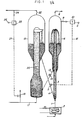
- FIG. 1 A conventional control scheme for a riser reactor FCC Unit is illustrated in Fig. 1.
- the oil feed which may be preheated by the heater 2 is passed via line 1 to the lower end of riser pipe 3.
- Heated catalyst from a stand-pipe 4 having a control valve 5 is combined with the heated oil in the riser 3 such that an oil-catalyst mixture rises in an ascending dispersed stream until it is discharged into reactor 6 wherein catalyst is separated as a dense bed 7.
- thee may be other fluidized contacting between oil and the catalyst particles within the relatively dense fluidized bed 7.
- a major portion of the necessary cracking and contact of the oil with the catalyst takes place in riser 3.
- Any catalyst particles remaining suspended in the vaporous cracked reaction products are separated at the upper end of reactor 6 by centrifugal or setler type means (not shown in Fig.1). Products are then transferred overhead via line 8 to a products recovery section (not shown) which includes at least one fractionator.
- a temperature sensing means 9, such as a thermocouple, is provided to sense the temperature within reactor 6 and to provide a signal to the temperature controller 10 indicative of the temperature at the top of the reactor 6.
- the temperature controller places a signal on a line 12 to adjust the valve 5 and thus adjust the temperature of the catalyst oil mixture in riser 3 in a direction to reduce the deviation of the measured temperature from the predetermined temperature as defined by the set point 11 of the controller 10.
- Spent catalyst from the bed 7 is continuously passed from reactor 6 by spent catalyst transfer line 13 equipped with a valve 14, and is passed to the lower portion of the regenerator 15 to form a relatively dense bed 16.
- Air is passed via air transfer line 17 equipped with a control valve 18 to the regenerator 15, where it passes through distributor grid 19 and serves to maintain bed 16 in a fluidized state and to pass catalyst continuously through the riser 20 as a dilute phase 21.
- flue gas is separated from regenerated catalyst, and exists via line 22.
- Regenerated catalyst is separated to form a relatively dense bed 23.
- the regeneratd catalyst bed 23 is at a substantially higher temperature than the spent catalyst from bed 7 by virtue of the coke burning which occurs in the regenerator 15.
- bed 23 and the flue gas in the chamber are substantially hotter than the spent but partially regenerated catalyst of bed 16.
- Valve 18 is commonly controlled by operator intervention to control the flow of air and thus the CO and oxygen content of the flue gas.
- the signal generated by composition sensor 24 is transmitted to the composition controller 25.
- Controller 25, equipped with set points 26, places a signal on line 27, which signal is indicative of the deviation of the carbon monoxide composition of the flue- gas from the set point 26, to adjust the control valve 18 in a direction to reduce the deviation of the measured composition from the predetermined composition as defined by the set point 26.
- the set point is adjusted to a CO content less than 2000 ppm and the flue gas, in general, will contain about 2% excess oxygen gas.
- valve 14 is usually coupled with valve 5 in such a manner as to maintain a fixed ratio of amount of catalyst in the regenerator 15 to amount of catalyst in the reactor 6.
- the present invention relates to the catalytic conversion of hydrocarbons with finely divided particles of catalyst. More particularly, the present invention is concerned with the conversion of hydrocarbons in a riser conversion zone under conditions promoting a more uniform mixing between hydrocarbon reactant and finely divided catalyst particles. In a more particular aspect the present invention is particularly concerned with the manner relied upon for injecting hydrocarbon feed into a stream of catalyst particles to form a suspension in a riser conversion zone.
- the catalytic cracking of hydrocarbons is practised at a temperature within the range of 900 o F. up to about 1200 0 F. with the temperature more usually restricted to less than 1100 o F.
- Operating pressures within the range of atmospheric up to 100 psig may be employed, it being preferred to select conditions assuring good catalyst circulation, product and reactant flow which will contribute to the overall economics of the operation.
- the hydrocarbon reactant is mixed with hot catalyst particles in the bottom of lower portion of the riser to form a suspension at a desired cracking temperature and the suspension is passed through the riser conversion zone under space velocity conditions providing a hydrocarbon residence time in the riser within the range of 1 to 15 seconds and more usually less than about 10 seconds.
- the suspension is discharged from the riser outlet into cyclonic separation zones or the suspension may be discharged from the riser into an enlarged zone wherein separation of catalyst particles from gasiform material such as hydrocarbon vapors is accomplished by a reduction in velocity thereby causing the catalyst particles to settle out.
- Cyclonic separating means may also be relied upon to remove particles of catalyst from vaporous material not removed by the reduced velocity.
- the hydrocarbon vapors are recovered and separated in a product fractionator.
- the catalyst particles are stripped to remove entrained hydrocarbons and the stripped catalyst may be passed to catalyst regeneration.
- each nozzle is related to substantially an equal cross-sectional area of the riser conversion zone.
- there are at least seven pipe nozzles terminating from a single oil feed inlet conduit at least 6 of the pipe nozzles form a ring spaced inwardly from the riser wall with the seventh concentrically located there within and the ring comprising the six nozzles will occupy an area which is at least 70% of the riser cross-sectional area.
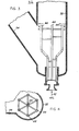
- FIG. 2 there is shown diagramatically a riser conversion zone 32, conduit means 34 for introducing catalyst to the bottom lower portion of riser 32, a separation zone 36 provided with a catalyst stripping zone 38 in the lower portion theeof and spent catalyst withdrawal conduit 40.
- Hydrocarbon feed introduced to the bottom of the riser 32 by conduit 42 is caused to pass upwardly through a plurality of distributing pipes 44 open at their upper end to form nozzles for dispersing hydrocarbon feed in contact with catalyst charged to the bottom of the riser by conduit 34 at an elevated cracking temperature of at least 900 o F.
- a suspension is formed with the dispersed and vaporized oil and catalyst which is then moved under selected velocity conditions upwardly through the riser.
- the suspension passing upwardly through the riser is discharged through slotted openings 46 in the upper extreme periphery of the riser 32 and into the enlarged separation zone above a dense fluid bed of catalyst 48.
- Vaporous products of conversion and stripping stream pass through cyclonic separators 50 provided with catalyst diplegs 52.
- separator 50 entrained catalyst particles are separated from vaporous material for return by dipleg 52 to bed 48.
- Separated vaporous material pass through conduits 54 to chamber 56 for withdrawal by conduit 58.
- Stripping gas such as steam is introduced to the bottom of bed 38 by conduit 60 and stripped catalyst is removed therefrom by conduit 40 for transfer to a catalyst regeneration zone shown in Fig.1.
- Fig.3 shows in greater detail the bottom portion of riser 32 and the multiple pipe inlet for injecting hydrocarbon feed into regenerated catalyst to form a suspension therewith for passage upwardly through riser 32.
- Fig.4 shows a cross-sectional view 4-4 of the pipe arrangement of Fig. 3 with open end nozzles for injecting hydrocarbon feed into the catalyst.
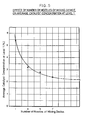
- the circle of pipes 44 preferably identify a cross-sectional area of the riser which is at least 70% of the riser cross-sectional area. Such an arrangement has been found to provide a more uniform catalyst density profile across the riser cross section than 5 or less feed injection pipes as depicted by the curve of Fig. 5.
- Level 1 referred to in the graph relates to measurements taken about 4 feet above the outlet of the pipe nozzles. It is clear from the graph that the seven pipe feed inlet device is better than a five and each of these are much better than a 1 or 3 pipe nozzle inlet arrangement.
- gasoline yield tuning factors used in a mathematical model simulation of the actual surveys. For example, in simulating each survey with a model, predicted gasoline yields had to be "tuned” donward to match the actual survey yields. The resulting adjustment (“gasoline delta”) represents the deviation of the actual selectivity observed in the survey from the inherent selectivity predicted by the model for that particular operation.
- Table 1 shows the actual reactor effluent yields for the three surveys. Before the surveys can be compared to determine the effect of feed preheat, yields had to be adjusted to the same feedstock, catalyst, and operating conditions, (except for preheat temperature). Election was made to adjust the two extreme preheat cases to the middle preheat case. Once the three surveys were adjusted to the same basis, any remaining differences in yields between them could be attributed to the changes in feed preheat temperature. These final adjusted survey yields are shown in Table 2.
- Maximum gasoline selectivity is obtained at the highest feed preheat temperature; it decreases gradually between 514 o F. and 374°F. and then decreases sharply between 374 0 F. and 265 0 F.
- Preheat temperatures according to the invention will generally be above 475 0 F, preferably about 500 o F. or higher, up to about 750-800°F.
Landscapes
- Chemical & Material Sciences (AREA)
- Engineering & Computer Science (AREA)
- Organic Chemistry (AREA)
- Chemical Kinetics & Catalysis (AREA)
- Oil, Petroleum & Natural Gas (AREA)
- Combustion & Propulsion (AREA)
- General Chemical & Material Sciences (AREA)
- Production Of Liquid Hydrocarbon Mixture For Refining Petroleum (AREA)
Applications Claiming Priority (2)
| Application Number | Priority Date | Filing Date | Title |
|---|---|---|---|
| US81494177A | 1977-07-12 | 1977-07-12 | |
| US814941 | 1977-07-12 |
Publications (1)
| Publication Number | Publication Date |
|---|---|
| EP0000433A1 true EP0000433A1 (fr) | 1979-01-24 |
Family
ID=25216409
Family Applications (1)
| Application Number | Title | Priority Date | Filing Date |
|---|---|---|---|
| EP78300121A Withdrawn EP0000433A1 (fr) | 1977-07-12 | 1978-07-06 | Procédé de craquage catalytique d'hydrocarbures en lit fluidisé |
Country Status (10)
| Country | Link |
|---|---|
| EP (1) | EP0000433A1 (fr) |
| JP (1) | JPS5418808A (fr) |
| AU (1) | AU524161B2 (fr) |
| BR (1) | BR7804460A (fr) |
| CA (1) | CA1112593A (fr) |
| DE (1) | DE2856971A1 (fr) |
| GB (1) | GB2040993B (fr) |
| IT (1) | IT1097236B (fr) |
| NL (1) | NL7815013A (fr) |
| ZA (1) | ZA783979B (fr) |
Cited By (5)
| Publication number | Priority date | Publication date | Assignee | Title |
|---|---|---|---|---|
| DE3223058A1 (de) * | 1981-06-23 | 1983-02-03 | Shell Internationale Research Maatschappij B.V., 2501 's-Gravenhage | Verfahren zum katalytischen cracken einer kohlenwasserstoffbeschickung in einer wirbelschicht |
| EP0227864A1 (fr) * | 1984-05-30 | 1987-07-08 | Mobil Oil Corporation | Appareillage d'injection de la charge dans un FCC et procédé FCC |
| US4800014A (en) * | 1983-12-02 | 1989-01-24 | Phillips Petroleum Company | Catalytic cracking process |
| US4808383A (en) * | 1985-05-30 | 1989-02-28 | Mobil Oil Corporation | FCC reactor multi-feed nozzle system |
| EP1343580A4 (fr) * | 2000-07-14 | 2006-02-01 | Exxonmobil Res & Eng Co | Systeme ameliore de craquage catalytique fluidise de molecules d'hydrocarbures |
Families Citing this family (3)
| Publication number | Priority date | Publication date | Assignee | Title |
|---|---|---|---|---|
| US4562046A (en) * | 1983-12-02 | 1985-12-31 | Phillips Petroleum Company | Catalytic cracking unit |
| US4555328A (en) * | 1984-01-19 | 1985-11-26 | Mobil Oil Corporation | Method and apparatus for injecting liquid hydrocarbon feed and steam into a catalytic cracking zone |
| DE3928699A1 (de) * | 1989-08-30 | 1991-03-14 | Walterscheid Gmbh Jean | Kupplungshaken fuer unterlenker |
Citations (4)
| Publication number | Priority date | Publication date | Assignee | Title |
|---|---|---|---|---|
| US3246960A (en) * | 1961-11-17 | 1966-04-19 | Humble Oil & Refining Company | Catalytic conversion apparatus |
| US3513087A (en) * | 1968-08-30 | 1970-05-19 | Continental Oil Co | Control system for fluid cat cracker |
| US3769203A (en) * | 1971-06-21 | 1973-10-30 | Mobil Oil Corp | Thermal energy control for a fcc system |
| FR2322195A1 (fr) * | 1975-08-27 | 1977-03-25 | Mobil Oil | Procede et appareil perfectionnes de commande de craquage catalytique fluide |
-
1978
- 1978-06-28 CA CA306,429A patent/CA1112593A/fr not_active Expired
- 1978-07-06 NL NL7815013A patent/NL7815013A/xx unknown
- 1978-07-06 GB GB7918901A patent/GB2040993B/en not_active Expired
- 1978-07-06 DE DE19782856971 patent/DE2856971A1/de not_active Withdrawn
- 1978-07-06 EP EP78300121A patent/EP0000433A1/fr not_active Withdrawn
- 1978-07-11 AU AU37936/78A patent/AU524161B2/en not_active Expired
- 1978-07-11 BR BR7804460A patent/BR7804460A/pt unknown
- 1978-07-12 IT IT25610/78A patent/IT1097236B/it active
- 1978-07-12 JP JP8414278A patent/JPS5418808A/ja active Pending
- 1978-07-12 ZA ZA783979A patent/ZA783979B/xx unknown
Patent Citations (4)
| Publication number | Priority date | Publication date | Assignee | Title |
|---|---|---|---|---|
| US3246960A (en) * | 1961-11-17 | 1966-04-19 | Humble Oil & Refining Company | Catalytic conversion apparatus |
| US3513087A (en) * | 1968-08-30 | 1970-05-19 | Continental Oil Co | Control system for fluid cat cracker |
| US3769203A (en) * | 1971-06-21 | 1973-10-30 | Mobil Oil Corp | Thermal energy control for a fcc system |
| FR2322195A1 (fr) * | 1975-08-27 | 1977-03-25 | Mobil Oil | Procede et appareil perfectionnes de commande de craquage catalytique fluide |
Cited By (5)
| Publication number | Priority date | Publication date | Assignee | Title |
|---|---|---|---|---|
| DE3223058A1 (de) * | 1981-06-23 | 1983-02-03 | Shell Internationale Research Maatschappij B.V., 2501 's-Gravenhage | Verfahren zum katalytischen cracken einer kohlenwasserstoffbeschickung in einer wirbelschicht |
| US4800014A (en) * | 1983-12-02 | 1989-01-24 | Phillips Petroleum Company | Catalytic cracking process |
| EP0227864A1 (fr) * | 1984-05-30 | 1987-07-08 | Mobil Oil Corporation | Appareillage d'injection de la charge dans un FCC et procédé FCC |
| US4808383A (en) * | 1985-05-30 | 1989-02-28 | Mobil Oil Corporation | FCC reactor multi-feed nozzle system |
| EP1343580A4 (fr) * | 2000-07-14 | 2006-02-01 | Exxonmobil Res & Eng Co | Systeme ameliore de craquage catalytique fluidise de molecules d'hydrocarbures |
Also Published As
| Publication number | Publication date |
|---|---|
| JPS5418808A (en) | 1979-02-13 |
| AU524161B2 (en) | 1982-09-02 |
| DE2856971A1 (de) | 1979-10-18 |
| GB2040993A (en) | 1980-09-03 |
| ZA783979B (en) | 1980-02-27 |
| IT1097236B (it) | 1985-08-26 |
| CA1112593A (fr) | 1981-11-17 |
| GB2040993B (en) | 1982-11-03 |
| IT7825610A0 (it) | 1978-07-12 |
| AU3793678A (en) | 1980-01-17 |
| NL7815013A (fr) | 1979-08-31 |
| BR7804460A (pt) | 1979-04-10 |
Similar Documents
| Publication | Publication Date | Title |
|---|---|---|
| US4385985A (en) | FCC Reactor with a downflow reactor riser | |
| US4419221A (en) | Cracking with short contact time and high temperatures | |
| US4411773A (en) | Heat balance in FCC process and apparatus with downflow reactor riser | |
| US7169293B2 (en) | Controllable space velocity reactor and process | |
| US4578183A (en) | Feed mixing technique for fluidized catalytic cracking of hydrocarbon oil | |
| EP0291253B1 (fr) | Procédé et appareillage pour mélanger la charge et le catalyseur dans un craquage catalytique fluidisé d'hydrocarbures | |
| US4448753A (en) | Apparatus for regenerating cracking catalyst | |
| US20080035526A1 (en) | Device for Contacting High Contaminated Feedstocks with Catalyst in an FCC Unit | |
| US3751359A (en) | Conversion of hydrocarbons | |
| US4036779A (en) | Method of regenerating catalyst in a swirl type regenerator containing a dilute phase baffle | |
| US3964876A (en) | Method and apparatus for catalytically cracking hydrocarbons | |
| CN107532090A (zh) | 流化焦化法 | |
| US4523987A (en) | Feed mixing techique for fluidized catalytic cracking of hydrocarbon oil | |
| EP0315180B1 (fr) | Procédé et dispositif de séparation liquide-solide | |
| CA1055915A (fr) | Methode et systeme de regeneration de catalyseurs fluidisables | |
| US4026789A (en) | Method for catalytically cracking hydrocarbons | |
| US4820493A (en) | Apparatus for mixing fluid catalytic cracking hydrocarbon feed and catalyst | |
| US4664889A (en) | Apparatus for separating hydrocarbon products from catalyst particles | |
| EP0000433A1 (fr) | Procédé de craquage catalytique d'hydrocarbures en lit fluidisé | |
| KR100493753B1 (ko) | 조절된촉매상에공급원료를적당한각도로주입함으로써하강식으로접촉분해하는방법및장치 | |
| US3129060A (en) | Control of conversion in a catalytic hydrogen producing unit | |
| US2883332A (en) | Conversion process and apparatus with plural stages and intermediate stripping zone | |
| US4430201A (en) | Regeneration of fluidizable catalyst | |
| EP0593823A1 (fr) | Séparation et trempe d'une décharge d'un tuyau montant d'un système FCC | |
| US4428822A (en) | Fluid catalytic cracking |
Legal Events
| Date | Code | Title | Description |
|---|---|---|---|
| PUAI | Public reference made under article 153(3) epc to a published international application that has entered the european phase |
Free format text: ORIGINAL CODE: 0009012 |
|
| AK | Designated contracting states |
Designated state(s): DE GB NL |
|
| STAA | Information on the status of an ep patent application or granted ep patent |
Free format text: STATUS: THE APPLICATION IS DEEMED TO BE WITHDRAWN |
|
| 18D | Application deemed to be withdrawn | ||
| 32 | Conversion | ||
| RIN1 | Information on inventor provided before grant (corrected) |
Inventor name: DAVIS, FRANCIS EARLE |