EP0593823A1 - Séparation et trempe d'une décharge d'un tuyau montant d'un système FCC - Google Patents
Séparation et trempe d'une décharge d'un tuyau montant d'un système FCC Download PDFInfo
- Publication number
- EP0593823A1 EP0593823A1 EP92309525A EP92309525A EP0593823A1 EP 0593823 A1 EP0593823 A1 EP 0593823A1 EP 92309525 A EP92309525 A EP 92309525A EP 92309525 A EP92309525 A EP 92309525A EP 0593823 A1 EP0593823 A1 EP 0593823A1
- Authority
- EP
- European Patent Office
- Prior art keywords
- catalyst
- hydrocarbon
- mixture
- temperature
- process according
- Prior art date
- Legal status (The legal status is an assumption and is not a legal conclusion. Google has not performed a legal analysis and makes no representation as to the accuracy of the status listed.)
- Granted
Links
Images

Classifications
-
- C—CHEMISTRY; METALLURGY
- C10—PETROLEUM, GAS OR COKE INDUSTRIES; TECHNICAL GASES CONTAINING CARBON MONOXIDE; FUELS; LUBRICANTS; PEAT
- C10G—CRACKING HYDROCARBON OILS; PRODUCTION OF LIQUID HYDROCARBON MIXTURES, e.g. BY DESTRUCTIVE HYDROGENATION, OLIGOMERISATION, POLYMERISATION; RECOVERY OF HYDROCARBON OILS FROM OIL-SHALE, OIL-SAND, OR GASES; REFINING MIXTURES MAINLY CONSISTING OF HYDROCARBONS; REFORMING OF NAPHTHA; MINERAL WAXES
- C10G11/00—Catalytic cracking, in the absence of hydrogen, of hydrocarbon oils
- C10G11/14—Catalytic cracking, in the absence of hydrogen, of hydrocarbon oils with preheated moving solid catalysts
- C10G11/18—Catalytic cracking, in the absence of hydrogen, of hydrocarbon oils with preheated moving solid catalysts according to the "fluidised-bed" technique
Definitions
- the invention is a process and apparatus for the separation of a catalyst phase from a cracked hydrocarbon phase in the fluid catalyst cracking (FCC) of hydrocarbon. More particularly, the invention is a process and apparatus to reduce post riser cracking of cracked hydrocarbon discharged from a riser reactor. The invention is also a process and apparatus which heat integrates the riser reactor, and the catalyst regenerator, thereby reducing the heat duty in a fluid catalyst cracking (FCC) process.
- FCC fluid catalyst cracking
- Fluid catalytic cracking (FCC) processes are known in the art. State of the art commercial catalytic cracking catalysts for these processes are highly active and selective for converting hydrocarbon charge stocks to liquid fuel products. With such active catalysts it is preferable to conduct catalytic cracking reactions in a dilute phase transport type reaction system with a relatively short period of contact between the catalyst and the hydrocarbon feedstock, e.g. 0.2 to 10 seconds.
- catalytic cracking systems have been developed in which the primary cracking reaction is carried out in a transfer line reactor or riser reactor.
- the catalyst is dispersed in the hydrocarbon feedstock and passed through an elongated reaction zone at relatively high velocity.
- feedstock acts as a carrier for the catalyst.
- the hydrocarbon vapors move with sufficient velocity as to maintain the catalyst particles in suspension with a minimum of back mixing of the catalyst particles with the gaseous carrier.
- the cracking reactions are conveniently carried out in high velocity transport line reactors wherein the catalyst is moved from one vessel to another by the hydrocarbon vapors.
- Such reactors have become known in the art as risers or riser reactors.
- the catalyst and hydrocarbon mixture passes from the transfer line reactor into a first separation zone in which hydrocarbon vapors are separated from the catalyst.
- the catalyst particles are then passed into a second separation zone, usually a dense fluidized bed stripping zone wherein further separation of hydrocarbons from the catalyst takes place by stripping the catalyst with steam.
- the catalyst is introduced into a regeneration zone where carbonaceous residues are removed by burning with air or other oxygen-containing gas. After regeneration, hot catalyst from the regeneration zone is reintroduced into the transfer line reactor with fresh hydrocarbon feed.
- U.S. Patent 4,664,888 to L. F. Castagnos, Jr. teaches a rough cut catalyst-vapor separator in a fluid catalytic cracking process.
- a separator surface causes the oil-catalyst mixture to undergo a 180° turn.
- Catalyst moves toward the separator surface to form a catalytic phase.
- Vapor is squeezed away from the wall forming a vapor phase.
- a shave edge maintains the separation.
- U.S. Patents 4,764,268 and 4,624,771 both to P. A. Lane teach a fluid catalytic cracking process.
- a quench fluid is passed into a downstream portion of the riser reactor in the last 10 vol% to prevent overcracking of hydrocarbon products.
- the quench fluid is inert to cracking, e.g. water, steam or a selected hydrocarbon.
- the catalyst and vapor are separated after quenching. An advantageous yield of product of a desirable octane number is achieved.
- the nozzles form a flat fan-shaped fluid sheet.
- the included angle of the fan is from 10 deg. to 130 deg. in standard nozzles and capacities range from 0.38 to 75.7 litres/minute (0.1 to 20 gal./minute).
- the invention is an improvement in a fluid catalytic cracking (FCC) process.
- FCC fluid catalytic cracking
- a hydrocarbon feedstock in suspension with a fluidized catalyst is cracked at catalytic reaction temperature to form a mixture of cracked hydrocarbon and spent catalyst.
- the mixture is separated into separated cracked hydrocarbon and spent catalyst phases.
- the improvement comprises quenching the separated cracked hydrocarbon to an unreactive temperature substantially simultaneously with separating the two phases.
- the quenching of the separated cracked hydrocarbon is carried out in the absence of quenching spent catalyst.
- the absence of quenching spent catalyst results in a reduction in heat duty in the catalyst regenerator where carbonaceous matter is burned from the catalyst.
- Fig. 1 is a diagrammatic arrangement of a fluid catalytic cracking process comprising a riser reactor, catalyst separator, reactor vessel and catalyst regenerator.
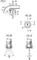
- Fig. 2 is a schematic side view of a separator/quench apparatus.
- Fig. 3A is an end elevation of a fan nozzle.
- Fig. 3B is a longitudinal section through a fan nozzle showing a first spray configuration.
- Fig. 3C is a longitudinal section through a fan nozzle showing a second spray configuration.
- Fig. 1 is representative of an apparatus for contacting a hydrocarbon feedstock with finely divided fluidized catalyst in riser reactor 40 at catalytic cracking conditions.
- a clean, freshly regenerated catalyst is delivered from regenerated catalyst standpipe 270 into the lower portion of riser reactor 40.
- the regenerated catalyst has a carbon content less than about 0.1 wt% and an ASTM microactivity of 60 to 70.
- As the catalyst entersthe riser its temperature decreases from 760°C to 700°C by the addition of a fluidization medium delivered by line 20.
- the fluidization medium may be steam, nitrogen or low molecular weight hydrocarbons such as methane, ethane, ethylene or fuel gas.
- the amount of fluidization medium must be sufficient to fluidize the fluid zeolite catalyst in the base of riser 40 above the minimum fluidization velocity to move the catalyst toward the injection point of the hydrocarbon oil.
- a liquid feedstock such as vacuum gas oil, atmospheric residuum, deasphalted oil or combinations thereof, having a boiling range of about 200°C to 540°C, is heated and delivered to riser reactor 40 through conduit 30.
- the feedstock enters the riser by way of an injection nozzle (not shown) which may be a single nozzle or an arrangement of more than one nozzle which mixes oil and catalyst quickly and completely after injection.
- the amount of catalyst circulated must be enough to completely vaporize the oil and be sufficient to crack the feedstock to a slate of products which when corrected to room temperature include gases, low boiling liquids and fuel boiling range liquids such as gasoline and light cycle gas oil.
- gases, low boiling liquids and fuel boiling range liquids such as gasoline and light cycle gas oil.
- the mixture of products and unconverted gas oil vapor have sufficient velocity to transport the fluid catalyst upwardly through the riser 40.
- the riser conversion zone comprises the internal volume of the riser from the lower injection point to separator/quencher 50 including transitional conduit 49 and discharge conduit 52.
- Separator/quencher 50 is close coupled with riser 40 so that all of the reaction mixture from the riser reactor flows into it.
- Separated hydrocarbon vapor passes into reactor vessel 120. From there, hydrocarbon vapor passes into secondary cyclone 110, plenum 121 and is transported through conduit 125 to fractionation and purification means (not shown).
- Separated catalyst from separator/quencher 50 and catalyst from secondary cyclone 110 falls to a lower portion of the reactor vessel 120 through dipleg 111.
- the dipleg is sealed by means such as J-valves, trickle valves, flapper valves (not shown).
- the catalyst flows into the stripping zone 130 containing baffles 135 or other means to contact the catalyst and stripping gas.
- the stripping gas may be nitrogen, steam or other suitable material delivered by conduit 160 to distributor 161.
- Distributor 161 uniformly disperses the stripping gas into the stripping zone 130 and removes volatile and volatizable hydrocarbons.
- a hotter catalyst temperature in stripping zone 30 increases the amount of hydrocarbon volatized and stripped from the catalyst.
- the hydrocarbons stripped from the catalyst and stripping gas flow out of reactor vessel 120 with the product vapors through secondary cyclone separator 110, plenum 121 and conduit 125.
- the stripped catalyst leaves stripping zone 130 and is delivered to the regenerator 250 by way of spent catalyst standpipe 165.
- the regenerator 250 contains a lower dense phase bed of catalyst and an upper dilute phase of catalyst. Catalyst is uniformly distributed across the upper surface of the dense phase bed. Most of the coke is removed in the dense phase bed.
- a combustion medium of air or oxygen and nitrogen is delivered by conduit 260 to a distribution device 261 to mix combustion medium and coked catalyst. Coke is burned from the catalyst to give a flue gas containing amounts of CO2, SO2, and NO x .
- the combustion of the coke to CO2 is preferably carried out at a regenerator temperature above about 650°C and below about 760°C in the presence of a combustion promoter such as platinum residing on the catalyst so that 0.1 wt% or less residual carbon is left on the catalyst.
- the flue gas passes through the regenerator dilute phase, cyclone 225, plenum 226 and flue gas line 227 for further processing.
- catalyst is separated and returned to the dense bed by way of dipleg 228.
- the regenerated catalyst flows from the dense bed to standpipe 270.
- Slide valve 275 regulates the flow of regenerated catalyst from standpipe 270 to riser 40.
- FIG. 2 a schematic representation of separator/quencher 50.
- a catalyst and cracked hydrocarbon mixture flows through discharge conduit 52 which directs the mixture toward centrifugal separator wall 54.
- Centrifugal separator wall 54 is geometrically described by one-quarter of a circle in the vertical plane parallel to the surface of the paper. The radius of the circle is substantially larger than the radius of discharge conduit 52. The center of the circle is point 55. In this representation, the radius is approximately five times the radius of discharge conduit 52.
- This relatively large axis of rotation causes a deflection of the mixture from flow in the horizontal direction to downward flow. This change in direction also causes the centrifugal disengagement or separation of the streaminto a downwardly flowing predominantly catalyst phase which is in contact with wall 54 and a predominantly cracked vapor phase, spaced from the wall 54.
- Quench fluid is introduced via quench line 57 and valve 58 into separator/quencher 50.
- the quench fluid is discharged into the predominately cracked vapor phase by means of nozzle 60.
- Figs. 3A, 3B and 3C are three views of nozzle 60 and the spray pattern of quench fluid it produces in separator/quencher 50.
- the spray pattern is critical to the invention. Substantially all of the quench fluid spray must remain in the cracked vapor phase and not cross into the catalyst phase before the quench fluid is vaporized. Nozzles which produce such a spray pattern are commercially available. Fish tail nozzles and fan nozzles produce a relatively flat sheet or flat ellipse of spray which is well defined. The spray is so well defined that the nozzle is selected for the exact spray angle in both dimensions.
- a fan nozzle produces a flat sheet of spray in an elliptical spray pattern.
- the sheet becomes thinner with distance from the nozzle.
- Surface tension causes the thin sheets to break up into droplets at a distance from the nozzle.
- Fan nozzles which produce spray angles of 10° to 110° are commercially available. It is characteristic of fan nozzles that sheets of very uniform thickness are formed at included angles of 50° to 10°. At larger included angles two separate streams called horns are produced with liquid sheets connecting the horns. These horns have much less surface area than the sheets and may remain in the liquid state long enough to contact hot catalyst, which is undesirable because of quenching.
- the nozzles which produce more uniform sheets of quench fluid also produce the narrow pattern required to avoid impingement of the catalyst phase with quench fluid.
- the fan nozzle is therefore oriented so that the long axis of the ellipse is perpendicular to the cracked hydrocarbon-catalyst interface.
- the short axis is perpendicular with the interface.
- the long axis has an included angle 62 of 50° in Fig. 3B.
- the short axis has an included angle 64 of 10° in Fig. 3C.
- the most desirable products are debutanized naphtha with an end point about 220°C (gasoline) and light cycle gas oil boiling from 220°C to about 355°C.
- the highest yield of these fractions is achieved by cracking at fluid catalytic cracking conditions at a temperature in the range 480°C to 590°C, preferably 510°C to 540°C for 0.5 to 1.5 seconds and then terminating the cracking reaction at the riser outlet.
- the cracking reaction is terminated at temperatures of about 500°C and less defined herein as an unreactive temperature.
- the yield of the most desirable products decreases. The decrease in desirable products is attributed to an increase in the dry (hydrocarbon) gas make.
- This invention is shown by way of example.
Landscapes
- Chemical & Material Sciences (AREA)
- Oil, Petroleum & Natural Gas (AREA)
- Engineering & Computer Science (AREA)
- Chemical Kinetics & Catalysis (AREA)
- General Chemical & Material Sciences (AREA)
- Organic Chemistry (AREA)
- Production Of Liquid Hydrocarbon Mixture For Refining Petroleum (AREA)
Priority Applications (6)
| Application Number | Priority Date | Filing Date | Title |
|---|---|---|---|
| US07/620,180 US5217602A (en) | 1990-11-30 | 1990-11-30 | FCC riser discharge separation and quench |
| US07/910,798 US5288920A (en) | 1990-11-30 | 1992-07-09 | FCC riser discharge separation and quench apparatus |
| CA002079011A CA2079011A1 (fr) | 1990-11-30 | 1992-09-24 | Separation de l'effluent d'un reacteur de craquage catalytique fluide et refroidissement des hydrocarbures separes |
| EP92309525A EP0593823B1 (fr) | 1990-11-30 | 1992-10-19 | Séparation et trempe d'une décharge d'un tuyau montant d'un système FCC |
| DE69221305T DE69221305D1 (de) | 1992-10-19 | 1992-10-19 | Trennung und Abschreckung eines Abflusses einem FCC-Steigrohr |
| JP4312686A JPH06200259A (ja) | 1990-11-30 | 1992-10-29 | 流動接触分解法及びそのための装置 |
Applications Claiming Priority (5)
| Application Number | Priority Date | Filing Date | Title |
|---|---|---|---|
| US07/620,180 US5217602A (en) | 1990-11-30 | 1990-11-30 | FCC riser discharge separation and quench |
| US07/910,798 US5288920A (en) | 1990-11-30 | 1992-07-09 | FCC riser discharge separation and quench apparatus |
| CA002079011A CA2079011A1 (fr) | 1990-11-30 | 1992-09-24 | Separation de l'effluent d'un reacteur de craquage catalytique fluide et refroidissement des hydrocarbures separes |
| EP92309525A EP0593823B1 (fr) | 1990-11-30 | 1992-10-19 | Séparation et trempe d'une décharge d'un tuyau montant d'un système FCC |
| JP4312686A JPH06200259A (ja) | 1990-11-30 | 1992-10-29 | 流動接触分解法及びそのための装置 |
Publications (2)
| Publication Number | Publication Date |
|---|---|
| EP0593823A1 true EP0593823A1 (fr) | 1994-04-27 |
| EP0593823B1 EP0593823B1 (fr) | 1997-07-30 |
Family
ID=27508471
Family Applications (1)
| Application Number | Title | Priority Date | Filing Date |
|---|---|---|---|
| EP92309525A Expired - Lifetime EP0593823B1 (fr) | 1990-11-30 | 1992-10-19 | Séparation et trempe d'une décharge d'un tuyau montant d'un système FCC |
Country Status (4)
| Country | Link |
|---|---|
| US (1) | US5288920A (fr) |
| EP (1) | EP0593823B1 (fr) |
| JP (1) | JPH06200259A (fr) |
| CA (1) | CA2079011A1 (fr) |
Cited By (3)
| Publication number | Priority date | Publication date | Assignee | Title |
|---|---|---|---|---|
| US7347930B2 (en) | 2003-10-16 | 2008-03-25 | China Petroleum & Chemical Corporation | Process for cracking hydrocarbon oils |
| US7435332B2 (en) | 2003-09-28 | 2008-10-14 | China Petroleum & Chemical Corporation | Process for cracking hydrocarbon oils |
| US7678342B1 (en) | 1999-04-23 | 2010-03-16 | China Petrochemical Corporation | Riser reactor for fluidized catalytic conversion |
Families Citing this family (11)
| Publication number | Priority date | Publication date | Assignee | Title |
|---|---|---|---|---|
| US5234578A (en) | 1988-08-26 | 1993-08-10 | Uop | Fluidized catalytic cracking process utilizing a high temperature reactor |
| US5662868A (en) * | 1994-09-22 | 1997-09-02 | Stone & Webster Engineering Corporation | Short residence time cracking apparatus and process |
| US5723040A (en) * | 1994-09-22 | 1998-03-03 | Stone & Webster Engineering Corporation | Fluid catalytic cracking process and apparatus |
| JP2925963B2 (ja) * | 1994-12-05 | 1999-07-28 | 石油公団 | メタンの酸化カップリング方法とその装置 |
| US5554341A (en) * | 1994-12-12 | 1996-09-10 | Phillips Petroleum Company | Feed zone performance for a cat cracker |
| JP3553311B2 (ja) * | 1997-03-14 | 2004-08-11 | 財団法人石油産業活性化センター | 炭化水素油の接触分解方法 |
| US8246914B2 (en) * | 2008-12-22 | 2012-08-21 | Uop Llc | Fluid catalytic cracking system |
| US9687765B2 (en) * | 2012-10-31 | 2017-06-27 | Dow Global Technologies Llc | Process and apparatus for minimizing attrition of catalyst particles |
| WO2017053815A1 (fr) | 2015-09-25 | 2017-03-30 | Inaeris Technologies, Llc | Ajout d'un catalyseur à un réacteur en lit fluidisé circulant |
| US10563129B2 (en) | 2015-09-25 | 2020-02-18 | Inaeris Technologies, Llc | Use of cooling media in biomass conversion process |
| CN114072372A (zh) | 2019-06-28 | 2022-02-18 | 陶氏环球技术有限责任公司 | 包括使用冷却的产物作为再循环的骤冷流的形成轻质烯烃的方法 |
Citations (3)
| Publication number | Priority date | Publication date | Assignee | Title |
|---|---|---|---|---|
| US4764268A (en) * | 1987-04-27 | 1988-08-16 | Texaco Inc. | Fluid catalytic cracking of vacuum gas oil with a refractory fluid quench |
| EP0448860A1 (fr) * | 1990-03-26 | 1991-10-02 | Amoco Corporation | Craquage catalytique avec trempe |
| US5073249A (en) * | 1989-11-21 | 1991-12-17 | Mobil Oil Corporation | Heavy oil catalytic cracking process and apparatus |
Family Cites Families (13)
| Publication number | Priority date | Publication date | Assignee | Title |
|---|---|---|---|---|
| US1151258A (en) * | 1911-01-12 | 1915-08-24 | Schutte & Koerting Co | Oil-burner. |
| US2793173A (en) * | 1955-03-15 | 1957-05-21 | Exxon Research Engineering Co | Prevention of coke deposits in fluid cokers |
| US2906695A (en) * | 1956-08-07 | 1959-09-29 | Exxon Research Engineering Co | High temperature short time hydrocarbon conversion process |
| US2943994A (en) * | 1958-02-14 | 1960-07-05 | Exxon Research Engineering Co | Chemicals coking quenching system |
| NL108360C (fr) * | 1958-02-26 | |||
| US3133014A (en) * | 1960-12-30 | 1964-05-12 | Air Prod & Chem | Quench system for synthetic crude |
| US3174924A (en) * | 1962-06-04 | 1965-03-23 | Phillips Petroleum Co | Quench method and apparatus |
| US3322647A (en) * | 1964-07-27 | 1967-05-30 | Monsanto Co | Quenching apparatus |
| US3663645A (en) * | 1970-02-02 | 1972-05-16 | Lummus Co | Liquid quench |
| GB2051619A (en) * | 1979-07-02 | 1981-01-21 | Shell Int Research | Separation of gases from particle streams |
| US4664888A (en) * | 1985-06-27 | 1987-05-12 | Texaco Inc. | Fluid catalytic cracking catalyst-vapor separator |
| US5089235A (en) * | 1990-03-26 | 1992-02-18 | Amoco Corporation | Catalytic cracking unit with external cyclone and oil quench system |
| US5087427A (en) * | 1990-03-26 | 1992-02-11 | Amoco Corporation | Catalytic cracking unit with internal gross cut separator and quench injector |
-
1992
- 1992-07-09 US US07/910,798 patent/US5288920A/en not_active Expired - Lifetime
- 1992-09-24 CA CA002079011A patent/CA2079011A1/fr not_active Abandoned
- 1992-10-19 EP EP92309525A patent/EP0593823B1/fr not_active Expired - Lifetime
- 1992-10-29 JP JP4312686A patent/JPH06200259A/ja active Pending
Patent Citations (3)
| Publication number | Priority date | Publication date | Assignee | Title |
|---|---|---|---|---|
| US4764268A (en) * | 1987-04-27 | 1988-08-16 | Texaco Inc. | Fluid catalytic cracking of vacuum gas oil with a refractory fluid quench |
| US5073249A (en) * | 1989-11-21 | 1991-12-17 | Mobil Oil Corporation | Heavy oil catalytic cracking process and apparatus |
| EP0448860A1 (fr) * | 1990-03-26 | 1991-10-02 | Amoco Corporation | Craquage catalytique avec trempe |
Cited By (4)
| Publication number | Priority date | Publication date | Assignee | Title |
|---|---|---|---|---|
| US7678342B1 (en) | 1999-04-23 | 2010-03-16 | China Petrochemical Corporation | Riser reactor for fluidized catalytic conversion |
| US7435332B2 (en) | 2003-09-28 | 2008-10-14 | China Petroleum & Chemical Corporation | Process for cracking hydrocarbon oils |
| US7347930B2 (en) | 2003-10-16 | 2008-03-25 | China Petroleum & Chemical Corporation | Process for cracking hydrocarbon oils |
| US9163182B2 (en) | 2003-10-16 | 2015-10-20 | China Petroleum & Chemical Corporation | Process for cracking hydrocarbon oils |
Also Published As
| Publication number | Publication date |
|---|---|
| US5288920A (en) | 1994-02-22 |
| CA2079011A1 (fr) | 1994-03-25 |
| EP0593823B1 (fr) | 1997-07-30 |
| JPH06200259A (ja) | 1994-07-19 |
Similar Documents
| Publication | Publication Date | Title |
|---|---|---|
| US4789458A (en) | Fluid catalytic cracking with plurality of catalyst stripping zones | |
| US4332674A (en) | Method and apparatus for cracking residual oils | |
| US4985136A (en) | Ultra-short contact time fluidized catalytic cracking process | |
| US4419221A (en) | Cracking with short contact time and high temperatures | |
| EP1558372B1 (fr) | Procede de craquage catalytique profond ameliore | |
| US4917790A (en) | Heavy oil catalytic cracking process and apparatus | |
| US4051013A (en) | Fluid catalytic cracking process for upgrading a gasoline-range feed | |
| US6616900B1 (en) | FCC process with two zone short contact time reaction conduit | |
| KR101344182B1 (ko) | 통합된 기체/고체 분리 시스템을 갖는 2개의 유동 반응구역을 구비한 신규한 반응기 | |
| US4764268A (en) | Fluid catalytic cracking of vacuum gas oil with a refractory fluid quench | |
| EP0753037B1 (fr) | Procede et appareil permettant de produire des olefines legeres | |
| CA2052709C (fr) | Appareil d'enlevement du gaz de stripper d'un caisson de reacteur d'unite de craquage sur lit fluidise | |
| US5032252A (en) | Process and apparatus for hot catalyst stripping in a bubbling bed catalyst regenerator | |
| US4601814A (en) | Method and apparatus for cracking residual oils | |
| US20080035526A1 (en) | Device for Contacting High Contaminated Feedstocks with Catalyst in an FCC Unit | |
| US5128109A (en) | Heavy oil catalytic cracking apparatus | |
| EP0419639A1 (fr) | Procede et appareil catalytiques de craquage d'huiles lourdes | |
| US5288920A (en) | FCC riser discharge separation and quench apparatus | |
| CA1055915A (fr) | Methode et systeme de regeneration de catalyseurs fluidisables | |
| US5183558A (en) | Heavy oil catalytic cracking process and apparatus | |
| US5217602A (en) | FCC riser discharge separation and quench | |
| US20140004018A1 (en) | Process and apparatus for distributing hydrocarbon feed to a catalyst stream | |
| US5308473A (en) | Low NOx FCC regeneration process and apparatus | |
| US5043055A (en) | Process and apparatus for hot catalyst stripping above a bubbling bed catalyst regenerator | |
| WO1994017156A1 (fr) | Craquage catalytique fluidise |
Legal Events
| Date | Code | Title | Description |
|---|---|---|---|
| PUAI | Public reference made under article 153(3) epc to a published international application that has entered the european phase |
Free format text: ORIGINAL CODE: 0009012 |
|
| AK | Designated contracting states |
Kind code of ref document: A1 Designated state(s): DE GB IT NL |
|
| 17P | Request for examination filed |
Effective date: 19940926 |
|
| 17Q | First examination report despatched |
Effective date: 19951116 |
|
| GRAG | Despatch of communication of intention to grant |
Free format text: ORIGINAL CODE: EPIDOS AGRA |
|
| GRAH | Despatch of communication of intention to grant a patent |
Free format text: ORIGINAL CODE: EPIDOS IGRA |
|
| RAP1 | Party data changed (applicant data changed or rights of an application transferred) |
Owner name: ABB LUMMUS GLOBAL INC. |
|
| GRAH | Despatch of communication of intention to grant a patent |
Free format text: ORIGINAL CODE: EPIDOS IGRA |
|
| GRAA | (expected) grant |
Free format text: ORIGINAL CODE: 0009210 |
|
| AK | Designated contracting states |
Kind code of ref document: B1 Designated state(s): DE GB IT NL |
|
| PG25 | Lapsed in a contracting state [announced via postgrant information from national office to epo] |
Ref country code: NL Free format text: LAPSE BECAUSE OF FAILURE TO SUBMIT A TRANSLATION OF THE DESCRIPTION OR TO PAY THE FEE WITHIN THE PRESCRIBED TIME-LIMIT Effective date: 19970730 Ref country code: IT Free format text: LAPSE BECAUSE OF FAILURE TO SUBMIT A TRANSLATION OF THE DESCRIPTION OR TO PAY THE FEE WITHIN THE PRE;WARNING: LAPSES OF ITALIAN PATENTS WITH EFFECTIVE DATE BEFORE 2007 MAY HAVE OCCURRED AT ANY TIME BEFORE 2007. THE CORRECT EFFECTIVE DATE MAY BE DIFFERENT FROM THE ONE RECORDED.SCRIBED TIME-LIMIT Effective date: 19970730 |
|
| REF | Corresponds to: |
Ref document number: 69221305 Country of ref document: DE Date of ref document: 19970904 |
|
| PG25 | Lapsed in a contracting state [announced via postgrant information from national office to epo] |
Ref country code: DE Effective date: 19971031 |
|
| NLV1 | Nl: lapsed or annulled due to failure to fulfill the requirements of art. 29p and 29m of the patents act | ||
| PLBE | No opposition filed within time limit |
Free format text: ORIGINAL CODE: 0009261 |
|
| 26N | No opposition filed | ||
| PGFP | Annual fee paid to national office [announced via postgrant information from national office to epo] |
Ref country code: GB Payment date: 19981002 Year of fee payment: 7 |
|
| PG25 | Lapsed in a contracting state [announced via postgrant information from national office to epo] |
Ref country code: GB Free format text: LAPSE BECAUSE OF NON-PAYMENT OF DUE FEES Effective date: 19991019 |
|
| GBPC | Gb: european patent ceased through non-payment of renewal fee |
Effective date: 19991019 |