EP0000450B1 - Appareils de reproduction photographique de documents transparents, notamment du type agrandisseur photographique - Google Patents
Appareils de reproduction photographique de documents transparents, notamment du type agrandisseur photographique Download PDFInfo
- Publication number
- EP0000450B1 EP0000450B1 EP78400010A EP78400010A EP0000450B1 EP 0000450 B1 EP0000450 B1 EP 0000450B1 EP 78400010 A EP78400010 A EP 78400010A EP 78400010 A EP78400010 A EP 78400010A EP 0000450 B1 EP0000450 B1 EP 0000450B1
- Authority
- EP
- European Patent Office
- Prior art keywords
- source
- plane
- screen
- comprised
- image
- Prior art date
- Legal status (The legal status is an assumption and is not a legal conclusion. Google has not performed a legal analysis and makes no representation as to the accuracy of the status listed.)
- Expired
Links
- 210000001747 pupil Anatomy 0.000 claims description 34
- 238000005286 illumination Methods 0.000 claims description 21
- 239000011521 glass Substances 0.000 claims description 14
- 229910052724 xenon Inorganic materials 0.000 claims description 14
- FHNFHKCVQCLJFQ-UHFFFAOYSA-N xenon atom Chemical compound [Xe] FHNFHKCVQCLJFQ-UHFFFAOYSA-N 0.000 claims description 14
- 230000005499 meniscus Effects 0.000 claims description 13
- 239000005338 frosted glass Substances 0.000 claims description 11
- 230000004075 alteration Effects 0.000 claims description 6
- 241000282326 Felis catus Species 0.000 claims description 3
- CETPSERCERDGAM-UHFFFAOYSA-N ceric oxide Chemical compound O=[Ce]=O CETPSERCERDGAM-UHFFFAOYSA-N 0.000 claims description 3
- 230000000694 effects Effects 0.000 claims description 3
- 210000000887 face Anatomy 0.000 claims description 3
- 239000003086 colorant Substances 0.000 claims description 2
- 239000006185 dispersion Substances 0.000 claims description 2
- 238000001228 spectrum Methods 0.000 claims 1
- 230000033458 reproduction Effects 0.000 description 16
- 230000003287 optical effect Effects 0.000 description 12
- 238000012937 correction Methods 0.000 description 10
- 230000002745 absorbent Effects 0.000 description 4
- 239000002250 absorbent Substances 0.000 description 4
- 210000004027 cell Anatomy 0.000 description 4
- 238000000151 deposition Methods 0.000 description 4
- 238000009826 distribution Methods 0.000 description 4
- 238000004519 manufacturing process Methods 0.000 description 3
- 238000007639 printing Methods 0.000 description 3
- 238000010521 absorption reaction Methods 0.000 description 2
- 230000005540 biological transmission Effects 0.000 description 2
- 238000001816 cooling Methods 0.000 description 2
- 230000007547 defect Effects 0.000 description 2
- 230000008021 deposition Effects 0.000 description 2
- 238000010586 diagram Methods 0.000 description 2
- 238000006073 displacement reaction Methods 0.000 description 2
- 239000004926 polymethyl methacrylate Substances 0.000 description 2
- 229920005440 Altuglas® Polymers 0.000 description 1
- 241001644893 Entandrophragma utile Species 0.000 description 1
- 108010010803 Gelatin Proteins 0.000 description 1
- 201000009310 astigmatism Diseases 0.000 description 1
- 230000002238 attenuated effect Effects 0.000 description 1
- 210000000481 breast Anatomy 0.000 description 1
- 230000008859 change Effects 0.000 description 1
- 230000021615 conjugation Effects 0.000 description 1
- 239000000470 constituent Substances 0.000 description 1
- 238000010276 construction Methods 0.000 description 1
- 229920000159 gelatin Polymers 0.000 description 1
- 239000008273 gelatin Substances 0.000 description 1
- 235000019322 gelatine Nutrition 0.000 description 1
- 235000011852 gelatine desserts Nutrition 0.000 description 1
- 239000005337 ground glass Substances 0.000 description 1
- 230000036541 health Effects 0.000 description 1
- 238000009434 installation Methods 0.000 description 1
- 238000005259 measurement Methods 0.000 description 1
- 238000000034 method Methods 0.000 description 1
- 239000013307 optical fiber Substances 0.000 description 1
- 229920003229 poly(methyl methacrylate) Polymers 0.000 description 1
- 230000008569 process Effects 0.000 description 1
- 238000011084 recovery Methods 0.000 description 1
- 230000001850 reproductive effect Effects 0.000 description 1
- 239000007787 solid Substances 0.000 description 1
- 238000001771 vacuum deposition Methods 0.000 description 1
- 238000004804 winding Methods 0.000 description 1
Images



Classifications
-
- G—PHYSICS
- G03—PHOTOGRAPHY; CINEMATOGRAPHY; ANALOGOUS TECHNIQUES USING WAVES OTHER THAN OPTICAL WAVES; ELECTROGRAPHY; HOLOGRAPHY
- G03B—APPARATUS OR ARRANGEMENTS FOR TAKING PHOTOGRAPHS OR FOR PROJECTING OR VIEWING THEM; APPARATUS OR ARRANGEMENTS EMPLOYING ANALOGOUS TECHNIQUES USING WAVES OTHER THAN OPTICAL WAVES; ACCESSORIES THEREFOR
- G03B27/00—Photographic printing apparatus
- G03B27/32—Projection printing apparatus, e.g. enlarger, copying camera
- G03B27/52—Details
- G03B27/54—Lamp housings; Illuminating means
- G03B27/545—Lamp housings; Illuminating means for enlargers
Definitions
- the object plane is fixed and the image plane is mobile, or the object plane is mobile and the image plane is fixed.
- the object plane is fixed and the image plane is mobile, or the object plane is mobile and the image plane is fixed.
- the object of the invention is to propose an apparatus making it possible to increase the maximum usable formats to reach for example a format of 20 x 25 cm for the original and 50 x 65 cm for the reproduction; this invention also offers the possibility of photometricizing any point of the image plane when the main and auxiliary sources are switched on simultaneously.
- this must be assimilated to a plane source and placed perpendicular to the optical axis of the system and preferably have a uniform luminance while radiating according to LAMBERT's law.
- the condenser it must be large to cover the maximum formats imposed, correct the aberrations, in particular spherical and chromatic, in order to rigorously obtain in the plane of the pupil of the objectives an excellent image of source.
- the system for adjusting the dimensions of the image of the source in the plane of the pupil of the objectives it must be possible to choose at will, according to the characteristics or the defects of the original, a lighting of the so-called diffuse, semi-directed or directed light type, the image of the source in the plane of the pupil having to be respectively greater than, equal to or less than the diameter of the objective used.
- the illuminated element is either a white diffusing, flat or spherical screen, the position of which can be adjusted along the axis of the annular fluorescent source, or a transparent opaline screen at the rear of which is disposed a white opaque screen with radial gradient comprising its center an opening for the installation of a photoelectric cell for controlling the intensity of the annular fluorescent source.
- the auxiliary source further comprises in the plane of the pupil before a variable aperture diaphragm followed by colored screens.
- the system for adjusting the dimensions of the image of the light source and the auxiliary source are not compulsory in order to achieve the aim of the present invention, namely "to make large formats usable by improving uniformity of the lighting and the handiness of the camera but they rather offer additional advantages for reproduction in photoengraving.
- the adjustment of the image of the source in the pupil of the objective is carried out by displacement of the source along the axis of the system with or without change of condenser, the latter being constantly placed against the original.
- This screen must be unique, if possible, whatever the objectives and magnifications required and must work in normal incidence for all points of the field.
- This device consists of a light source 10, a frosted glass 11 on its flat outer face to obtain a more uniform luminance source than the source itself, and a diaphragm 12 in contact with the frosted surface.
- This diaphragm 12 is constituted by a rotary disc around an axis 13 parallel to the optical axis 14 of the system.
- two holes 15 and 16 have been shown in the diaphragm 12.
- the hole 16 is in the axis 14 of the system and has a diameter substantially greater than that of the hole 15.
- the hole 15 of the diaphragm 12 has a diameter less than the pupils of the objectives 23 and corresponds to directed lighting, while the hole 16, which is of larger diameter, corresponds to diffuse lighting.
- the arrows 26 indicate the directions of movement of the document 24 according to the format. Indeed, in accordance with the invention, it is document 24 which moves relative to the assembly formed by the light source, the condenser and the objectives.
- the screen 22 correcting the term cos 4 ⁇ can be constituted in different ways. It can be formed by depositing thin absorbent layers, by depositing a more or less intensely absorbent gelatin layer depending on whether one is more or less close to the center of the screen, or by a non-photographic film. screened or screened with a random frame, exposed and then developed. The optical quality of this screen is of little importance since it is placed before the lens and the original.
- this screen 22 using absorbent layers since this screen is arranged between the two lenses 20 and 21 in the parallel beam, the deposition of the layers and the calibration of the screen in transmission are much easier to calculate and measure than in the case of the screen in FIG. 2.
- the deposition can be carried out on a slide without "optical" quality.
- FIGs 8 and 9 illustrate the possibilities of correcting the focusing of the apparatus according to the invention according to the different formats.
- FIG. 30 the work surface of the document holder and at 31 the ground on which the apparatus rests.
- the assembly formed by the source shown diagrammatically at 33, the condenser 34 and the objective 35 is moved in a single block.
- the source-pupil conjugation of the objective is carried out during manufacture, and the displacement of the source-condenser-objective assembly in the case of the fixed document holder can be carried out manually or automatically.
- FIGS. 10 and 11 schematically represent two systems for correcting the chromaticism of lenses 20 and 21. These corrections are essential in the case of lighting in directed light, but are not necessarily so in the case of lighting in diffused light .
- this chromaticism correction system consists of a colored screen 40 embedded between two thick plane-parallel glasses 41 disposed behind the diaphragm 12, the over-correction of the glasses 41 compensating for the chromatic under-correction of the lenses 20 and 21.
- the focus is made directly on the diaphragm 12 (0 red with the screen 18).
- the focusing is carried out on the image 0 'of the diaphragm through the corrector assembly 40-41.
- the correction system consists of a plane-parallel glass 42 of suitable dispersion and thickness, a colored screen 18 which can be placed in front of the corrective glass 42.
- the latter is responsible for correct the under-correction of lenses 20 and 21.
- the planes 43 and 44 are the red and blue images of the diaphragm 12 through the corrective glass 42 and correspond to the focal points of the lenses 20 and 21.
- the light source is a standard pulsed XENON source of helical shape 50.
- the source 50 is surrounded by a trunk of cone reflecting internally 51, while in the axis of the turns of the source is disposed a cone reflecting externally 52.
- the purpose of the divergent lens 53 is to decrease the apparent thickness of the helical shape 50 and to bring its image closer to the frosted surface in order to simulate as much as possible a plane source, while the truncated cone 51 and the cone 52 are intended to '' increase the luminance and its uniformity on the frosted surface of the lens 53.
- FIGS 13 and 14 illustrate an alternative embodiment of the main source.
- a pulsed XENON source 50 ′ is used, the winding of the tube of which follows another arrangement.
- the turns are elongated, parallel to each other and arranged in a staggered fashion in a cross section ( Figure 14).
- the system is completed by a mirror 55 with a trough-shaped section, by a frosted glass 56 and a diaphragm 57.
- This variant makes it possible to obtain greater uniformity, greater brightness of the frosted glass as well as cooling by look easier.
- Figure 15 illustrates another embodiment of the main source.
- a standard pulsed XENON source of helical shape 80 disposed behind a frosted glass 81.
- a concave spherical mirror 82 reflecting internally so as to obtain a system of revolution, that is to say that the axis XX 'of the helical tube constituting the XENON source is merged with the axis of the optical system and that of the spherical mirror whose center C is inside said helical tube.
- the main source arrangement in FIG. 17 makes it possible to avoid such rotation of the spherical mirror.
- the movable off-center spherical mirror of FIG. 16 is replaced by a concave fixed toric mirror 84 reflecting internally so as to obtain a system of revolution.
- the centers C, and C 2 respectively of the torus parts 85 and 86 have been chosen slightly offset from the axis XX 'of the XENON tube of standard helical shape 87 and are located in such a way that the images supplied by the various regions of the mirror reform slightly enlarged on either side of the plane of the frosted glass 81 and of the axis XX '.
- This main source assembly can further improve this main source assembly with a toroidal mirror by providing a second mirror M, spherical and concave, reflecting internally.
- the center C 3 of this second mirror is on the axis XX 'of the XENON tube.
- This mirror M is placed opposite the toric mirror 84 and surrounds the source 87.
- the presence of the mirror M allows a further increase in the illumination of the “flat source by recovery of light beams located outside the field of the toric mirror.
- This spherical mirror M has two other advantages: on the one hand it facilitates the circulation of air around the helical tube, therefore its cooling, and, on the other hand, it intercepts beams which, without said mirror, would provide stray light around the device.
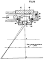
- Figure 19 shows in section an embodiment of this auxiliary source.
- It comprises a housing 62 in which is enclosed an annular fluorescent source 63 held in place by centering joints 64 and 65.
- a white screen diffusing 66 plane or spherical In the bottom of the housing 62 is removably mounted a white screen diffusing 66 plane or spherical.
- the screen 66 is integral with a plug 67 screwed into the housing 62, which makes it possible to adjust the distance between the screen 66 and the annular fluorescent source 63, the screen 66 being arranged in the axis of this source.
- a lens constituted by a meniscus 69 In the housing, opposite the screen 66, disposed, in a barrel 68 screwed into the housing 62, a lens constituted by a meniscus 69.
- a tubular screen 70 adjustable along the axis of the optical system so as to modify the distribution of the illuminations on the diffusing plane.
- a reflecting truncated cone 71 intended to suppress the cat's eye effect at the exit pupil of the meniscus 69.
- the tubular screen 70 ( Figure 19) which changes the light distribution in the plane of the diffusing screen 66, can be replaced by a field lens 72 and a corrective screen 73 COS 4 a.
- the focal point of the field lens 72 is combined with the image of the front pupil (small base of the truncated cone 71) of the meniscus 69.
- the corrective screen 73 is placed in a parallel beam against the field lens 72 between it ci and the broadcasting screen.
- the diffusing screen 66 is conveniently located relative to the annular source 63 so that its illumination is uniform.
- the front pupil of the objective can be completed by an adjustable diaphragm 74 and by a disc 75 carrying colored glasses 76-77.
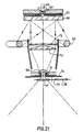
- the white diffusing screen 66 can be replaced by a transparent, translucent or opaline disc 90 (FIG. 21) made of synthetic glass, such as a poly (methyl methacrylate), for example that put on the market under the name "Altuglas by the company Altulor (France).
- a white opaque screen 91 carrying the reproduction of a radial gradient intended to modify the distribution of the luminance of the disc 90.
- This screen 91 is obtained by photography or by any other suitable process.
- a photoelectric cell 93 placed behind an opening 92 formed in the center of this degraded screen. This cell is used to control and control the intensity of the light tube 63.
- all the other elements of the auxiliary source assembly of FIG. 21 are identical to those of FIG. 20. This latter device can be provided in the mode Fig. 19.
- the apparatus which is the subject of the present invention makes it possible to obtain a certain number of advantages from the practical point of view. It allows in particular to reduce the exposure times up to 10 times compared to the devices of the prior art. It also makes it possible to obtain very good reproductions with sources 4 to 5 times less powerful than those of the known art, for example with sources of 5 KW. It should be added, as already mentioned above, that it is possible, thanks to the device according to the invention, to increase the maximum usable formats to reach for example a format of 20 x 25 cm for the original. and 50 x 65 cm for reproduction.
- the apparatus according to the invention finds an application in the industrial field: to carry out a reproduction, only the main source is obligatory (FIG. 7), but, to make photo-engraving, it is essential to provide in addition a source auxiliary ( Figures 18 to 21).
Landscapes
- Physics & Mathematics (AREA)
- General Physics & Mathematics (AREA)
- Lenses (AREA)
- Light Sources And Details Of Projection-Printing Devices (AREA)
- Projection Apparatus (AREA)
Applications Claiming Priority (2)
| Application Number | Priority Date | Filing Date | Title |
|---|---|---|---|
| FR7716947 | 1977-06-03 | ||
| FR7716947A FR2393338A1 (fr) | 1977-06-03 | 1977-06-03 | Perfectionnements aux appareils de reproduction photographique de documents transparents |
Publications (2)
| Publication Number | Publication Date |
|---|---|
| EP0000450A1 EP0000450A1 (fr) | 1979-01-24 |
| EP0000450B1 true EP0000450B1 (fr) | 1981-03-25 |
Family
ID=9191622
Family Applications (1)
| Application Number | Title | Priority Date | Filing Date |
|---|---|---|---|
| EP78400010A Expired EP0000450B1 (fr) | 1977-06-03 | 1978-06-01 | Appareils de reproduction photographique de documents transparents, notamment du type agrandisseur photographique |
Country Status (6)
| Country | Link |
|---|---|
| US (1) | US4229097A (it) |
| EP (1) | EP0000450B1 (it) |
| JP (1) | JPS5417724A (it) |
| DE (1) | DE2860556D1 (it) |
| FR (1) | FR2393338A1 (it) |
| IT (1) | IT1095283B (it) |
Families Citing this family (11)
| Publication number | Priority date | Publication date | Assignee | Title |
|---|---|---|---|---|
| US4298275A (en) * | 1980-01-07 | 1981-11-03 | Xerox Corporation | Radially varying transmission filter for wide angle copying device |
| EP0033185B1 (en) * | 1980-01-07 | 1984-05-23 | Xerox Corporation | Method and apparatus for compensating for illumination defects in an optical system |
| US4298274A (en) * | 1980-01-07 | 1981-11-03 | Rees James D | Variable density filter for a multi-magnification copying device |
| US4445774A (en) * | 1982-04-30 | 1984-05-01 | Xerox Corporation | Document imaging system with improved exposure uniformity at image plane |
| US5014086A (en) * | 1989-03-31 | 1991-05-07 | E. I. Du Pont De Nemours And Company | Adjustable dot gain simulation for color proofing |
| DE59209275D1 (de) * | 1992-09-09 | 1998-05-14 | Gretag Imaging Ag | Beleuchtungssystem für fotografische Kopiergeräte |
| US5461456A (en) * | 1992-11-24 | 1995-10-24 | General Signal Corporation | Spatial uniformity varier for microlithographic illuminator |
| DE10046353A1 (de) * | 2000-09-19 | 2002-04-11 | Agfa Gevaert Ag | Beleuchtungseinrichtung zum Beleuchten einer transparenten Bildvorlage |
| DE102004059951A1 (de) * | 2004-08-17 | 2006-02-23 | Giesecke & Devrient Gmbh | Vorrichtung zur Untersuchung von Dokumenten |
| EP2042521A1 (en) | 2006-03-29 | 2009-04-01 | Nippon Shokubai Co., Ltd. | Method of producing polyacrylic acid (salt) water-absorbent resin |
| DE102023106742B3 (de) | 2023-03-17 | 2024-07-18 | Leica Microsystems Cms Gmbh | Kondensorsystem und Mikroskopsystem |
Family Cites Families (5)
| Publication number | Priority date | Publication date | Assignee | Title |
|---|---|---|---|---|
| FR1021016A (fr) * | 1950-06-27 | 1953-02-13 | Agrandisseur à correction de contraste | |
| DE1225041B (de) * | 1964-07-16 | 1966-09-15 | Multiblitz Geraete Dr Ing D A | Vorrichtung zur photographischen Belichtung, vorzugsweise fuer Vergroesserungsgeraete |
| US3834813A (en) * | 1970-10-15 | 1974-09-10 | Haggar Co | Diazo printing system |
| US3922085A (en) * | 1974-08-22 | 1975-11-25 | Tamarack Scient Co Inc | Illuminator for microphotography |
| CH597618A5 (it) * | 1975-12-02 | 1978-04-14 | Zelacolor Syst |
-
1977
- 1977-06-03 FR FR7716947A patent/FR2393338A1/fr active Granted
-
1978
- 1978-05-31 IT IT24086/78A patent/IT1095283B/it active
- 1978-05-31 US US05/911,073 patent/US4229097A/en not_active Expired - Lifetime
- 1978-06-01 EP EP78400010A patent/EP0000450B1/fr not_active Expired
- 1978-06-01 DE DE7878400010T patent/DE2860556D1/de not_active Expired
- 1978-06-02 JP JP6584878A patent/JPS5417724A/ja active Pending
Also Published As
| Publication number | Publication date |
|---|---|
| IT1095283B (it) | 1985-08-10 |
| FR2393338B1 (it) | 1980-05-23 |
| IT7824086A0 (it) | 1978-05-31 |
| EP0000450A1 (fr) | 1979-01-24 |
| JPS5417724A (en) | 1979-02-09 |
| FR2393338A1 (fr) | 1978-12-29 |
| US4229097A (en) | 1980-10-21 |
| DE2860556D1 (en) | 1981-04-16 |
Similar Documents
| Publication | Publication Date | Title |
|---|---|---|
| CA1260297A (fr) | Dispositif d'eclairage notamment projecteur scenique simultanement reglable selon tous ses parametres | |
| US7929220B2 (en) | Adjustable apodized lens aperture | |
| EP0000450B1 (fr) | Appareils de reproduction photographique de documents transparents, notamment du type agrandisseur photographique | |
| FR2805351A1 (fr) | Systeme optique d'eclairage et dispositif d'affichage du type a projection utilisant le systeme | |
| WO2022128061A1 (fr) | Boite a illumination homogene pour imagerie photographique ou par camera | |
| FR2487993A1 (fr) | Ensemble d'eclairement artificiel pour appareil photographique et reflecteur pour cet ensemble | |
| EP2860582B1 (fr) | Installation pour l'acquisition de portraits photographiques | |
| EP0001951B1 (fr) | Dispositif de projection permettant la prise de vue de l'image projetée d'un objet | |
| EP1477019B1 (fr) | Procede pour transferer une image numerique en vue de sa restitution visuelle, et dispositif pour la mise en oeuvre de ce procede | |
| FR2667954A1 (fr) | Dispositif compact de coloration de faisceau lumineux et objectif correspondant. | |
| JPS6343128A (ja) | 写真光学台 | |
| EP0058186B1 (fr) | Agrandisseur photographique a source lumineuse ponctuelle | |
| FR2693561A1 (fr) | Source de lumière polarisée et rétroprojecteur utilisant cette source. | |
| WO2024133102A1 (fr) | Dispositif de filtrage à effet variable | |
| BE444835A (it) | ||
| FR2472207A1 (fr) | Procede pour la reproduction d'images a partir d'un support d'images transparent sur un support photosensible et dispositif pour la mise en oeuvre de ce procede | |
| FR2760856A1 (fr) | Dispositif d'eclairement | |
| BE489206A (it) | ||
| FR2580823A1 (fr) | Dispositif pour la projection de decors notamment pour la realisation de photographies | |
| CH279948A (fr) | Projecteur cinématographique. | |
| BE428761A (it) | ||
| BE486383A (it) | ||
| EP3646107A1 (fr) | Dispositif d'illumination diffractif a angle de diffraction augmente | |
| BE520500A (it) | ||
| BE377406A (it) |
Legal Events
| Date | Code | Title | Description |
|---|---|---|---|
| PUAI | Public reference made under article 153(3) epc to a published international application that has entered the european phase |
Free format text: ORIGINAL CODE: 0009012 |
|
| AK | Designated contracting states |
Designated state(s): BE CH DE FR GB LU NL SE |
|
| 17P | Request for examination filed | ||
| DET | De: translation of patent claims | ||
| GRAA | (expected) grant |
Free format text: ORIGINAL CODE: 0009210 |
|
| AK | Designated contracting states |
Designated state(s): BE CH DE FR GB LU NL SE |
|
| REF | Corresponds to: |
Ref document number: 2860556 Country of ref document: DE Date of ref document: 19810416 |
|
| PG25 | Lapsed in a contracting state [announced via postgrant information from national office to epo] |
Ref country code: LU Free format text: LAPSE BECAUSE OF NON-PAYMENT OF DUE FEES Effective date: 19810630 |
|
| PGFP | Annual fee paid to national office [announced via postgrant information from national office to epo] |
Ref country code: FR Payment date: 19830628 Year of fee payment: 6 |
|
| PGFP | Annual fee paid to national office [announced via postgrant information from national office to epo] |
Ref country code: LU Payment date: 19831019 Year of fee payment: 6 |
|
| PGFP | Annual fee paid to national office [announced via postgrant information from national office to epo] |
Ref country code: NL Payment date: 19831024 Year of fee payment: 6 |
|
| PGFP | Annual fee paid to national office [announced via postgrant information from national office to epo] |
Ref country code: DE Payment date: 19831026 Year of fee payment: 6 |
|
| PGFP | Annual fee paid to national office [announced via postgrant information from national office to epo] |
Ref country code: SE Payment date: 19831031 Year of fee payment: 6 Ref country code: CH Payment date: 19831031 Year of fee payment: 6 |
|
| PGFP | Annual fee paid to national office [announced via postgrant information from national office to epo] |
Ref country code: BE Payment date: 19831130 Year of fee payment: 6 |
|
| PG25 | Lapsed in a contracting state [announced via postgrant information from national office to epo] |
Ref country code: SE Effective date: 19840602 |
|
| PG25 | Lapsed in a contracting state [announced via postgrant information from national office to epo] |
Ref country code: CH Effective date: 19840630 Ref country code: BE Effective date: 19840630 |
|
| BERE | Be: lapsed |
Owner name: ANVAR AGENCE NATIONALE DE VALORISATION DE LA RECH Effective date: 19840601 |
|
| PG25 | Lapsed in a contracting state [announced via postgrant information from national office to epo] |
Ref country code: NL Effective date: 19850101 |
|
| GBPC | Gb: european patent ceased through non-payment of renewal fee | ||
| NLV4 | Nl: lapsed or anulled due to non-payment of the annual fee | ||
| PG25 | Lapsed in a contracting state [announced via postgrant information from national office to epo] |
Ref country code: FR Free format text: LAPSE BECAUSE OF NON-PAYMENT OF DUE FEES Effective date: 19850228 |
|
| REG | Reference to a national code |
Ref country code: CH Ref legal event code: PL |
|
| PG25 | Lapsed in a contracting state [announced via postgrant information from national office to epo] |
Ref country code: DE Effective date: 19850301 |
|
| REG | Reference to a national code |
Ref country code: FR Ref legal event code: ST |
|
| PG25 | Lapsed in a contracting state [announced via postgrant information from national office to epo] |
Ref country code: GB Free format text: LAPSE BECAUSE OF NON-PAYMENT OF DUE FEES Effective date: 19881117 |
|
| EUG | Se: european patent has lapsed |
Ref document number: 78400010.1 Effective date: 19850612 |
|
| PLBE | No opposition filed within time limit |
Free format text: ORIGINAL CODE: 0009261 |
|
| STAA | Information on the status of an ep patent application or granted ep patent |
Free format text: STATUS: NO OPPOSITION FILED WITHIN TIME LIMIT |