EP0000713B1 - Dispositif pour l'alimentation et la distribution de petites pièces et/ou pour l'épandage de matières granuleuses - Google Patents
Dispositif pour l'alimentation et la distribution de petites pièces et/ou pour l'épandage de matières granuleuses Download PDFInfo
- Publication number
- EP0000713B1 EP0000713B1 EP78100441A EP78100441A EP0000713B1 EP 0000713 B1 EP0000713 B1 EP 0000713B1 EP 78100441 A EP78100441 A EP 78100441A EP 78100441 A EP78100441 A EP 78100441A EP 0000713 B1 EP0000713 B1 EP 0000713B1
- Authority
- EP
- European Patent Office
- Prior art keywords
- container
- outlet
- spreading
- opening
- spade
- Prior art date
- Legal status (The legal status is an assumption and is not a legal conclusion. Google has not performed a legal analysis and makes no representation as to the accuracy of the status listed.)
- Expired
Links
- 239000000463 material Substances 0.000 title claims description 14
- 230000002093 peripheral effect Effects 0.000 claims description 6
- 150000003839 salts Chemical class 0.000 claims description 5
- 239000008187 granular material Substances 0.000 claims description 4
- 239000004576 sand Substances 0.000 claims description 4
- 238000009432 framing Methods 0.000 claims 2
- 239000003337 fertilizer Substances 0.000 description 9
- NJPPVKZQTLUDBO-UHFFFAOYSA-N novaluron Chemical class C1=C(Cl)C(OC(F)(F)C(OC(F)(F)F)F)=CC=C1NC(=O)NC(=O)C1=C(F)C=CC=C1F NJPPVKZQTLUDBO-UHFFFAOYSA-N 0.000 description 5
- 238000004806 packaging method and process Methods 0.000 description 4
- 210000000078 claw Anatomy 0.000 description 3
- 230000000694 effects Effects 0.000 description 3
- 241000196324 Embryophyta Species 0.000 description 2
- 230000002349 favourable effect Effects 0.000 description 2
- 239000004033 plastic Substances 0.000 description 2
- 239000003795 chemical substances by application Substances 0.000 description 1
- 230000006835 compression Effects 0.000 description 1
- 238000007906 compression Methods 0.000 description 1
- 230000001419 dependent effect Effects 0.000 description 1
- -1 for example Substances 0.000 description 1
- 238000009434 installation Methods 0.000 description 1
- 239000002991 molded plastic Substances 0.000 description 1
- 230000000717 retained effect Effects 0.000 description 1
- 239000000126 substance Substances 0.000 description 1
Images


Classifications
-
- B—PERFORMING OPERATIONS; TRANSPORTING
- B65—CONVEYING; PACKING; STORING; HANDLING THIN OR FILAMENTARY MATERIAL
- B65D—CONTAINERS FOR STORAGE OR TRANSPORT OF ARTICLES OR MATERIALS, e.g. BAGS, BARRELS, BOTTLES, BOXES, CANS, CARTONS, CRATES, DRUMS, JARS, TANKS, HOPPERS, FORWARDING CONTAINERS; ACCESSORIES, CLOSURES, OR FITTINGS THEREFOR; PACKAGING ELEMENTS; PACKAGES
- B65D83/00—Containers or packages with special means for dispensing contents
- B65D83/06—Containers or packages with special means for dispensing contents for dispensing powdered or granular material
-
- A—HUMAN NECESSITIES
- A01—AGRICULTURE; FORESTRY; ANIMAL HUSBANDRY; HUNTING; TRAPPING; FISHING
- A01C—PLANTING; SOWING; FERTILISING
- A01C15/00—Fertiliser distributors
- A01C15/02—Fertiliser distributors for hand use
Definitions
- the invention relates to a device for storing and dispensing small parts and / or for scattering granular material, in particular salt, sand, fertilizer, seeds or the like, consisting of a container holding the material with a bottom designed as a slide and at least one on the slide subsequent outlet and / or scattering opening, which is assigned to a specific peripheral region of the container and is gripped by a blade which is directed radially outward at its free end.
- a device of this type which has become known from FR-A-2019 103 serves as a disposable packaging container for litter-shaped substances such as, for example, fertilizers, weed killers and the like.
- litter-shaped substances such as, for example, fertilizers, weed killers and the like.
- a wall of the packaging container namely close to the lower edge of the container, there are outlet openings distributed over its width.
- Below these outlet openings there is an inclined, flat, blade-shaped distribution device. The inclination of the blade is chosen in this way. that the spreading material flows out of the container via the shovel after the outlet openings have been released, without the need for a spreading movement.
- the width of the scatter is determined exclusively by the appropriate design of the blade, which can be exchangeable.
- This packaging container apart from the fact that it is not intended for repeated use, is disadvantageous for various reasons. Only a small spreading width can be achieved with the shovel-like distribution device. In addition, the discharge quantity cannot be varied. Finally, the outflow of the spreading agent cannot be interrupted, unless the container is tilted in such a way that the scoop-shaped distribution device is in a horizontal or approximately horizontal position. In any case, the known packaging container is not suitable for the large-scale distribution of road salt on sidewalks, for example.
- US-A-2 014 003 discloses a fertilizing tool for individual plants provided with a handle.
- This fertilizer tool is designed as a conically tapering container, the lower end of which has such a deformation that an annular segment-like outlet opening is formed.
- This exit opening is normally kept closed by a spring-loaded flap. The opening can only be released by placing the flap on the floor and then tilting the container relative to it against the spring force.
- the invention has for its object to eliminate the shortcomings peculiar to the devices described above and to create a device of the generic type which, with a simple structure, enables a relatively large and nevertheless targeted distribution of relatively large quantities of goods.
- this object is essentially achieved in that the metering scoop runs horizontally or is inclined slightly downwards relative to the horizontal, that the container is provided with a filling opening and that a bow handle is attached to the upper end of the container, which makes it turn allowed of the container about its vertical axis.
- a device designed in this way has the advantage that it can be used repeatedly and that the material cannot flow freely from the container, but rather is only dispensed when the material lying on the metering scoop in front of the outlet and / or scattering opening is removed.
- distributing grit such as salt, fertilizer and sand
- This is done by rotating the container around its vertical axis. The centrifugal force generated thereby throws the spreading material away from the metering scoop, so that further spreading material can emerge from the outlet and / or spreading opening.
- the slide extends from the outlet opening and / or the scattering opening with a constant inclination over the entire cross-section of the container. It has proven to be advantageous if the lower end of the chute delimits an approximately segment or lens-shaped outlet and / or scattering opening below the free end of the metering scoop with the adjacent peripheral region of the container.
- the metering scoop according to the invention is adjustable in height and / or inclination relative to the outlet and / or spreading opening.
- the metering scoop can be held by spring force at an adjustable distance from the outlet and / or scatter opening and against the force of the spring as a closure member against the outlet and / or scatter opening.
- the adjusting means for The opening width of the outlet and / or litter opening are accessible at all times and to enable easy and sensitive actuation, even when the container for storing and dispensing small parts is set up at assembly sites, it is provided that the outlet and / or scatter opening in a side wall at the lower end of the cross-sectionally polygonal container and can be closed by a slide movable parallel to this side wall or its size can be changed continuously.
- outlet and / or scatter opening is narrower than the side wall of the container which has it and the slide inclined towards the outlet and / or scatter opening within the entire housing cross-section following the outlet and / or spreading opening carries laterally and upwardly directed gusset-like guide surfaces which reach with their lower end as far as the metering scoop.
- the slide can run in a guide delimited by a frame seated on the outside of the housing and can be moved via an actuator consisting of a threaded spindle and a knurled nut or the like.
- the free end of the metering scoop adjoining the slide is formed by the lower leg of the frame.
- the device for storing and delivering small parts is set up on assembly sites, it is essential to assign a plate-like base to the container, which on the one hand, with cams and / or webs on its top, engages in a frame-side frame edge of the container on the foot side and on the other hand has an extension adjoining the metering scoop of the container.
- the extension of the base can be designed as a trough delimited by side walls and offset against the metering scoop, which allows the small parts emerging from the container to be removed within easy reach.
- the base in its rear part area is adapted to the outline shape of the frame edge of the container, while its extension tapers like a trapezoid. This makes it possible either to set up several devices in a row directly next to each other or to set them up along a curve alongside one another.
- 1 and 2 consists of an approximately drum-shaped or pot-shaped container 1, which is provided at its upper end with a preferably foldable bow handle 2 and whose filling opening can be closed by a lid 3.
- a metering scoop 8 with a fastening section 7 is suspended in the circumferential area of the container 1 opposite the outlet and / or scatter opening 6 reaches under.
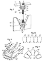
- FIG. 3 differs from that according to FIG. 1 essentially in that the free end portion of the metering scoop 8 projects to a certain extent beyond the outer circumference of the container 1 and thus enables a larger spreading width. So that the outlet and / or spreading opening 6 is nevertheless closed when the container 1 is placed on your floor, the container 1 is provided on its lower peripheral edge with a cutout 10, which the swung-up metering scoop 8 can reach through, as can be seen by the broken lines in FIG 3 is indicated.
- the metering scoop 8 is supported by a toggle or wing nut 1'1, which is adjustable on a threaded bolt 12 fastened to the slide 4.
- a toggle or wing nut 11 By actuating the toggle or wing nut 11, the downward movement of the metering scoop 8 and thus the passage height for the spreading material between the free end portion of the metering scoop 8 and the outlet and / or spreading opening 6 can be set differently.
- a compression spring 13 surrounding the threaded bolt 12 can be provided so that it forcibly presses the metering scoop 8 into the open position as soon as the container 1 is lifted off the floor.
- the bow handle 2 is mounted on the container 1 in such a way that it has the same radial position as the metering scoop 8. In this way, pick up the container 1 with the natural grip of the hand and turn it to a limited extent to achieve the scattering effect around its longitudinal axis.
- the device shown in FIGS. 4 to 6 for storing and dispensing small parts and / or for scattering granular material has a container 101 with a polygonal cross section, which is equipped near the upper end with a foldable bow handle 102 and its filling opening can be closed by a hinged lid 103 which is connected to the container 101 via hinges 104.
- a claw-like locking device 105 between the hinged lid 103 and the edge of the filling opening of the container 101 serves to secure the hinged lid in its closed position.
- the hinged lid 103 lies in a frame edge 101 ′′ which delimits the filling opening of the container 101 and which has a portion of its height which is inclined downwards towards the inside of the container.
- the bottom of the container 101 is formed by an inclined chute 107 which extends over the entire cross section of the housing and extends inclined towards the outlet and / or scatter opening 106.
- the metering scoop 109 and the lower boundary edge of the container 101 are jointly stabilized by a frame-like edge 101 ".
- the outlet and / or scatter opening 106 is assigned a slide 110 which can be moved parallel to the container wall 101 'and by means of which the outlet and / or scatter opening 106 can be closed and its size can be changed continuously as required.
- This slider 110 is 'performed molded frame 1 1 1 in the vertical direction and slidably through from the inside of the frame 111 projecting strips 112 with the container wall 101' in the outside of the container wall 101 retained in Kontakberlongung.
- the upper end of the threaded spindle 114 passes through two bearing eyes 120 with a threaded section 114 ′ of smaller diameter and 121, which are formed on the container wall 101 'and between which the knurled nut 115 rotatably supports.
- the threaded spindle 114 is displaced in the axial direction and therefore the slide 110 held in connection with it by jamming is moved accordingly.
- the adjustment of the slide 110 via the actuator 113 can be carried out easily and safely while the spreading device is on one Support surface, for example on the floor, rests.
- the container 101, the hinged lid 103, the slide 110 and the parts forming the actuator 113, namely the threaded spindle 114, the knurled nut 115 and the lock nut 119 consist of molded plastic parts.
- the bow handle 102 articulated on the container 101 can have a metallic bow, for example formed from wire, and a handle part 123 likewise made of plastic.
- Ribs 126 are arranged in a radial manner on the metering scoop 109.
- FIG. 9 shows a plate-like base 127, which can also be manufactured as a molded part made of plastic.
- This pedestal is equipped on the one hand on its top with cams 128 and on the other hand with webs 129, with which the container 101 can be brought into engagement via its frame-side frame edge 101 ".
- the base 127 is adapted in its rear portion to the outline of the frame edge 101 ′′ formed on the container 101 and, on the other hand, has a forward-looking extension 130 which tapers in a trapezoidal shape. When the container 101 is placed on the base 127, it closes Extension 130 of the base 127 to the metering scoop 109 of the container 101. It is advantageous if the extension 130 of the base 127 contains a recess 130 ′′ set against the metering scoop 109, which is delimited by side walls 130 ′ which are located laterally next to the Place the metering scoop 109 with angled sections against the side wall 101 of the container 101.
- a plurality of pedestals 127 can be placed in a row closely next to one another on a support surface, for example a table top, and in this way connected to it in a positionally secure manner by means of screws which, for example, penetrate holes 133 (FIG. 9) in the pedestals 127.
- pedestals 127 can also sit directly next to one another along an arcuate line, as can be seen from FIG. 11. In this case, too, these pedestals 127 can be attached to a support surface, for example on a table top.
- cams 128 each have holes 134, while on the container 101 there are molded on the lower frame edge 101 "cams 135 which contain holes corresponding to the holes 134.
- the pedestals 127 are then connected to the container in the manner of shoes.
- each of the bases 127 has a plurality of latching slots 131 ′ and 131 ′′ on its one longitudinal edge and a corresponding one on its other longitudinal edge Number of locking hooks 132 'and 132 ".
- 10 and 11 are particularly suitable if devices for storing and dispensing small parts have to be created at assembly sites in industry, which on the one hand should have an ergonomically favorable position relative to one another, but on the other hand easier handling when filling with small parts should be portable.
- the base 127 can of course also be attached to the container when it is used as a scattering device for granular material, in particular salt, sand, fertilizer, seeds or the like. This is particularly expedient if an enlargement of the spreading sector is desired when handling the spreading device. Due to the enlargement of the metering scoop, when the container 101 is rotated about its longitudinal axis, there is an increased centrifugal force effect, which results in a corresponding enlargement of the spreading sector.
Landscapes
- Life Sciences & Earth Sciences (AREA)
- Soil Sciences (AREA)
- Environmental Sciences (AREA)
- Engineering & Computer Science (AREA)
- Mechanical Engineering (AREA)
- Basic Packing Technique (AREA)
- Fertilizing (AREA)
- Adjustment And Processing Of Grains (AREA)
- Drying Of Solid Materials (AREA)
Claims (12)
Applications Claiming Priority (4)
| Application Number | Priority Date | Filing Date | Title |
|---|---|---|---|
| DE2733436 | 1977-07-25 | ||
| DE19772733436 DE2733436A1 (de) | 1977-07-25 | 1977-07-25 | Streuvorrichtung fuer koerniges gut |
| DE19787820059 DE7820059U1 (de) | 1978-07-04 | 1978-07-04 | Vorrichtung zur Bevorratung und Abgabe von Kleinteilen und/oder zum Streuen von koernigem Gut |
| DE7820059U | 1978-07-04 |
Publications (2)
| Publication Number | Publication Date |
|---|---|
| EP0000713A1 EP0000713A1 (fr) | 1979-02-21 |
| EP0000713B1 true EP0000713B1 (fr) | 1982-01-27 |
Family
ID=25772387
Family Applications (1)
| Application Number | Title | Priority Date | Filing Date |
|---|---|---|---|
| EP78100441A Expired EP0000713B1 (fr) | 1977-07-25 | 1978-07-19 | Dispositif pour l'alimentation et la distribution de petites pièces et/ou pour l'épandage de matières granuleuses |
Country Status (4)
| Country | Link |
|---|---|
| EP (1) | EP0000713B1 (fr) |
| DE (1) | DE2861572D1 (fr) |
| IT (1) | IT1112281B (fr) |
| NO (1) | NO782462L (fr) |
Families Citing this family (2)
| Publication number | Priority date | Publication date | Assignee | Title |
|---|---|---|---|---|
| DE102007045027B4 (de) * | 2007-09-20 | 2009-10-01 | Behr, Ron, Dipl.-Wirtsch. Ing. | Behälter zur Aufnahme von Schüttgut wie körniges Gut, Sand, Salz, Samen, Splitt, Dünger oder Mischformen |
| CN105900571A (zh) * | 2016-06-23 | 2016-08-31 | 陈卫国 | 多功能播种器 |
Family Cites Families (6)
| Publication number | Priority date | Publication date | Assignee | Title |
|---|---|---|---|---|
| US1632540A (en) * | 1926-07-15 | 1927-06-14 | Henry R Clarke | Fertilizer distributor |
| US2014003A (en) * | 1933-12-15 | 1935-09-10 | Mary E Mcrae | Fertilizing implement |
| FR830631A (fr) * | 1937-12-10 | 1938-08-04 | Venot & Cie | Dispositif de manutention pour matières en silos |
| CH335712A (de) * | 1956-10-25 | 1959-01-31 | Kocher Walter | Sand- und Kies-Streueinrichtung an Transportwagen |
| GB1112343A (en) * | 1965-06-11 | 1968-05-01 | Fisons Ltd | Hoppers |
| FR2019103A1 (fr) * | 1968-09-28 | 1970-06-26 | Norddeutsche Affinerie |
-
1978
- 1978-07-17 IT IT25770/78A patent/IT1112281B/it active
- 1978-07-17 NO NO782462A patent/NO782462L/no unknown
- 1978-07-19 EP EP78100441A patent/EP0000713B1/fr not_active Expired
- 1978-07-19 DE DE7878100441T patent/DE2861572D1/de not_active Expired
Also Published As
| Publication number | Publication date |
|---|---|
| EP0000713A1 (fr) | 1979-02-21 |
| IT1112281B (it) | 1986-01-13 |
| IT7825770A0 (it) | 1978-07-17 |
| DE2861572D1 (en) | 1982-03-11 |
| NO782462L (no) | 1979-01-26 |
Similar Documents
| Publication | Publication Date | Title |
|---|---|---|
| DE3308058A1 (de) | Streuvorrichtung | |
| DE2306641A1 (de) | Materialstreuvorrichtung mit aufsteckbarem materialbehaelter | |
| DE3529452A1 (de) | Streugeraet | |
| DE2943721A1 (de) | Streugeraet fuer koerniges oder pulveriges streugut | |
| DE69818402T2 (de) | Körnerstreuer und -behälter | |
| DE69524680T2 (de) | Gerät zum Streuen von körnigem und/oder staubigem Material | |
| DE19813980B4 (de) | Einachsiger Streuwagen | |
| DE3532756C1 (en) | Broadcaster, especially for granular fertilizers | |
| DE1782716A1 (de) | Streugeraet | |
| EP0000713B1 (fr) | Dispositif pour l'alimentation et la distribution de petites pièces et/ou pour l'épandage de matières granuleuses | |
| DE2205510A1 (de) | Vorrichtung zum Ausstreuen von körnigem oder pulverigem Material | |
| DE69708561T2 (de) | Streuer für körniges und/oder pulveriges Gut | |
| DE1457836A1 (de) | Streugeraet fuer koerniges oder pulverfoermiges Gut | |
| DE2044566A1 (de) | Vorrichtung zum Ausstreuen von Material | |
| DE1457863B2 (de) | Streugerat | |
| DE102005015228B4 (de) | Schleuderstreuer für Streugut | |
| DE2010863C3 (de) | Streugerät | |
| DE20219789U1 (de) | Streubox zum Tragen für kleinkörniges Streugut | |
| DE1945076B2 (de) | Streugerät für körniges oder pulveriges Streugut | |
| DE3405245A1 (de) | Streugeraet fuer koerniges und/oder pulveriges streugut | |
| DE2912306C2 (de) | Streuer für insbesondere Stalldung | |
| DE4104685C1 (fr) | ||
| DE831468C (de) | Vorrichtung zum Ausbringen von Streugut aus Vorratsbehaeltern | |
| DE1945077B2 (de) | Streugerät für körniges oder pulveriges Streugut | |
| DE2733436A1 (de) | Streuvorrichtung fuer koerniges gut |
Legal Events
| Date | Code | Title | Description |
|---|---|---|---|
| PUAI | Public reference made under article 153(3) epc to a published international application that has entered the european phase |
Free format text: ORIGINAL CODE: 0009012 |
|
| AK | Designated contracting states |
Designated state(s): BE DE FR GB LU NL SE CH |
|
| 17P | Request for examination filed | ||
| GRAA | (expected) grant |
Free format text: ORIGINAL CODE: 0009210 |
|
| AK | Designated contracting states |
Designated state(s): BE CH DE FR GB LU NL SE |
|
| PG25 | Lapsed in a contracting state [announced via postgrant information from national office to epo] |
Ref country code: BE Effective date: 19820127 Ref country code: SE Effective date: 19820127 Ref country code: NL Effective date: 19820127 Ref country code: FR Free format text: THE PATENT HAS BEEN ANNULLED BY A DECISION OF A NATIONAL AUTHORITY Effective date: 19820127 |
|
| REF | Corresponds to: |
Ref document number: 2861572 Country of ref document: DE Date of ref document: 19820311 |
|
| NLV1 | Nl: lapsed or annulled due to failure to fulfill the requirements of art. 29p and 29m of the patents act | ||
| PG25 | Lapsed in a contracting state [announced via postgrant information from national office to epo] |
Ref country code: LU Free format text: LAPSE BECAUSE OF NON-PAYMENT OF DUE FEES Effective date: 19820731 Ref country code: CH Effective date: 19820731 |
|
| REG | Reference to a national code |
Ref country code: CH Ref legal event code: PL |
|
| GBPC | Gb: european patent ceased through non-payment of renewal fee | ||
| PG25 | Lapsed in a contracting state [announced via postgrant information from national office to epo] |
Ref country code: DE Effective date: 19840403 |
|
| PG25 | Lapsed in a contracting state [announced via postgrant information from national office to epo] |
Ref country code: GB Effective date: 19881117 |
|
| PLBE | No opposition filed within time limit |
Free format text: ORIGINAL CODE: 0009261 |
|
| STAA | Information on the status of an ep patent application or granted ep patent |
Free format text: STATUS: NO OPPOSITION FILED WITHIN TIME LIMIT |