EP0000995A1 - Apparat und Verfahren zur kontrollierten Behandlung von strahlungsempfindlichen Vorrichtungen in Abhängigkeit von der Entwicklertemperatur - Google Patents
Apparat und Verfahren zur kontrollierten Behandlung von strahlungsempfindlichen Vorrichtungen in Abhängigkeit von der Entwicklertemperatur Download PDFInfo
- Publication number
- EP0000995A1 EP0000995A1 EP78300279A EP78300279A EP0000995A1 EP 0000995 A1 EP0000995 A1 EP 0000995A1 EP 78300279 A EP78300279 A EP 78300279A EP 78300279 A EP78300279 A EP 78300279A EP 0000995 A1 EP0000995 A1 EP 0000995A1
- Authority
- EP
- European Patent Office
- Prior art keywords
- developer liquid
- temperature
- developer
- plate
- dependent
- Prior art date
- Legal status (The legal status is an assumption and is not a legal conclusion. Google has not performed a legal analysis and makes no representation as to the accuracy of the status listed.)
- Granted
Links
- 239000007788 liquid Substances 0.000 title claims abstract description 86
- 230000005855 radiation Effects 0.000 title claims abstract description 74
- 238000012545 processing Methods 0.000 title claims abstract description 28
- 238000000034 method Methods 0.000 title claims description 9
- 230000001419 dependent effect Effects 0.000 claims abstract description 22
- 230000001105 regulatory effect Effects 0.000 claims description 6
- 230000001276 controlling effect Effects 0.000 claims description 4
- 230000008569 process Effects 0.000 claims description 3
- 230000036962 time dependent Effects 0.000 claims description 3
- 238000004519 manufacturing process Methods 0.000 abstract description 3
- 206010073306 Exposure to radiation Diseases 0.000 abstract 1
- 238000000576 coating method Methods 0.000 description 18
- 239000011248 coating agent Substances 0.000 description 17
- 239000000523 sample Substances 0.000 description 12
- -1 silver halide Chemical class 0.000 description 9
- 238000011161 development Methods 0.000 description 8
- 238000010586 diagram Methods 0.000 description 7
- 239000004115 Sodium Silicate Substances 0.000 description 6
- 229920001971 elastomer Polymers 0.000 description 6
- NTHWMYGWWRZVTN-UHFFFAOYSA-N sodium silicate Chemical compound [Na+].[Na+].[O-][Si]([O-])=O NTHWMYGWWRZVTN-UHFFFAOYSA-N 0.000 description 6
- 229910052911 sodium silicate Inorganic materials 0.000 description 6
- 239000007787 solid Substances 0.000 description 6
- 239000000758 substrate Substances 0.000 description 6
- 239000007864 aqueous solution Substances 0.000 description 5
- 230000008859 change Effects 0.000 description 5
- 235000019795 sodium metasilicate Nutrition 0.000 description 5
- 229910052753 mercury Inorganic materials 0.000 description 4
- 229920005989 resin Polymers 0.000 description 4
- 239000011347 resin Substances 0.000 description 4
- 239000007921 spray Substances 0.000 description 4
- 230000000694 effects Effects 0.000 description 3
- 229920003986 novolac Polymers 0.000 description 3
- 229910052709 silver Inorganic materials 0.000 description 3
- 239000004332 silver Substances 0.000 description 3
- AZQWKYJCGOJGHM-UHFFFAOYSA-N 1,4-benzoquinone Chemical compound O=C1C=CC(=O)C=C1 AZQWKYJCGOJGHM-UHFFFAOYSA-N 0.000 description 2
- WTQZSMDDRMKJRI-UHFFFAOYSA-N 4-diazoniophenolate Chemical compound [O-]C1=CC=C([N+]#N)C=C1 WTQZSMDDRMKJRI-UHFFFAOYSA-N 0.000 description 2
- 239000004411 aluminium Substances 0.000 description 2
- XAGFODPZIPBFFR-UHFFFAOYSA-N aluminium Chemical compound [Al] XAGFODPZIPBFFR-UHFFFAOYSA-N 0.000 description 2
- 229910052782 aluminium Inorganic materials 0.000 description 2
- 230000003247 decreasing effect Effects 0.000 description 2
- 238000009792 diffusion process Methods 0.000 description 2
- 238000007654 immersion Methods 0.000 description 2
- 230000007246 mechanism Effects 0.000 description 2
- 239000000203 mixture Substances 0.000 description 2
- 238000012546 transfer Methods 0.000 description 2
- BLPUXJIIRIWMSQ-QPJJXVBHSA-N 2-[(e)-3-phenylprop-2-enylidene]propanedioic acid Chemical compound OC(=O)C(C(O)=O)=C\C=C\C1=CC=CC=C1 BLPUXJIIRIWMSQ-QPJJXVBHSA-N 0.000 description 1
- UXVMQQNJUSDDNG-UHFFFAOYSA-L Calcium chloride Chemical compound [Cl-].[Cl-].[Ca+2] UXVMQQNJUSDDNG-UHFFFAOYSA-L 0.000 description 1
- LFQSCWFLJHTTHZ-UHFFFAOYSA-N Ethanol Chemical compound CCO LFQSCWFLJHTTHZ-UHFFFAOYSA-N 0.000 description 1
- 229920000084 Gum arabic Polymers 0.000 description 1
- 239000002202 Polyethylene glycol Substances 0.000 description 1
- 241000978776 Senegalia senegal Species 0.000 description 1
- HCHKCACWOHOZIP-UHFFFAOYSA-N Zinc Chemical compound [Zn] HCHKCACWOHOZIP-UHFFFAOYSA-N 0.000 description 1
- 239000000205 acacia gum Substances 0.000 description 1
- 235000010489 acacia gum Nutrition 0.000 description 1
- 230000009471 action Effects 0.000 description 1
- 238000013019 agitation Methods 0.000 description 1
- 230000004075 alteration Effects 0.000 description 1
- 239000001110 calcium chloride Substances 0.000 description 1
- 229910001628 calcium chloride Inorganic materials 0.000 description 1
- 238000001816 cooling Methods 0.000 description 1
- 230000007423 decrease Effects 0.000 description 1
- 125000000664 diazo group Chemical group [N-]=[N+]=[*] 0.000 description 1
- 238000007598 dipping method Methods 0.000 description 1
- 239000012153 distilled water Substances 0.000 description 1
- 150000002148 esters Chemical class 0.000 description 1
- 238000005530 etching Methods 0.000 description 1
- 238000002474 experimental method Methods 0.000 description 1
- VOZRXNHHFUQHIL-UHFFFAOYSA-N glycidyl methacrylate Chemical compound CC(=C)C(=O)OCC1CO1 VOZRXNHHFUQHIL-UHFFFAOYSA-N 0.000 description 1
- 238000001459 lithography Methods 0.000 description 1
- 239000000463 material Substances 0.000 description 1
- 230000003287 optical effect Effects 0.000 description 1
- 239000003960 organic solvent Substances 0.000 description 1
- 229920001223 polyethylene glycol Polymers 0.000 description 1
- 238000005201 scrubbing Methods 0.000 description 1
- 239000000243 solution Substances 0.000 description 1
- 239000002904 solvent Substances 0.000 description 1
- 239000000126 substance Substances 0.000 description 1
- 238000002834 transmittance Methods 0.000 description 1
- XLYOFNOQVPJJNP-UHFFFAOYSA-N water Chemical compound O XLYOFNOQVPJJNP-UHFFFAOYSA-N 0.000 description 1
- 229910052724 xenon Inorganic materials 0.000 description 1
- FHNFHKCVQCLJFQ-UHFFFAOYSA-N xenon atom Chemical compound [Xe] FHNFHKCVQCLJFQ-UHFFFAOYSA-N 0.000 description 1
- 229910052725 zinc Inorganic materials 0.000 description 1
- 239000011701 zinc Substances 0.000 description 1
Images

Classifications
-
- G—PHYSICS
- G03—PHOTOGRAPHY; CINEMATOGRAPHY; ANALOGOUS TECHNIQUES USING WAVES OTHER THAN OPTICAL WAVES; ELECTROGRAPHY; HOLOGRAPHY
- G03D—APPARATUS FOR PROCESSING EXPOSED PHOTOGRAPHIC MATERIALS; ACCESSORIES THEREFOR
- G03D13/00—Processing apparatus or accessories therefor, not covered by groups G11B3/00 - G11B11/00
- G03D13/006—Temperature control of the developer
-
- G—PHYSICS
- G03—PHOTOGRAPHY; CINEMATOGRAPHY; ANALOGOUS TECHNIQUES USING WAVES OTHER THAN OPTICAL WAVES; ELECTROGRAPHY; HOLOGRAPHY
- G03D—APPARATUS FOR PROCESSING EXPOSED PHOTOGRAPHIC MATERIALS; ACCESSORIES THEREFOR
- G03D13/00—Processing apparatus or accessories therefor, not covered by groups G11B3/00 - G11B11/00
- G03D13/007—Processing control, e.g. test strip, timing devices
Definitions
- Such radiation sensitive devices are used in the production of, for example, printing plates, in particular lithographic printing plates; printed circuits; and integrated circuits.
- Radiation sensitive devices for use in the production of lithographic printing plates usually consist of a substrate in the form of a metallic support sheet, which is mechanically and/or chemically treated to provide a suitable working surface and which carries the radiation sensitive coating.
- the device is image-wise exposed to actinic radiation using either a negative or a positive transparency of an appropriate subject. The effect of actinic radiation is to alter the solubility of the radiation-sensitive coating.
- the image-wise exposed device is then processed.
- an apparatus for processing an image-wise exposed radiation sensitive device which apparatus comprises
- the apparatus additionally includes a source of actinic radiation arranged in or adjacent to the apparatus so that the processing also involves the step of subjecting the device to an overall uniform exposure prior to or during its contact with developer liquid.
- a source of actinic radiation arranged in or adjacent to the apparatus so that the processing also involves the step of subjecting the device to an overall uniform exposure prior to or during its contact with developer liquid.
- the degree to which the device is subjected to radiation from said source may be controlled in dependence on said output signal. This may conveniently be effected by interposing a variable aperture between the source and the path and regulating the size of the aperture in dependence on said output signal.
- Positive working radiation-sensitive devices typified by quinone diazide sensitised devices are used in the technique known as 'screenless lithography' i.e. the technique in which the device is exposed directly through a continuous tone master, without the use of the conventional half tone screen. Processing the plate by subjecting it to an overall exposure before developing increases the range of tones that can be obtained. Again, however, it is difficult to obtain predictable and repeatable results when this is done manually.
- An apparatus of the invention including a source of actinic radiation as aforesaid can be used to process these plates, variations in the tonal range being produced by varying the duration of the intensity of the overall exposure. Alternatively if it is desired to keep these parameters constant, the tonal range can be varied by altering the speed at which the plates pass the radiation source. Clearly, variation of exposure duration and intensity and variation of plate speed can be combined to give better control of the tonal range.
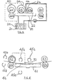
- the apparatus comprises a tank 1 for containing developer liquid, a pair of rubber covered input rollers 2 and 2a, a pair of rubber covered output rollers 3 and 3a and a d.c. electric motor 4 connected to drive the roller 2.
- Roller 2a is driven by contact with roller 2.
- the rollers 3, 3a may also be driven from the motor 4 if desired).
- a temperature sensitive member in the form of a probe 5 containing a thermistor is mounted in the tank 1 so as to lie in the developer.
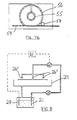
- the electrical control circuit consists of a constant voltage source 9 in the form of an integrated circuit voltage regulator, a temperature voltage converter 10 incorporating the thermistor, and a servodevice 11 in the form of a d.c. thyristor controller, the output of which controls the speed of the motor 4.
- the regulated voltage from the source 9 is fed through the thermistor 12 to a pair of d.c. amplifiers 13 and 14. Variation in the temperature of the thermistor 12 causes a change in its resistance which in turn produces a change in the input voltage to the amplifier 13.
- the output of the amplifier 14 is connected to the servo device 11.
- a variable resistor 15 is provided to vary the gain of the amplifier 13.
- the temperature compensation that will be suitable for one combination of radiation sensitive coating and developer liquid will not necessarily be suitable for another. Suitable variation of the change in motor speed with temperature may be obtained by adjusting the potentiometer 15. Further, in the case of a given radiation sensitive coating/developer liquid combination the potentiometer 15 may be adjusted to vary the contrast of the developed plate. Moreover, the setting of thepotentiometer 15 may be varied to allow for an alteration in the activity of the developer liquid as a result of partial exhaustion.
- the apparatus includes a pair of rubber covered input rollers 20 and 20a, a pair of rubber covered output rollers 30 and 30a, and a d.c. electric motor 40 for driving the rollers 20 and 20a.
- the apparatus includes a separate reservoir 21 for developer liquid and a pump 25 for delivering developer liquid to a spray bar 26 located between a pair of plush covered rollers 23 and 23a driven by a separate motor 24.
- a planar member 22 is located under the rollers 23 and 23a and bar 26 and a catch tray 27 is provided to return developer liquid to the reservoir 21.
- the apparatus includes a temperature sensitive probe 28 similar to that of the apparatus of Figure 1 and this is preferably located in the reservoir 21 as shown.
- the apparatus also includes an electrical control circuit of the type shown in Figures 2 and 3 and the output from the servo device of the circuit is fed to motor 40 and/or motor 24.
- an image-wise exposed radiation sensitive plate is fed face upwards along a path between the input rollers 20 and 20a, between the rollers 23 and 23a and the member 22, and then between the output rollers 30 and 30a.
- the exposed radiation sensitive coating of the plate is contacted by the rollers 23 and 23a and development is carried out by a combined scrubbing and solvent action.
- the arrangement is such that with increased developer liquid temperature, (i) motor 40 (and hence rollers 20 and 20a) rotate faster and hence the residence time of the plate in the apparatus is shorter and (ii) motor 24 (and hence rollers 23 and 23a) rotate slower and hence the developer liquid on the exposed coating is subjected to a less severe agitation.
- the degree to which the plate is processed is thus dependent on the temperature of the developer liquid and, as in the case of the apparatus of Figures 1 to 3, this relationship can be adjusted as desired.
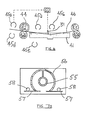
- the apparatus comprises a tank 41 forcontaining the developer liquid and a pair of rubber covered input rollers 42 and 42a and a pair of rubber covered output rollers 43 and 43a defining a path 46 through the apparatus.
- An electric motor 44 is included to drive the roller 42, roller 42a being frictionally driven by roller 42.
- the rollers 43 and 43a may also be driven from the motor 44 if desired.
- the apparatus also includes a means of subjecting radiation sensitive plates passing along the path 46 to an overall uniform exposure to actinic radiation. Preferably, this is in the form of a plurality of sources of actinic radiation and/or one or more moveable sources so that the apparatus can be used to process plates requiring to be subjected to an overall exposure from different positions.
- references 45a to 45e Examples of suitable positions are denoted by references 45a to 45e.
- the positions 45d and 45e are usable when the plate is being processed face down. In the case of position 45e the tank must, of course, be translucent.
- a means (not shown) is provided to sense the presence of a plate along said path 46 and to actuate the source of actinic radiation when the plate reaches a position along the path 46 at which it can receive radiation from the source. (Alternatively, the source may be actuated manually when the plate reaches a suitable position along the path).
- a temperature sensitive member in the form of a probe 31 containing a thermistor is mounted in the tank 41 so as to lie in the developer liquid.
- the thermistor forms part of a control circuit of the type described with reference to Figures 2 and 3 and is operably connected to the motor 44 so that the speed of the motor increases (and hence the residence time of the plate decreases) with increase in developer temperature.
- the thermistor may be operably connected to a means of regulating a variable aperture (e.g. in the form of a slit of adjustable width forming, for example, a part of a shutter mechanism) located between the radiation source and the plate path.
- an image-wise exposed radiation sensitive plate is fed into the input rollers 42 and 42a which move the same along the path 46 through the apparatus and then out of the apparatus via output rollers 43 and 43a.
- the plate is submerged in the developer liquid in the tank 41 whereby the more soluble areas of the image wise exposed radiation sensitive coating of the plate are selectively removed.
- the residence time of the plate is controlled in dependence on the developer liquid temperature. As the plate passes the source of actinic radiation the whole surface of the plate is exposed. In the case where the apparatus includes a variable aperture as above described, this too is regulated in dependence on the temperature of the developer liquid in order to give the plate a desired overall exposure dependent on said temperature.
- the source of actinic radiation may be of any suitable type, for example a mercury halide lamp, a pulsed xenon lamp or an ultra violet lamp.
- the apparatus may include one or more filters and a means of interposing the same between the plate path and the source as appropriate in dependence on said temperature so that the amount of radiation reaching the plate during the overall exposure is dependent on the temperature of the developer liquid.
- FIG. 6 parts corresponding to parts of the apparatus of Figure 5 are denoted by like reference numerals.
- the apparatus is identical to that of Figure 5 except that the probe 31 is not operably connected to motor 44.
- the probe 31 is operably connected to a means 50 of regulating the amount of radiation reaching the plate from the radiation source (45a) so that the degree to which the plate is given a uniform overall exposure as it passes through the apparatus is controlled in dependence on the developer liquid temperature.
- Means 50 is shown schematically in Figure 6. It may, for example, be in the form of a controllable aperture located between the source and the plate path. Such an arrangement is illustrated in Figure 7a.
- the source includes a tubular lamp 55 located within a casing 56 having a slit arranged transversely with respect to the path such that radiation from the source can impinge on plates passing along the plate path.
- Shutters 57 are mounted at the sides of the slit and co-operate with the slit to provide a variable aperture for the source.
- the shutters are displaceable towards one another so as to reduce the size of the aperture (and hence reduce the amount of radiation reaching the path) or away from one another so as to increase the size of the aperture (and hence increase the amount of radiation reaching the path).
- Each shutter 57 carries a rack which is engaged by a pinion 58 driven by a motor (not shown) so as to displace the shutters 57.
- the motor is operably connected to the probe immersed in the developer liquid in a manner such that the degree to which the pinion is rotated (andlence the size of the aperture)is dependent on the output signal generated by the probe and its associated circuitry. In this way, the amount of radiation to which the plates are subjected is determined by the developer liquid temperature.
- the means 50 may be in the form of a plurality of filters arranged to be selectively interposed between the source and the plate path.
- a displaceable radiation filter 59 which comprises adjacent portions of differing radiation transmittance.
- the filter 59 carries a rack which is engaged by the pinion 58. Rotation of the pinion causes the filter 59 to be displaced across the slit so that one or other of its portions is interposed between the source and the path. The amount of radiation reaching the path is dependent on which of these portions is interposed between the source and the path.
- the image-wise exposed radiation sensitive plate is placed on the member 22 face upwards.
- the plate may be placed in position manually or automatically).
- Developer liquid is sprayed onto the plate from a plurality of spray bars 26' arranged so that the entire surface of the stationary plate is contacted with developer liquid.
- the liquid line carrying developer liquid from the reservoir 21 to the spray bars 26' includes a valve 60 actuated by a timer 61 operably connected to the output signal generated by the probe 28 and its associated circuitry. The arrangement is such that the period of time during which developer liquid issues from the spray bars 26' is dependent on the developer liquid temperature.
- the apparatus of the present invention provides several advantages over conventional processors. It is possible to obtain repeatable plate processing accurately without having to monitor and adjust the working temperature of the developer, which thus can always be at the ambient temperature. Time is saved when the developer temperature is low e.g. at the start of processing in a cold environment, as it is not necessary to wait until the developer is heated to the normal working temperature as is the case with conventional developers. Further, in the case where the ambient temperature is higher than the normal working temperature, there is no need to provide a means of cooling the developer. This is particularly important in the case of large processors containing 30 or 40 litres of developer.
Landscapes
- Physics & Mathematics (AREA)
- General Physics & Mathematics (AREA)
- Photographic Processing Devices Using Wet Methods (AREA)
- Silver Salt Photography Or Processing Solution Therefor (AREA)
- Photosensitive Polymer And Photoresist Processing (AREA)
- Exposure Of Semiconductors, Excluding Electron Or Ion Beam Exposure (AREA)
- Photographic Developing Apparatuses (AREA)
Applications Claiming Priority (4)
| Application Number | Priority Date | Filing Date | Title |
|---|---|---|---|
| GB34796/77A GB1599301A (en) | 1977-08-18 | 1977-08-18 | Processing of radiation sensitive devices |
| GB840278 | 1978-03-02 | ||
| GB840278 | 1978-03-02 | ||
| GB3479677 | 1978-05-26 |
Publications (2)
| Publication Number | Publication Date |
|---|---|
| EP0000995A1 true EP0000995A1 (de) | 1979-03-07 |
| EP0000995B1 EP0000995B1 (de) | 1981-12-16 |
Family
ID=26242148
Family Applications (1)
| Application Number | Title | Priority Date | Filing Date |
|---|---|---|---|
| EP78300279A Expired EP0000995B1 (de) | 1977-08-18 | 1978-08-11 | Apparat und Verfahren zur kontrollierten Behandlung von strahlungsempfindlichen Vorrichtungen in Abhängigkeit von der Entwicklertemperatur |
Country Status (10)
| Country | Link |
|---|---|
| US (1) | US4240737A (de) |
| EP (1) | EP0000995B1 (de) |
| JP (1) | JPS5456431A (de) |
| AU (1) | AU520944B2 (de) |
| CA (1) | CA1109315A (de) |
| DE (1) | DE2861444D1 (de) |
| DK (1) | DK363178A (de) |
| IT (1) | IT1098107B (de) |
| NO (1) | NO146379C (de) |
| NZ (1) | NZ188167A (de) |
Cited By (4)
| Publication number | Priority date | Publication date | Assignee | Title |
|---|---|---|---|---|
| FR2465254A1 (fr) * | 1979-09-10 | 1981-03-20 | Dainippon Screen Mfg | Procede de developpement uniforme d'une pellicule photographique pour machine de developpement automatique |
| EP0362896A3 (de) * | 1988-10-07 | 1991-07-17 | Fuji Photo Film Co., Ltd. | Automatisches Filmentwicklungsgerät |
| KR100681400B1 (ko) * | 2000-09-28 | 2007-02-09 | 가부시키가이샤 오하라 | 글라스 세라믹 및 온도보상 부재 |
| US20110290381A1 (en) * | 2008-11-21 | 2011-12-01 | Hydro Aluminium Deutschland Gmbh | Aluminium Strip for Lithographic Printing Plate Supports With High Flexural Fatigue Strength |
Families Citing this family (14)
| Publication number | Priority date | Publication date | Assignee | Title |
|---|---|---|---|---|
| DE3020976C2 (de) * | 1980-06-03 | 1983-01-27 | Du Pont de Nemours (Deutschland) GmbH, 4000 Düsseldorf | Verfahren zur Erhöhung der Verarbeitungsbreite von lichthärtbaren Aufzeichnungsmaterialien |
| DE8028682U1 (de) * | 1980-10-28 | 1981-02-12 | Hoechst Ag, 6000 Frankfurt | Entwicklungsgeraet |
| US4505565A (en) * | 1981-12-22 | 1985-03-19 | Hiroshi Tanaka | Device for detecting aging of developer for automatic film developing apparatus |
| US4600287A (en) * | 1982-07-30 | 1986-07-15 | Dainippon Screen Seizo Kabushiki Kaisha | Method and device for automatically developing photosensitive material |
| DE3381022D1 (de) * | 1982-10-21 | 1990-02-01 | Vickers Plc | Verarbeitung von lichtempfindlichen vorrichtungen. |
| US4740074A (en) * | 1987-10-30 | 1988-04-26 | Powell Charles S | Film development system |
| JPH0795191B2 (ja) * | 1988-08-19 | 1995-10-11 | 富士写真フイルム株式会社 | 写真現像装置 |
| US4994837A (en) * | 1990-03-16 | 1991-02-19 | Eastman Kodak Company | Processor with temperature responsive film transport lockout |
| JPH05190583A (ja) * | 1992-01-16 | 1993-07-30 | Fujitsu Ltd | 半導体装置の製造方法 |
| GB9415430D0 (en) * | 1994-07-30 | 1994-09-21 | Kodak Ltd | Method of processing photographic silver halide materials |
| GB9600112D0 (en) * | 1996-01-04 | 1996-03-06 | Kodak Ltd | Improvements in or relating to photographic processsing apparatus |
| GB0026953D0 (en) * | 2000-11-03 | 2000-12-20 | Eastman Kodak Co | Processing photographic material |
| JP4704757B2 (ja) * | 2005-01-05 | 2011-06-22 | 三菱製紙株式会社 | 導電性パタンを形成するための処理方法及びその処理装置 |
| WO2017220170A1 (en) * | 2016-06-24 | 2017-12-28 | Hewlett-Packard Development Company, L.P. | Connection determination in printing apparatus |
Citations (7)
| Publication number | Priority date | Publication date | Assignee | Title |
|---|---|---|---|---|
| DE1098362B (de) * | 1957-04-18 | 1961-01-26 | Meteor Appbau Paul Schmeck G M | Vorrichtung zum Einstellen der Verdampfungsgeschwindigkeit von Verdampfungsvorrichtungen fuer Ammoniakloesung |
| US3144334A (en) * | 1958-04-24 | 1964-08-11 | Ozalid Co Ltd | Method of developing photographic materials by means of gases or vapours and to apparus for carrying the method into effect |
| US3147687A (en) * | 1961-10-05 | 1964-09-08 | Ozalid Co Ltd | Method of and apparatus for the development of light sensitive diazotype materials |
| US3174420A (en) * | 1963-04-22 | 1965-03-23 | Aizawa Tatsuo | Automatic electronic control system in the continuous printing and ammonia gas developing machine for sensitive papers |
| DE1271545B (de) * | 1963-11-29 | 1968-06-27 | Eastman Kodak Co | Vorrichtung zur Anzeige der bei einer bestimmten Temperatur einzuhaltenden Solldrehzahl eines mit einem Antriebsglied von Filmentwicklungsvorrichtungen gekuppelten Koerpers |
| BE771221A (fr) * | 1971-08-12 | 1971-12-16 | Oussatoff Victor | Ensemble electronique a temps variable et asservi a la temperature de traitement chimique, pour la photographie en couleurs |
| DE2523228B1 (de) * | 1975-05-26 | 1976-03-11 | Hoechst Ag | Lichtpausmaschine mit einer einrichtung zum austreiben ueberschuessigen, ammoniakhaltigen entwicklermediums aus entwickeltem diazopapier |
Family Cites Families (12)
| Publication number | Priority date | Publication date | Assignee | Title |
|---|---|---|---|---|
| US2794377A (en) * | 1954-05-12 | 1957-06-04 | Polaroid Corp | Self-developing camera, including temperature-compensated timing means |
| US3133490A (en) * | 1961-01-19 | 1964-05-19 | Arthur W Buck | Apparatus for developing radiographic films |
| GB1198073A (en) * | 1966-08-26 | 1970-07-08 | Agfa Gevaert Nv | Photographic Processing Device |
| DE1772512A1 (de) * | 1968-05-28 | 1971-12-02 | Ewald Puls | Vorrichtung zum selbsttaetigen Entwickeln von Druckplatten |
| US3623416A (en) * | 1968-06-24 | 1971-11-30 | Claes Johan Anderberg | Processing system for photographic material |
| US4081211A (en) * | 1973-05-25 | 1978-03-28 | Canon Kabushiki Kaisha | Processing condition control system for a multi-purpose film handling cartridge |
| GB1476559A (en) * | 1974-05-28 | 1977-06-16 | Hoechst Ag | Apparatus for developing electrophotographic materials |
| DE2438179A1 (de) * | 1974-08-08 | 1976-02-19 | Agfa Gevaert Ag | Vorrichtung zur temperierung einer hochviskosen paste |
| DE2714335A1 (de) * | 1976-04-13 | 1977-11-03 | Morenar Sa | Vorrichtung zur automatischen behandlung von belichteten fotopapierblaettern |
| DE2616869C2 (de) * | 1976-04-15 | 1984-08-23 | Agfa-Gevaert Ag, 5090 Leverkusen | Heizeinrichtung für das Behandlungsbad einer Durchlauf-Entwicklungsmaschine |
| US4128326A (en) * | 1977-06-02 | 1978-12-05 | Astro Engineering Co. | Chemical dispensing system |
| US4153363A (en) * | 1977-11-07 | 1979-05-08 | Cordell Engineering, Inc. | Batch developing |
-
1978
- 1978-08-11 DE DE7878300279T patent/DE2861444D1/de not_active Expired
- 1978-08-11 EP EP78300279A patent/EP0000995B1/de not_active Expired
- 1978-08-16 NZ NZ188167A patent/NZ188167A/xx unknown
- 1978-08-17 NO NO78782797A patent/NO146379C/no unknown
- 1978-08-17 CA CA309,584A patent/CA1109315A/en not_active Expired
- 1978-08-17 JP JP9960178A patent/JPS5456431A/ja active Granted
- 1978-08-17 DK DK363178A patent/DK363178A/da not_active Application Discontinuation
- 1978-08-18 IT IT7826826A patent/IT1098107B/it active
- 1978-08-18 AU AU39065/78A patent/AU520944B2/en not_active Ceased
-
1979
- 1979-06-04 US US06/045,590 patent/US4240737A/en not_active Expired - Lifetime
Patent Citations (7)
| Publication number | Priority date | Publication date | Assignee | Title |
|---|---|---|---|---|
| DE1098362B (de) * | 1957-04-18 | 1961-01-26 | Meteor Appbau Paul Schmeck G M | Vorrichtung zum Einstellen der Verdampfungsgeschwindigkeit von Verdampfungsvorrichtungen fuer Ammoniakloesung |
| US3144334A (en) * | 1958-04-24 | 1964-08-11 | Ozalid Co Ltd | Method of developing photographic materials by means of gases or vapours and to apparus for carrying the method into effect |
| US3147687A (en) * | 1961-10-05 | 1964-09-08 | Ozalid Co Ltd | Method of and apparatus for the development of light sensitive diazotype materials |
| US3174420A (en) * | 1963-04-22 | 1965-03-23 | Aizawa Tatsuo | Automatic electronic control system in the continuous printing and ammonia gas developing machine for sensitive papers |
| DE1271545B (de) * | 1963-11-29 | 1968-06-27 | Eastman Kodak Co | Vorrichtung zur Anzeige der bei einer bestimmten Temperatur einzuhaltenden Solldrehzahl eines mit einem Antriebsglied von Filmentwicklungsvorrichtungen gekuppelten Koerpers |
| BE771221A (fr) * | 1971-08-12 | 1971-12-16 | Oussatoff Victor | Ensemble electronique a temps variable et asservi a la temperature de traitement chimique, pour la photographie en couleurs |
| DE2523228B1 (de) * | 1975-05-26 | 1976-03-11 | Hoechst Ag | Lichtpausmaschine mit einer einrichtung zum austreiben ueberschuessigen, ammoniakhaltigen entwicklermediums aus entwickeltem diazopapier |
Cited By (5)
| Publication number | Priority date | Publication date | Assignee | Title |
|---|---|---|---|---|
| FR2465254A1 (fr) * | 1979-09-10 | 1981-03-20 | Dainippon Screen Mfg | Procede de developpement uniforme d'une pellicule photographique pour machine de developpement automatique |
| EP0362896A3 (de) * | 1988-10-07 | 1991-07-17 | Fuji Photo Film Co., Ltd. | Automatisches Filmentwicklungsgerät |
| US5148206A (en) * | 1988-10-07 | 1992-09-15 | Fuji Photo Film Co., Ltd. | Automatic film processor using ultrasonic wave generators |
| KR100681400B1 (ko) * | 2000-09-28 | 2007-02-09 | 가부시키가이샤 오하라 | 글라스 세라믹 및 온도보상 부재 |
| US20110290381A1 (en) * | 2008-11-21 | 2011-12-01 | Hydro Aluminium Deutschland Gmbh | Aluminium Strip for Lithographic Printing Plate Supports With High Flexural Fatigue Strength |
Also Published As
| Publication number | Publication date |
|---|---|
| NO146379B (no) | 1982-06-07 |
| AU520944B2 (en) | 1982-03-11 |
| AU3906578A (en) | 1980-02-21 |
| JPS6236214B2 (de) | 1987-08-06 |
| NZ188167A (en) | 1983-02-15 |
| JPS5456431A (en) | 1979-05-07 |
| NO782797L (no) | 1979-02-20 |
| CA1109315A (en) | 1981-09-22 |
| IT1098107B (it) | 1985-09-07 |
| NO146379C (no) | 1982-09-15 |
| US4240737A (en) | 1980-12-23 |
| DE2861444D1 (en) | 1982-02-11 |
| EP0000995B1 (de) | 1981-12-16 |
| IT7826826A0 (it) | 1978-08-18 |
| DK363178A (da) | 1979-02-19 |
Similar Documents
| Publication | Publication Date | Title |
|---|---|---|
| US4240737A (en) | Processing of radiation sensitive devices | |
| EP0107454B1 (de) | Verarbeitung von lichtempfindlichen Vorrichtungen | |
| US3640712A (en) | Hydrophilic-hydrophobic photon-sensitive medium | |
| US4573782A (en) | Developing apparatus for forming an image in light-sensitive material using photopolymerizable composition | |
| AU8836691A (en) | Photosensitive polymeric printing medium and water developable printing plates | |
| US2058396A (en) | Photoink printing | |
| US5467165A (en) | Masking of photographs for reproduction | |
| GB1599301A (en) | Processing of radiation sensitive devices | |
| GB2041569A (en) | Apparatus and method for developing radiation sensitive devices | |
| JPS6129494B2 (de) | ||
| GB1109131A (en) | Methods of adding information to data storage media | |
| GB1393558A (en) | Method of and apparatus for developing photosensitive material | |
| US3222175A (en) | Process for forming metallic nonsilver images | |
| GB1197974A (en) | A Photolithographic Printing Process | |
| US3666648A (en) | In-situ reclamation of master patterns for printing microcircuit images on reversely sensitized material | |
| US3424582A (en) | Data processing system | |
| EP0623853B1 (de) | Negativ sowie positiv arbeitende, in einem Schritt entwickelbare Druckplatte sowie Bilderzeugungsverfahren | |
| US3551049A (en) | Photographic method for producing a copy and apparatus for carrying out this method | |
| US3634084A (en) | Multiple light flash photographic process | |
| JPS58194033A (ja) | パレスレ−ザ−光による直接製版法及びその装置 | |
| US3196016A (en) | Photocomposing process for the production of process copies without use of a layout | |
| US957596A (en) | Process for producing printing-plates. | |
| JPS5654440A (en) | Photosensitive lithographic material and plate making method | |
| US3375111A (en) | Preparation of printing plates and cylinders with resist-forming film used directly in a camera | |
| JP2761605B2 (ja) | 感材処理装置 |
Legal Events
| Date | Code | Title | Description |
|---|---|---|---|
| PUAI | Public reference made under article 153(3) epc to a published international application that has entered the european phase |
Free format text: ORIGINAL CODE: 0009012 |
|
| AK | Designated contracting states |
Designated state(s): BE CH DE FR LU NL SE |
|
| 17P | Request for examination filed | ||
| GRAA | (expected) grant |
Free format text: ORIGINAL CODE: 0009210 |
|
| AK | Designated contracting states |
Designated state(s): BE CH DE FR LU NL SE |
|
| REF | Corresponds to: |
Ref document number: 2861444 Country of ref document: DE Date of ref document: 19820211 |
|
| PG25 | Lapsed in a contracting state [announced via postgrant information from national office to epo] |
Ref country code: LU Free format text: LAPSE BECAUSE OF NON-PAYMENT OF DUE FEES Effective date: 19820831 |
|
| PGFP | Annual fee paid to national office [announced via postgrant information from national office to epo] |
Ref country code: SE Payment date: 19900716 Year of fee payment: 13 |
|
| PGFP | Annual fee paid to national office [announced via postgrant information from national office to epo] |
Ref country code: BE Payment date: 19900720 Year of fee payment: 13 |
|
| PGFP | Annual fee paid to national office [announced via postgrant information from national office to epo] |
Ref country code: CH Payment date: 19900723 Year of fee payment: 13 |
|
| PGFP | Annual fee paid to national office [announced via postgrant information from national office to epo] |
Ref country code: LU Payment date: 19900730 Year of fee payment: 13 |
|
| PGFP | Annual fee paid to national office [announced via postgrant information from national office to epo] |
Ref country code: NL Payment date: 19900831 Year of fee payment: 13 |
|
| REG | Reference to a national code |
Ref country code: FR Ref legal event code: TP |
|
| PGFP | Annual fee paid to national office [announced via postgrant information from national office to epo] |
Ref country code: FR Payment date: 19910708 Year of fee payment: 14 |
|
| PGFP | Annual fee paid to national office [announced via postgrant information from national office to epo] |
Ref country code: DE Payment date: 19910729 Year of fee payment: 14 |
|
| PG25 | Lapsed in a contracting state [announced via postgrant information from national office to epo] |
Ref country code: SE Effective date: 19910812 |
|
| PG25 | Lapsed in a contracting state [announced via postgrant information from national office to epo] |
Ref country code: CH Effective date: 19910831 Ref country code: BE Effective date: 19910831 |
|
| REG | Reference to a national code |
Ref country code: FR Ref legal event code: CD |
|
| NLT1 | Nl: modifications of names registered in virtue of documents presented to the patent office pursuant to art. 16 a, paragraph 1 |
Owner name: VICKERS PLC TE LONDEN, GROOT-BRITTANNIE. |
|
| NLS | Nl: assignments of ep-patents |
Owner name: E.I. DU PONT DE NEMOURS AND COMPANY TE WILMINGTON, |
|
| BERE | Be: lapsed |
Owner name: E.I. DU PONT DE NEMOURS AND CY Effective date: 19910831 |
|
| PG25 | Lapsed in a contracting state [announced via postgrant information from national office to epo] |
Ref country code: NL Effective date: 19920301 |
|
| NLV4 | Nl: lapsed or anulled due to non-payment of the annual fee | ||
| REG | Reference to a national code |
Ref country code: CH Ref legal event code: PL |
|
| PG25 | Lapsed in a contracting state [announced via postgrant information from national office to epo] |
Ref country code: FR Effective date: 19930430 |
|
| PG25 | Lapsed in a contracting state [announced via postgrant information from national office to epo] |
Ref country code: DE Effective date: 19930501 |
|
| REG | Reference to a national code |
Ref country code: FR Ref legal event code: ST |
|
| EUG | Se: european patent has lapsed |
Ref document number: 78300279.3 Effective date: 19920306 |
|
| PLBE | No opposition filed within time limit |
Free format text: ORIGINAL CODE: 0009261 |
|
| STAA | Information on the status of an ep patent application or granted ep patent |
Free format text: STATUS: NO OPPOSITION FILED WITHIN TIME LIMIT |