EP0001080A1 - Raccord accouplable sous pression - Google Patents
Raccord accouplable sous pression Download PDFInfo
- Publication number
- EP0001080A1 EP0001080A1 EP78100763A EP78100763A EP0001080A1 EP 0001080 A1 EP0001080 A1 EP 0001080A1 EP 78100763 A EP78100763 A EP 78100763A EP 78100763 A EP78100763 A EP 78100763A EP 0001080 A1 EP0001080 A1 EP 0001080A1
- Authority
- EP
- European Patent Office
- Prior art keywords
- valve
- pressurized
- coupling
- section
- previously
- Prior art date
- Legal status (The legal status is an assumption and is not a legal conclusion. Google has not performed a legal analysis and makes no representation as to the accuracy of the status listed.)
- Granted
Links
- 238000010168 coupling process Methods 0.000 claims abstract description 91
- 230000008878 coupling Effects 0.000 claims abstract description 87
- 238000005859 coupling reaction Methods 0.000 claims abstract description 87
- 230000000694 effects Effects 0.000 description 5
- 239000012530 fluid Substances 0.000 description 5
- 230000006978 adaptation Effects 0.000 description 1
- 230000008859 change Effects 0.000 description 1
- 230000006835 compression Effects 0.000 description 1
- 238000007906 compression Methods 0.000 description 1
- 230000001771 impaired effect Effects 0.000 description 1
- 230000007246 mechanism Effects 0.000 description 1
- 238000000034 method Methods 0.000 description 1
- 230000008569 process Effects 0.000 description 1
- 238000000926 separation method Methods 0.000 description 1
- 230000007704 transition Effects 0.000 description 1
Images

Classifications
-
- F—MECHANICAL ENGINEERING; LIGHTING; HEATING; WEAPONS; BLASTING
- F16—ENGINEERING ELEMENTS AND UNITS; GENERAL MEASURES FOR PRODUCING AND MAINTAINING EFFECTIVE FUNCTIONING OF MACHINES OR INSTALLATIONS; THERMAL INSULATION IN GENERAL
- F16L—PIPES; JOINTS OR FITTINGS FOR PIPES; SUPPORTS FOR PIPES, CABLES OR PROTECTIVE TUBING; MEANS FOR THERMAL INSULATION IN GENERAL
- F16L37/00—Couplings of the quick-acting type
- F16L37/28—Couplings of the quick-acting type with fluid cut-off means
- F16L37/30—Couplings of the quick-acting type with fluid cut-off means with fluid cut-off means in each of two pipe-end fittings
- F16L37/32—Couplings of the quick-acting type with fluid cut-off means with fluid cut-off means in each of two pipe-end fittings at least one of two lift valves being opened automatically when the coupling is applied
-
- Y—GENERAL TAGGING OF NEW TECHNOLOGICAL DEVELOPMENTS; GENERAL TAGGING OF CROSS-SECTIONAL TECHNOLOGIES SPANNING OVER SEVERAL SECTIONS OF THE IPC; TECHNICAL SUBJECTS COVERED BY FORMER USPC CROSS-REFERENCE ART COLLECTIONS [XRACs] AND DIGESTS
- Y10—TECHNICAL SUBJECTS COVERED BY FORMER USPC
- Y10T—TECHNICAL SUBJECTS COVERED BY FORMER US CLASSIFICATION
- Y10T137/00—Fluid handling
- Y10T137/8593—Systems
- Y10T137/87917—Flow path with serial valves and/or closures
- Y10T137/87925—Separable flow path section, valve or closure in each
-
- Y—GENERAL TAGGING OF NEW TECHNOLOGICAL DEVELOPMENTS; GENERAL TAGGING OF CROSS-SECTIONAL TECHNOLOGIES SPANNING OVER SEVERAL SECTIONS OF THE IPC; TECHNICAL SUBJECTS COVERED BY FORMER USPC CROSS-REFERENCE ART COLLECTIONS [XRACs] AND DIGESTS
- Y10—TECHNICAL SUBJECTS COVERED BY FORMER USPC
- Y10T—TECHNICAL SUBJECTS COVERED BY FORMER US CLASSIFICATION
- Y10T137/00—Fluid handling
- Y10T137/8593—Systems
- Y10T137/87917—Flow path with serial valves and/or closures
- Y10T137/87925—Separable flow path section, valve or closure in each
- Y10T137/87965—Valve- or closure-operated by coupling motion
Definitions
- the invention relates to a connection coupling that can be coupled under pressure for hydraulic lines with a coupling half that is not under pressure and one that is under pressure, a valve guide being mounted centrally in each coupling half, in each of which a spring-loaded, hydraulically actuatable valve is arranged such that the valve heads can be moved axially Coupling process are pressed together and the non-pressurized valve is shifted by twice the possible valve lift of the pressurized valve, and that the non-pressurized valve is loaded with a spring which is stronger than the pressurized valve, so that when the pressure is equalized, the previously pressurized valve is in the open position against one is pressed in the previously pressurized coupling half, resulting in a maximum valve passage cross-section for both valves.
- Coupling couplings of this type work perfectly satisfactorily in normal operation, that is to say with the hydraulic fluid flowing in the same direction, from the non-pressurized to the pressurized coupling half.
- strong pressure fluctuations and pressure surges that can cause a reversal of the flow direction can occur under pressure close the valve as the opposite valve is not fixed in its position.
- Such connecting couplings are not to be used regularly if the direction of flow of the hydraulic fluid reverses operationally, possibly even suddenly, and the valve is also slammed shut. This is the case, for example, if double-acting cylinders are provided in hydraulic systems in which the pressure line and return line are identical.
- An increase in the pressure normally prevailing in such hydraulic systems can also be brought about by the fact that the weight of a consumer-side device rests on the corresponding piston, as is the case, for example, when lowering a fully loaded front loader.
- connection coupling in which the free path of the valve which was not previously pressurized can be restricted after coupling, so that it is no longer possible for the valves to recede.
- this adaptation of the clutch is perceived as being quite disadvantageous, since it can only be carried out with a tool and is therefore often not carried out, or because it is forgotten because the described disadvantage only becomes apparent during operation.
- the object of the invention is to design a connection coupling of the type described so that unintentional slamming of the valves even in the event of sudden changes in the direction of flow of the hydraulic fluid as with strong and abrupt pressure fluctuations in the hydraulic system with certainty, even without subsequent adjustment of the clutch.
- This is achieved according to the invention in that the free passage cross section around the valve guide, at least in the non-pressurized coupling half, is significantly larger than that of the valve passage cross section.
- the valves are in the normal flow direction of the hydraulic fluid from the previously not pressurized coupling half to the previously pressurized coupling half by the stronger spring pressure of the valve in the previously unpressurized coupling half, but also by hydraulic forces are pressed onto the stop in the previously pressurized coupling half and thus kept perfectly open.
- this keeping the valves open also occurs when the flow direction is reversed, since according to the flow laws in the significantly larger cross section around the valve guide after the valve passage cross section which is relatively narrow, such a high pressure builds up that together with the valve in The strong spring loaded previously not pressurized coupling half will certainly prevent the valve from slamming in the previously pressurized coupling half.
- This effect can be supported by the fact that the valve passage cross-section is constant over both valves, so that there is no pressure change over this distance.
- the volume of the space around the valve guide, at least of the coupling half not pressurized be significantly larger than that of the space around the two valves.
- the two coupling halves are designed as a coupling sleeve and coupling connector and the coupling connector, since it must be inserted into the coupling sleeve, is smaller in size than the coupling sleeve anyway, this results in a practical design of this connecting coupling according to the invention in that the free passage cross section the valve guide of the non-pressurized coupling half, in this case the coupling sleeve, is larger than that in the pressurized coupling half; So the coupling plug, and this in turn larger than the valve passage cross-section or that the volume of the space around the valve guide of the non-pressurized coupling half (coupling sleeve) is larger than that of the space around the valve guide in the pressurized coupling half (coupling plug) and this in turn larger than that of the space around the two valves.
- the arrangement of the spaces according to the invention could lead to an undesired longitudinal movement of the valves taking place when strong and abrupt pressure fluctuations occur, with normal flow direction of the hydraulic fluid, i.e. from the previously non-pressurized coupling half to the previously pressurized coupling half.
- This is prevented in the manner according to the invention in that the areas which can be acted upon hydraulically in the closing direction of the valve which has not previously been pressurized are larger than those in the opposite direction.
- This measure ensures that pressure surges or pressure fluctuations always only have an effect in the closing direction of the valve that was not previously pressurized, as a result of which both valves, i.e. both that of the previously non-pressurized and that of the previously pressurized coupling half, remain in their open position. Nevertheless, the normal function of the connecting coupling is not impaired by this measure, since the closing or opening mechanism of the valves otherwise remains completely the same.
- the larger area which can be acted upon hydraulically can be formed in that the cross-section of the valve which has not previously been pressurized is larger than that of the previously pressurized valve.
- the area can also be increased in that a baffle plate perpendicular to the closing direction is connected to the valve not previously pressurized. This measure is particularly effective if it does not print beforehand acted valve is guided with its valve stem in a centrally arranged valve guide and the baffle plate is arranged in the closed position of the valve at a short distance from the back of this valve guide.
- the baffle plate is then only acted upon by the flowing medium in the closing direction of this valve, while it is covered in the opposite direction by the valve guide. This effect is reinforced by the fact that the baffle plate tapers conically in the closing direction of this valve in the manner according to the invention.
- valve guide in the previously pressurized coupling half is a centrally fixed valve guide and that in the previously non-pressurized coupling half is an annular piston fixedly connected to the valve and guided on the inner wall of the coupling housing.
- the annular piston acts in addition to the cross section of the valve as a surface which can be acted upon hydraulically, this surface of the annular piston, together with the struts which connect it to the valve, being adaptable to the respective pressure conditions.
- the centrally arranged valve guide of the valve not previously pressurized is connected to an annular piston guided on the inner wall of the clutch housing. So here is the evasive movement of the previously unpressurized valve divided into once
- the spring force acting on the valve is expediently kept slightly smaller than the spring force acting on the ring piston in order to achieve a clean separation of the axial movement processes.
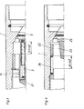
- Valve guides 14 , 15 in which valves 5, 6 are arranged axially displaceably are provided in the housing 1 of a coupling sleeve that is not pressurized, as well as in the housing 2 of a pressurized coupling plug.
- the valves 5, 6 are pressed onto their associated valve seat by springs 3, 4.
- the spring 3 of the valve 5 in the non-pressurized coupling half, the coupling sleeve is in this case stronger than the spring 4 in the opposite coupling half.
- valve 6 of the coupling plug is pressed by the strong spring 3 of the valve 5 of the coupling sleeve against a stop 9 formed by the valve guide 15.
- the valve 6 cannot be moved axially, with the result that the valve 5 is displaced into the coupling sleeve by the path S 1 + S 2 . Only when the pressure is equalized can the stronger spring 3 of the valve 5 then have an effect and also move the valve 6 into the open position shown in FIG. 2 against the stop 9 of the valve guide 15.
- the connecting coupling is constructed so that the free passage cross-section in the space 18 around the valve guide 14 of the coupling sleeve is greater than that of the chamber 1 7 about the valve guide 15 of the coupling plug and that this in turn is greater than the valve passage cross-section 13.
- the valves 5, 6 are designed together with their valve seats 10, 11 so that the valve passage cross section 13 over the entire distance 19, despite of the increasing diameter of the valves 5, 6 remains the same.
- the valve 5 is sharply offset on the side 12 facing the space 18 around the valve guide 14 in the coupling sleeve in order to achieve a sudden transition from the valve passage cross section 13 to the space 18 around the valve guide 14 of the coupling sleeve.
- valve passage cross-section 13 remains the same over the entire distance 19 due to the special shape of the valves 5, 6 and their valve seats 10, 11, no pressure changes take place here or no forces possibly displacing the valves 5, 6 act on these valves 5 , 6 a.
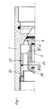
- FIG. 3 shows the embodiment in which the valve 5 is connected to a baffle plate 21 arranged behind the valve guide 14 .
- This baffle plate 21 is fully loaded in the flow direction 16, while it is covered in the opposite direction by the valve guide 14.
- the valve 25 is connected via struts 23 to an annular piston 22 which is guided in the housing 1 and is acted upon by a compression spring 24.
- the additional surface is formed by the annular piston 22 with its struts 23.
Landscapes
- Engineering & Computer Science (AREA)
- General Engineering & Computer Science (AREA)
- Mechanical Engineering (AREA)
- Check Valves (AREA)
- Safety Valves (AREA)
- Quick-Acting Or Multi-Walled Pipe Joints (AREA)
- Adhesive Tapes (AREA)
- Hydraulic Clutches, Magnetic Clutches, Fluid Clutches, And Fluid Joints (AREA)
Applications Claiming Priority (2)
| Application Number | Priority Date | Filing Date | Title |
|---|---|---|---|
| DE2741027 | 1977-09-12 | ||
| DE19772741027 DE2741027A1 (de) | 1977-09-12 | 1977-09-12 | Unter druck kuppelbare verbindungskupplung |
Publications (2)
| Publication Number | Publication Date |
|---|---|
| EP0001080A1 true EP0001080A1 (fr) | 1979-03-21 |
| EP0001080B1 EP0001080B1 (fr) | 1983-04-27 |
Family
ID=6018750
Family Applications (1)
| Application Number | Title | Priority Date | Filing Date |
|---|---|---|---|
| EP78100763A Expired EP0001080B1 (fr) | 1977-09-12 | 1978-08-28 | Raccord accouplable sous pression |
Country Status (10)
| Country | Link |
|---|---|
| US (1) | US4274441A (fr) |
| EP (1) | EP0001080B1 (fr) |
| AT (1) | AT367883B (fr) |
| DD (1) | DD138234A5 (fr) |
| DE (1) | DE2741027A1 (fr) |
| DK (1) | DK398578A (fr) |
| FI (1) | FI782686A7 (fr) |
| HU (1) | HU178351B (fr) |
| IT (1) | IT1098531B (fr) |
| NO (1) | NO783073L (fr) |
Families Citing this family (2)
| Publication number | Priority date | Publication date | Assignee | Title |
|---|---|---|---|---|
| EP0034312B1 (fr) * | 1980-02-14 | 1985-01-16 | Aeroquip GmbH | Accouplement à action rapide accouplable aussi sous pression |
| FR3129452B1 (fr) * | 2021-11-22 | 2024-06-14 | Akwel | Raccord de couplage à obturation rapide. |
Citations (6)
| Publication number | Priority date | Publication date | Assignee | Title |
|---|---|---|---|---|
| FR1248322A (fr) * | 1959-06-27 | 1960-10-31 | Frieseke & Hoepfner Gmbh | Dispositif d'accouplement pour appareils à fluide hydraulique sous pression |
| US3236251A (en) * | 1963-04-04 | 1966-02-22 | Hansen Mfg Co | Valve unit |
| CH491316A (de) * | 1968-05-02 | 1970-05-31 | Pedrolit Gmbh | Schlauchkupplung |
| DE2520393A1 (de) * | 1975-05-07 | 1976-11-25 | Eckerle Otto | Verbindungskupplung mit automatisch schliessbaren ventilen |
| US4036258A (en) * | 1975-01-08 | 1977-07-19 | Mannesmann Aktiengesellschaft | High speed shut off of conduits |
| DE2642724A1 (de) * | 1976-09-23 | 1978-03-30 | Fischer Wolf E | Unter druck kuppelbare verbindungskupplung |
Family Cites Families (7)
| Publication number | Priority date | Publication date | Assignee | Title |
|---|---|---|---|---|
| US2735696A (en) * | 1956-02-21 | Coupling | ||
| US2637572A (en) * | 1950-07-14 | 1953-05-05 | Us Army | Self-sealing coupling |
| US2706646A (en) * | 1951-07-02 | 1955-04-19 | Elmer T Olson | Coupler for hydraulic lines |
| US3348575A (en) * | 1965-08-16 | 1967-10-24 | Int Harvester Co | Hydraulically actuatable fluid coupling |
| US3367366A (en) * | 1965-10-11 | 1968-02-06 | Universal Oil Prod Co | Disconnect with minimum inclusion |
| US3791411A (en) * | 1972-08-18 | 1974-02-12 | B Bogeskov | Hydraulic coupler |
| CH626696A5 (fr) * | 1977-03-19 | 1981-11-30 | Argus Gmbh |
-
1977
- 1977-09-12 DE DE19772741027 patent/DE2741027A1/de not_active Ceased
-
1978
- 1978-08-22 AT AT0609378A patent/AT367883B/de active
- 1978-08-28 EP EP78100763A patent/EP0001080B1/fr not_active Expired
- 1978-09-01 FI FI782686A patent/FI782686A7/fi unknown
- 1978-09-04 HU HU78SE1911A patent/HU178351B/hu unknown
- 1978-09-05 US US05/939,863 patent/US4274441A/en not_active Expired - Lifetime
- 1978-09-07 DD DD78207688A patent/DD138234A5/xx unknown
- 1978-09-11 DK DK398578A patent/DK398578A/da not_active Application Discontinuation
- 1978-09-11 IT IT27521/78A patent/IT1098531B/it active
- 1978-09-11 NO NO783073A patent/NO783073L/no unknown
Patent Citations (6)
| Publication number | Priority date | Publication date | Assignee | Title |
|---|---|---|---|---|
| FR1248322A (fr) * | 1959-06-27 | 1960-10-31 | Frieseke & Hoepfner Gmbh | Dispositif d'accouplement pour appareils à fluide hydraulique sous pression |
| US3236251A (en) * | 1963-04-04 | 1966-02-22 | Hansen Mfg Co | Valve unit |
| CH491316A (de) * | 1968-05-02 | 1970-05-31 | Pedrolit Gmbh | Schlauchkupplung |
| US4036258A (en) * | 1975-01-08 | 1977-07-19 | Mannesmann Aktiengesellschaft | High speed shut off of conduits |
| DE2520393A1 (de) * | 1975-05-07 | 1976-11-25 | Eckerle Otto | Verbindungskupplung mit automatisch schliessbaren ventilen |
| DE2642724A1 (de) * | 1976-09-23 | 1978-03-30 | Fischer Wolf E | Unter druck kuppelbare verbindungskupplung |
Also Published As
| Publication number | Publication date |
|---|---|
| AT367883B (de) | 1982-08-10 |
| IT1098531B (it) | 1985-09-07 |
| EP0001080B1 (fr) | 1983-04-27 |
| FI782686A7 (fi) | 1979-03-13 |
| IT7827521A0 (it) | 1978-09-11 |
| DK398578A (da) | 1979-03-13 |
| ATA609378A (de) | 1981-12-15 |
| DD138234A5 (de) | 1979-10-17 |
| DE2741027A1 (de) | 1979-03-22 |
| NO783073L (no) | 1979-03-13 |
| US4274441A (en) | 1981-06-23 |
| HU178351B (en) | 1982-04-28 |
Similar Documents
| Publication | Publication Date | Title |
|---|---|---|
| DE3407878C1 (de) | Rueckschlagventil fuer die Stempel von Schreitausbaugestellen | |
| DE3039380A1 (de) | Vorrichtung zum verbinden einer druckfluessigkeitsquelle mit einem hydraulikmotor | |
| DE1256485B (de) | Hydraulischer Stossdaempfer | |
| DE2350390B2 (fr) | ||
| DE1675538A1 (de) | Ventilaggregat | |
| DE1525680B1 (de) | Ventilkupplungen fuer unter Druck stehende Schlauchleitungen | |
| DE1959764A1 (de) | Druckkompensierte Steuerventile fuer durch ein Druckmedium betaetigte Systeme | |
| DE1650325A1 (de) | Hydraulisch stabilisiertes,doppeltwirkendes,gesteuertes Absperrventil | |
| DE2513013C3 (de) | Hydraulisches Wegeventil | |
| DE1901359A1 (de) | Steuervorrichtung mit Differentialkolben und Schieber | |
| DE69407704T2 (de) | Durchflussregelventil | |
| DE3105284A1 (de) | Verzoegerungsabfuehlventil | |
| DE3341643A1 (de) | Vorgesteuertes druckentlastungs- und steuerventil | |
| DE3907378A1 (de) | Ventilanordnung zum gleichzeitigen oeffnen und absperren zweier getrennter zuleitungen fuer fluessige oder gasfoermige medien | |
| DE1425595B2 (de) | Einrichtung zur daempfung von druckstoessen mit einem nadelventil | |
| DE3218527C2 (fr) | ||
| DE2631922A1 (de) | Kombiniertes druckbegrenzungsventil und rueckschlagventil | |
| EP0001080B1 (fr) | Raccord accouplable sous pression | |
| DE3243182C2 (fr) | ||
| EP0278333A2 (fr) | Dispositif de commande pour un séparateur de tuyau | |
| DE69629171T2 (de) | Hydraulisches Absperrventil | |
| DE2642724C2 (de) | Kupplung zur Verbindung von Hydraulikleitungen | |
| DE4217121C2 (de) | Freikolben-Zylinder-Vorrichtung mit zwei verschiedenen Druckflüssigkeiten | |
| DE3828025A1 (de) | Daempfungssystem fuer fluid-zylinder | |
| DE1234465B (de) | Ventil mit einem selbsttaetig gegen die Stroemungsrichtung schliessenden Verschlussstueck |
Legal Events
| Date | Code | Title | Description |
|---|---|---|---|
| PUAI | Public reference made under article 153(3) epc to a published international application that has entered the european phase |
Free format text: ORIGINAL CODE: 0009012 |
|
| AK | Designated contracting states |
Designated state(s): BE CH FR GB LU NL SE |
|
| 17P | Request for examination filed | ||
| GRAA | (expected) grant |
Free format text: ORIGINAL CODE: 0009210 |
|
| AK | Designated contracting states |
Designated state(s): BE CH FR GB LU NL SE |
|
| PGFP | Annual fee paid to national office [announced via postgrant information from national office to epo] |
Ref country code: SE Payment date: 19830630 Year of fee payment: 6 |
|
| PGFP | Annual fee paid to national office [announced via postgrant information from national office to epo] |
Ref country code: LU Payment date: 19830803 Year of fee payment: 6 |
|
| ET | Fr: translation filed | ||
| PG25 | Lapsed in a contracting state [announced via postgrant information from national office to epo] |
Ref country code: LU Free format text: LAPSE BECAUSE OF NON-PAYMENT OF DUE FEES Effective date: 19830831 |
|
| PGFP | Annual fee paid to national office [announced via postgrant information from national office to epo] |
Ref country code: NL Payment date: 19830831 Year of fee payment: 6 Ref country code: CH Payment date: 19830831 Year of fee payment: 6 Ref country code: BE Payment date: 19830831 Year of fee payment: 6 |
|
| PGFP | Annual fee paid to national office [announced via postgrant information from national office to epo] |
Ref country code: FR Payment date: 19840828 Year of fee payment: 7 |
|
| PG25 | Lapsed in a contracting state [announced via postgrant information from national office to epo] |
Ref country code: SE Effective date: 19840829 |
|
| PG25 | Lapsed in a contracting state [announced via postgrant information from national office to epo] |
Ref country code: CH Effective date: 19840831 |
|
| REG | Reference to a national code |
Ref country code: FR Ref legal event code: TP |
|
| PG25 | Lapsed in a contracting state [announced via postgrant information from national office to epo] |
Ref country code: NL Effective date: 19850301 |
|
| NLV4 | Nl: lapsed or anulled due to non-payment of the annual fee | ||
| REG | Reference to a national code |
Ref country code: CH Ref legal event code: PL |
|
| GBPC | Gb: european patent ceased through non-payment of renewal fee | ||
| PG25 | Lapsed in a contracting state [announced via postgrant information from national office to epo] |
Ref country code: FR Free format text: LAPSE BECAUSE OF NON-PAYMENT OF DUE FEES Effective date: 19860430 |
|
| REG | Reference to a national code |
Ref country code: FR Ref legal event code: ST |
|
| PG25 | Lapsed in a contracting state [announced via postgrant information from national office to epo] |
Ref country code: GB Effective date: 19881117 |
|
| PG25 | Lapsed in a contracting state [announced via postgrant information from national office to epo] |
Ref country code: BE Effective date: 19890831 |
|
| EUG | Se: european patent has lapsed |
Ref document number: 78100763.8 Effective date: 19850612 |
|
| PLBE | No opposition filed within time limit |
Free format text: ORIGINAL CODE: 0009261 |
|
| STAA | Information on the status of an ep patent application or granted ep patent |
Free format text: STATUS: NO OPPOSITION FILED WITHIN TIME LIMIT |