EP0001232B1 - Vorrichtung zum Trocknen der Schlichte von Glasseidefäden oder dergleichen - Google Patents
Vorrichtung zum Trocknen der Schlichte von Glasseidefäden oder dergleichen Download PDFInfo
- Publication number
- EP0001232B1 EP0001232B1 EP78100808A EP78100808A EP0001232B1 EP 0001232 B1 EP0001232 B1 EP 0001232B1 EP 78100808 A EP78100808 A EP 78100808A EP 78100808 A EP78100808 A EP 78100808A EP 0001232 B1 EP0001232 B1 EP 0001232B1
- Authority
- EP
- European Patent Office
- Prior art keywords
- electrodes
- coil
- drying
- housing
- hot air
- Prior art date
- Legal status (The legal status is an assumption and is not a legal conclusion. Google has not performed a legal analysis and makes no representation as to the accuracy of the status listed.)
- Expired
Links
- 238000001035 drying Methods 0.000 title claims description 13
- 239000011521 glass Substances 0.000 title claims 2
- 238000004804 winding Methods 0.000 claims description 17
- 239000003365 glass fiber Substances 0.000 description 2
- 238000009833 condensation Methods 0.000 description 1
- 230000005494 condensation Effects 0.000 description 1
- 238000010276 construction Methods 0.000 description 1
- 230000000694 effects Effects 0.000 description 1
- 238000010292 electrical insulation Methods 0.000 description 1
- 239000004744 fabric Substances 0.000 description 1
- 239000000835 fiber Substances 0.000 description 1
- 238000010438 heat treatment Methods 0.000 description 1
- 239000011810 insulating material Substances 0.000 description 1
- 238000000034 method Methods 0.000 description 1
- 230000001105 regulatory effect Effects 0.000 description 1
- 238000004513 sizing Methods 0.000 description 1
- 239000004753 textile Substances 0.000 description 1
Images
Classifications
-
- F—MECHANICAL ENGINEERING; LIGHTING; HEATING; WEAPONS; BLASTING
- F26—DRYING
- F26B—DRYING SOLID MATERIALS OR OBJECTS BY REMOVING LIQUID THEREFROM
- F26B13/00—Machines and apparatus for drying fabrics, fibres, yarns, or other materials in long lengths, with progressive movement
- F26B13/001—Drying and oxidising yarns, ribbons or the like
-
- F—MECHANICAL ENGINEERING; LIGHTING; HEATING; WEAPONS; BLASTING
- F26—DRYING
- F26B—DRYING SOLID MATERIALS OR OBJECTS BY REMOVING LIQUID THEREFROM
- F26B3/00—Drying solid materials or objects by processes involving the application of heat
- F26B3/32—Drying solid materials or objects by processes involving the application of heat by development of heat within the materials or objects to be dried, e.g. by fermentation or other microbiological action
- F26B3/34—Drying solid materials or objects by processes involving the application of heat by development of heat within the materials or objects to be dried, e.g. by fermentation or other microbiological action by using electrical effects
- F26B3/343—Drying solid materials or objects by processes involving the application of heat by development of heat within the materials or objects to be dried, e.g. by fermentation or other microbiological action by using electrical effects in combination with convection
Definitions
- the invention relates to a device for drying the size of glass fiber threads, which are wound on winding machines to form a winding, wherein a series of electrodes of different potentials are arranged around the winding, the distances from the winding surface and, transversely to the longitudinal direction of the threads / above whose electrical power can be regulated.
- Drying devices of the type mentioned above have proven themselves from a technical and economic point of view for drying threads and, if appropriate, also fabric webs.
- the object of the present invention is to design a device of the type mentioned at the outset in such a way that the drying process is supported and the risk of electrical arcing on the electrodes can be reduced.
- the electrodes are surrounded by a housing extending to the gap near the winding, which is open to the surface of the winding and is blown into the hot air at over 100 ° C under pressure.
- the housing can advantageously consist of individual chambers which are connected to one another in the manner of hinges and each cover an electrode group.
- the housing and electrodes are then expediently adjusted together with the changing diameter of the winding.
- each chamber can be provided with a separate hot air supply line, but it is also possible to introduce the hot air into the chambers via holes in the electrodes.
- the thread 3 impregnated with size which consists of a large number of individual threads, runs in the direction of arrow 2 into the winding machine and is wound here into a roll 1.
- a plurality of rod electrodes 10 and 14 are distributed around the circumference of the winding 1 transversely to the longitudinal direction of the thread.
- the rod electrodes 10 and 14, which extend over the entire width of the winding 1, are alternately connected to different poles of the high-frequency source 9 and can be adjusted both in relation to one another and relative to the surface of the winding 1 in the direction of the double arrow 7.
- Intensive and controllable drying of the thread 3 can be achieved by the stray field that arises between the rod electrodes 10 and 14 in the longitudinal direction of the thread.
- 0.5 to 5 kilovolts per cm should be recommended as the field strength and about 10 MHz to 30 MHz, preferably about 15 MHz, as the frequency.
- the power of the high-frequency source 9 can be adjusted in accordance with the temperature measured with a temperature meter 6.
- the electrodes 10, 14 are surrounded by a housing 4, which consists of individual chambers 41 connected to one another in the manner of hinges 8, each of which covers an electrode group 10, 14.
- Each chamber 41 is connected to a separate hot air supply line 51, via which hot air 5 of over 100 ° under pressure, e.g. 1.5 atmospheres.
- the injected hot air 5 flows around the electrodes 10, 14 and flows out through the gap between the chambers 41 and the surface of the roll 1.
- the hot air both heats the electrodes and prevents moisture and / or sizing from reaching the electrodes. At the same time, additional drying of the winding surface is achieved.
- a sensor 11 which detects the diameter of the winding 1 and which acts on a central control device 12.
- This central control device 12 gives control commands to the individual drives 13 which move the individual electrodes 10, 14 along the curved or straight guideways 15 so that their distance 16 to the surface of the roll 1 and the mutual-Ab 17 was always the same or at least approximately the same.
- the gap s between the surface of the winding 1 and the chambers 41 mechanically connected to the electrodes also remains approximately constant, so that the hot air with the moisture components can escape through this gap.
- the housings themselves are made of flexible insulating material, so that they can follow the movements of the electrodes to a certain extent and at the same time cause electrical insulation between the individual electrodes of different potentials.
- the arrangement described above can not only be used for drying the size of glass fiber threads, but can also be used e.g. be used when drying textile fibers or the like.
Landscapes
- Engineering & Computer Science (AREA)
- Life Sciences & Earth Sciences (AREA)
- Microbiology (AREA)
- Mechanical Engineering (AREA)
- General Engineering & Computer Science (AREA)
- Textile Engineering (AREA)
- Health & Medical Sciences (AREA)
- Biomedical Technology (AREA)
- Biotechnology (AREA)
- Molecular Biology (AREA)
- Drying Of Solid Materials (AREA)
- Treatment Of Fiber Materials (AREA)
Description
- Die Erfindung bezieht sich auf eine Vorrichtung zum Trocknen der Schlichte von Glasseidefäden, die an Spulmaschinen zu einem Wikkel aufgewickelt werden, wobei quer zur Längsrichtung der Fäden auf dem Wickel eine Reihe von Elektroden unterschiedlichen Potentials um den Wickel angeordnet sind, deren Abstände von der Wickeloberfläche und/ober deren elektrische Leistung regelbar sind.
- Mit diesem Oberbegriff wird auf eine Anordnung Bezug genommen, wie sie beispielsweise im deutschen Patent 2 041 557 beschrieben ist. Eine Stellvorrichtung, mit der die Elektroden in Bezug aufeinander und zur Oberfläche des Wickels verstellt werden können, ist näher in der deutschen Offenlegungsschrift 2 220 520 beschrieben, die einen Zusatz zum vorstehend genannten Patent darstellt.
- Trocknungseinrichtungen der vorstehend genannten Art haben sich in technischer und wirtschaftlicher Hinsicht zur Trocknung von Fäden und gegebenenfalls auch von Stoffbahnen gut bewährt.
- Ein gewisses Problem stellen jedoch nach wie vor die beim Wickelvorgang abgeschleuderten Tropfen und die infolge des Trocknungseffektes austretenden Dampfschwaden dar, da es hierdurch zu elektrischen Überschlägen an den Elektroden kommen kann. Dies läßt sich auch nicht durch eine Vortrocknung ganz vermeiden.
- Die Aufgabe der vorliegenden Erfindung besteht darin, eine Vorrichtung der eingangs genannten Art so auszubilden, daß der Trocknungsvorgang unterstützt und die Gefahr von elektrischen Uberschlägen an den Elektroden verringert werden kann.
- Diese Aufgabe wird erfindungsgemäß dadurch gelöst, daß die Elektroden von einem bis auf Spaltnähe zum Wickel reichenden Gehäuse umgeben sind, das zur Oberfläche des Wickels hin offen ist und in das Heißluft von über 100° C unter Druck eingeblasen wird.
- Auf diese Weise wird der Wickel zusätzlich getrocknet, gleichzeitig werden aber durch die mit Überdruck eingeblasene Heißluft sowohl Tropfen- als auch Dampfschwaden über den Spalt fortgerissen, so daß Feuchte und/oder Schlichte sich nicht auf den Elektroden niederschlagen können. Ein weiterer Vorteil dieser Vorrichtung ist auch noch in der zusätzlichen Beheizung der Elektroden selbst zu sehen, da hierdurch eine Kondensation von Feuchte auf den Elektroden verhindert wird.
- Konstruktiv kann vorteilhafterweise das Gehäuse aus in Art von Scharnieren miteinander verbundenen Einzelkammern bestehen, die jeweils eine Elektrodengruppe überdecken. Zweckmäßigerweise werden dann mit sich änderndem Durchmesser des Wickels Gehäuse und Elektroden gemeinsam verstellt.
- Zur Zuführung der Heißluft kann jede Kammer mit einer gesonderten Heißluftzuleitung versehen werden, es ist aber auch möglich, die Heißluft selbst über Löcher in den Elektroden in die Kammern einzuführen.
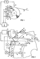
- Anhand eines in der-Zeichnung dargestellten Ausführungsbeispiels sei die Erfindung näher erläutert; es zeigen:
- Figur 1 das Prinzip der Trockenvorrichtung und
- Figur 2 Einzelheiten des Verstellmechanismus.
- Der mit Schlichte getränkte Faden 3, der aus einer Vielzahl von Einzelfädchen besteht, läuft in Richtung des Pfeiles 2 in die Spulmaschine und wird hier zu einem Wickel 1 aufgewickelt. Um den Umfang des Wickels 1 sind quer zur Fadenlängsrichtung eine Vielzahl von Stabelektroden 10 und 14 verteilt. Die sich über die gesamte Breite des Wickels 1 erstreckenden Stabelelektroden 10 und 14 sind abwechselnd an unterschiedliche Pole der Hochfrequenzquelle 9 angeschlossen und sind sowohl zueinander als auch relativ zur Oberfläche des Wickels 1 in Richtung des Doppelpfeiles 7 verstellbar. Durch das zwischen den Stabelelektroden 10 und 14 entstehende Streufeld in Fadenlängsrichtung ist eine intensive und steuerbare Trocknung des Fadens 3 erreichbar. Als Feldstärke dürften sich dabei 0,5 bis 5 Kilovolt pro cm empfehlen und als Frequenz cirka 10 MHz bis 30 MHz, vorzugsweisse ca. 15 MHz.
- Entsprechend der mit einem Temperaturmesser 6 erfaßten Temperatur ist die Leistung der Hochfrequenzquelle 9 einstellbar. Die Elektroden 10, 14 sind von einem Gehäuse 4 umgeben, das aus in der Art von Scharnieren 8 miteinander verbundenen Einzelkammern 41 besteht, die jeweils eine Elektrodengruppe 10, 14 überdecken.
- Jede Kammer 41 ist mit einer gesonderten Heißluftzuleitung 51 verbunden, über die Heißluft 5 von über 100° unter Druck, z.B. 1,5 Atmosphären, eingeblasen wird. Die eingeblasene Heißluft 5 umströmt die Elektroden 10, 14 und strömt durch den Spalt zwischen den Kammern 41 und der Oberfiäche des Wickels 1 ab. Durch die Heißluft werden sowohl die Elektroden geheizt als auch verhindert, daß Feuchtigkeit und/oder Schlichte an die Elektroden gelangt. Gleichzeitig wird auch noch eine zusätzliche Trocknung der Wickeloberfläche erreicht.
- Wie aus Figur 2 näher ersichtlich, ist ein den Durchmesser des Wickels 1 erfassender Fühler 11 vorgesehen, der auf ein Zentralsteuergerät 12 einwirkt. Dieses Zentralsteuergerät 12 gibt Steuerbefehle auf die einzelnen Antriebe 13, die die einzelnen Elektroden 10, 14 entlang der gekrümmten bzw. geraden Führungsbahnen 15 so verschieben, daß deren Abstand 16 zur Oberfläche des Wickels 1 und der gegenseitige-Abstand 17 stets gleich oder wenigstens annähernd gleich bleibt. Damit bleibt auch der Spalt s zwischen der Oberfläche des Wickels 1 und den mit den Elektroden mechanisch verbundenen Kammern 41 in etwa konstant, so daß durch diesen Spalt die Heißluft mit den Feuchteanteilen entweichen kann.
- Die Gehäuse selbst sind aus biegsamen Isolierstoff hergestellt, so daß sie den Bewegungen der Elektroden in bestimmten Maßen folgen können und gleichzeitig eine elektrische Isolation zwischen den einzelnen Elektroden unterschiedlichen Potentials bewirken. Die vorstehend beschriebene Anordnung kann nicht nur zur Trocknung der Schlichte von Glasseidefäden verwendet werden, sondern kann auch z.B. bei der Trocknung von Textilfasern oder dgl. verwendet werden.
Claims (5)
Applications Claiming Priority (2)
| Application Number | Priority Date | Filing Date | Title |
|---|---|---|---|
| DE2742086 | 1977-09-19 | ||
| DE19772742086 DE2742086A1 (de) | 1977-09-19 | 1977-09-19 | Vorrichtung zum trocknen der schlichte von glasseidefaeden o.dgl. |
Publications (2)
| Publication Number | Publication Date |
|---|---|
| EP0001232A1 EP0001232A1 (de) | 1979-04-04 |
| EP0001232B1 true EP0001232B1 (de) | 1980-07-23 |
Family
ID=6019304
Family Applications (1)
| Application Number | Title | Priority Date | Filing Date |
|---|---|---|---|
| EP78100808A Expired EP0001232B1 (de) | 1977-09-19 | 1978-09-01 | Vorrichtung zum Trocknen der Schlichte von Glasseidefäden oder dergleichen |
Country Status (3)
| Country | Link |
|---|---|
| US (1) | US4218830A (de) |
| EP (1) | EP0001232B1 (de) |
| DE (2) | DE2742086A1 (de) |
Families Citing this family (11)
| Publication number | Priority date | Publication date | Assignee | Title |
|---|---|---|---|---|
| US4397262A (en) * | 1980-10-06 | 1983-08-09 | Champion International Corporation | Apparatus for applying and drying sealing material to the seal flap of envelopes |
| US4440557A (en) * | 1982-12-20 | 1984-04-03 | Owens-Corning Fiberglas Corporation | Method and apparatus for forming and collecting continuous glass filaments |
| US4478625A (en) * | 1982-12-20 | 1984-10-23 | Owens-Corning Fiberglas Corporation | Apparatus for producing and collecting glass fibers |
| US4573402A (en) * | 1984-08-08 | 1986-03-04 | Rajeeva Sharma | Caliper control system and method |
| US4638571A (en) * | 1986-04-02 | 1987-01-27 | Cook William A | Radio frequency nozzle bar dryer |
| US4727655A (en) * | 1987-02-02 | 1988-03-01 | Amjo Infra Red Dryers, Inc. | Heat lamp assembly with air duct |
| US5052125A (en) * | 1990-09-26 | 1991-10-01 | Ppg Industries, Inc. | Method and apparatus for supporting strand |
| US5197202A (en) * | 1990-09-26 | 1993-03-30 | Ppg Industries, Inc. | Method and apparatus for drying and curing a coated strand |
| DE4106573C1 (en) * | 1991-03-01 | 1992-07-16 | Josef Prof. Dr.-Ing. 8200 Rosenheim De Gefahrt | Water-based wood varnish drier - applies capacitative stray field to horizontal conveyor of low dielectric loss carrying flat wood pieces or wooden surfaces greater than 500 mm in width |
| FR2729570A1 (fr) * | 1995-01-24 | 1996-07-26 | Idm Immuno Designed Molecules | Procede de preparation de macrophages actives, trousses et compositions pour la mise en oeuvre de ce procede |
| WO2021058586A1 (en) | 2019-09-27 | 2021-04-01 | Ocv Intellectual Capital, Llc | Process for drying wet glass fibre forming packages |
Family Cites Families (11)
| Publication number | Priority date | Publication date | Assignee | Title |
|---|---|---|---|---|
| US3872603A (en) * | 1968-01-30 | 1975-03-25 | Varian Associates | Apparatus for drying materials employing spaced microwave heating and transverse-flow moisture flushing stations |
| DE1903005A1 (de) * | 1969-01-22 | 1970-08-06 | Siemens Ag | Vorrichtung zum kapazitiven Erwaermen zu trocknender zylindrischer oder prismatischer Koerper,z.B.Spinnkuchen |
| US3740257A (en) * | 1971-09-21 | 1973-06-19 | Ppg Industries Inc | Process and apparatus for dielectric heat drying elastomer coated glass fibers |
| JPS52587B2 (de) * | 1972-04-11 | 1977-01-08 | ||
| DE2220520C3 (de) * | 1972-04-26 | 1978-04-13 | Siemens Ag, 1000 Berlin Und 8000 Muenchen | Vorrichtung zum Trocknen der Schlichte von Glasseidefäden |
| DE2421570A1 (de) * | 1974-05-03 | 1975-11-06 | Siemens Ag | Verfahren und vorrichtung zur hochfrequenzbehandlung von feuchtem gut |
| US4014732A (en) * | 1974-06-01 | 1977-03-29 | Firma Mohndruck, Reinhard Mohn Ohg | Device for drying and setting the adhesive on backs of books |
| GB1486415A (en) * | 1974-09-16 | 1977-09-21 | Wira & Mather | Method and means for drying objects of or containing textile fibres |
| FR2299443A1 (fr) * | 1974-10-11 | 1976-08-27 | Mhm Electronic | Dispositif de sechage et de traitement thermique de fils textiles par pertes dielectriques |
| US3953701A (en) * | 1975-03-24 | 1976-04-27 | Radio Frequency Co., Inc. | Radio frequency heating and ventilating electrode system |
| US4048917A (en) * | 1975-09-26 | 1977-09-20 | Sun Chemical Corporation | Continuous motion printing apparatus |
-
1977
- 1977-09-19 DE DE19772742086 patent/DE2742086A1/de not_active Withdrawn
-
1978
- 1978-09-01 EP EP78100808A patent/EP0001232B1/de not_active Expired
- 1978-09-01 DE DE7878100808T patent/DE2860083D1/de not_active Expired
- 1978-09-18 US US05/943,303 patent/US4218830A/en not_active Expired - Lifetime
Also Published As
| Publication number | Publication date |
|---|---|
| EP0001232A1 (de) | 1979-04-04 |
| DE2860083D1 (en) | 1980-11-13 |
| US4218830A (en) | 1980-08-26 |
| DE2742086A1 (de) | 1979-03-29 |
Similar Documents
| Publication | Publication Date | Title |
|---|---|---|
| EP0001232B1 (de) | Vorrichtung zum Trocknen der Schlichte von Glasseidefäden oder dergleichen | |
| DE69303711T2 (de) | Anlage und verfahren zur herstellung von vliesstoff aus thermoplastischen filamenten | |
| DE2424302C2 (de) | Verfahren zum Regeln der Fadenspannung | |
| EP3132074B1 (de) | Verfahren und vorrichtung zum spreizen eines faserstrangs | |
| DE2841371C2 (de) | Einrichtung zur Führung einer Papierbahn im kapazitiven Hochfrequenztrockner | |
| DE2448217A1 (de) | Verfahren zur herstellung von faserverstaerkten thermoplastischen materialien | |
| EP0128397B1 (de) | Kapazitiver Hochfrequenz-Durchlaufofen | |
| DE2731062A1 (de) | Verfahren und vorrichtung zur behandlung von faeden | |
| DE19841638A1 (de) | Feuchteprofilierung | |
| EP3201376A1 (de) | Schmelzspinnvorrichtung | |
| EP1959049B1 (de) | Tunnelfinisher | |
| DE4334585A1 (de) | Verfahren zum Regulieren der Feuchtigkeit von zu kämmendem Fasermaterial | |
| EP0105174B1 (de) | Kapazitiver Hochfrequenzdurchlaufofen | |
| DE3202923C2 (de) | ||
| DE2248808A1 (de) | Vorrichtung zur falschdrall-texturierung und nachfixierung von aus thermoplastischem synthetischem material bestehenden garnen in kontinuierlicher arbeitsweise | |
| DE1206718B (de) | Trockenvorrichtung fuer Faserstoffbahnen | |
| DE2132844C3 (de) | Trockenvorrichtung für eine Webmaschine | |
| DE2036489C3 (de) | Kapazitiver Hochfrequenzofen zum Trocknen von gefalteten Chemiefaserkabeln | |
| DE4106573C1 (en) | Water-based wood varnish drier - applies capacitative stray field to horizontal conveyor of low dielectric loss carrying flat wood pieces or wooden surfaces greater than 500 mm in width | |
| DE2556487C3 (de) | Vorrichtung zum kontinuierlichen Imprägnieren von Textilien in Strangform | |
| DE2041557C3 (de) | Vorrichtung zum Trocknen der Schlichte von Glasseidefäden | |
| DE1292548B (de) | Vorrichtung zur Herstellung von Bahnen oder Matten aus Fasern, vornehmlich Glasfasern | |
| DE19819051A1 (de) | Verfahren und Vorrichtung zum Behandeln schlauchförmiger Maschenware | |
| DE1295353B (de) | Vorrichtung zum Befeuchten von Papierbahnen od. dgl. | |
| DE2242166A1 (de) | Einrichtung zum erwaermen von endlosen faeden, garnen oder baendchen |
Legal Events
| Date | Code | Title | Description |
|---|---|---|---|
| PUAI | Public reference made under article 153(3) epc to a published international application that has entered the european phase |
Free format text: ORIGINAL CODE: 0009012 |
|
| AK | Designated contracting states |
Designated state(s): BE DE FR GB |
|
| 17P | Request for examination filed | ||
| GRAA | (expected) grant |
Free format text: ORIGINAL CODE: 0009210 |
|
| AK | Designated contracting states |
Designated state(s): BE DE FR GB |
|
| REF | Corresponds to: |
Ref document number: 2860083 Country of ref document: DE Date of ref document: 19801113 |
|
| PGFP | Annual fee paid to national office [announced via postgrant information from national office to epo] |
Ref country code: FR Payment date: 19840920 Year of fee payment: 7 |
|
| PGFP | Annual fee paid to national office [announced via postgrant information from national office to epo] |
Ref country code: BE Payment date: 19840930 Year of fee payment: 7 |
|
| PGFP | Annual fee paid to national office [announced via postgrant information from national office to epo] |
Ref country code: GB Payment date: 19890831 Year of fee payment: 12 |
|
| PG25 | Lapsed in a contracting state [announced via postgrant information from national office to epo] |
Ref country code: BE Effective date: 19890930 |
|
| BERE | Be: lapsed |
Owner name: SIEMENS A.G. BERLIN UND MUNCHEN Effective date: 19890930 |
|
| PG25 | Lapsed in a contracting state [announced via postgrant information from national office to epo] |
Ref country code: FR Effective date: 19900531 |
|
| REG | Reference to a national code |
Ref country code: FR Ref legal event code: ST |
|
| PG25 | Lapsed in a contracting state [announced via postgrant information from national office to epo] |
Ref country code: GB Effective date: 19900901 |
|
| GBPC | Gb: european patent ceased through non-payment of renewal fee | ||
| PGFP | Annual fee paid to national office [announced via postgrant information from national office to epo] |
Ref country code: DE Payment date: 19910912 Year of fee payment: 14 |
|
| PG25 | Lapsed in a contracting state [announced via postgrant information from national office to epo] |
Ref country code: DE Effective date: 19930602 |
|
| PLBE | No opposition filed within time limit |
Free format text: ORIGINAL CODE: 0009261 |
|
| STAA | Information on the status of an ep patent application or granted ep patent |
Free format text: STATUS: NO OPPOSITION FILED WITHIN TIME LIMIT |