EP0001342A1 - Equipement prenant appui sur une poutre - Google Patents
Equipement prenant appui sur une poutre Download PDFInfo
- Publication number
- EP0001342A1 EP0001342A1 EP78300376A EP78300376A EP0001342A1 EP 0001342 A1 EP0001342 A1 EP 0001342A1 EP 78300376 A EP78300376 A EP 78300376A EP 78300376 A EP78300376 A EP 78300376A EP 0001342 A1 EP0001342 A1 EP 0001342A1
- Authority
- EP
- European Patent Office
- Prior art keywords
- main body
- clamp
- screw
- scaffold tube
- fitting
- Prior art date
- Legal status (The legal status is an assumption and is not a legal conclusion. Google has not performed a legal analysis and makes no representation as to the accuracy of the status listed.)
- Granted
Links
- 229910000831 Steel Inorganic materials 0.000 claims description 3
- 239000010959 steel Substances 0.000 claims description 3
- 238000010276 construction Methods 0.000 description 3
- 239000000463 material Substances 0.000 description 2
- 229910001209 Low-carbon steel Inorganic materials 0.000 description 1
- 238000012423 maintenance Methods 0.000 description 1
- 238000012986 modification Methods 0.000 description 1
- 230000004048 modification Effects 0.000 description 1
- 238000010422 painting Methods 0.000 description 1
Images





Classifications
-
- E—FIXED CONSTRUCTIONS
- E04—BUILDING
- E04G—SCAFFOLDING; FORMS; SHUTTERING; BUILDING IMPLEMENTS OR AIDS, OR THEIR USE; HANDLING BUILDING MATERIALS ON THE SITE; REPAIRING, BREAKING-UP OR OTHER WORK ON EXISTING BUILDINGS
- E04G3/00—Scaffolds essentially supported by building constructions, e.g. adjustable in height
- E04G3/22—Scaffolds essentially supported by building constructions, e.g. adjustable in height supported by roofs or ceilings
-
- E—FIXED CONSTRUCTIONS
- E04—BUILDING
- E04G—SCAFFOLDING; FORMS; SHUTTERING; BUILDING IMPLEMENTS OR AIDS, OR THEIR USE; HANDLING BUILDING MATERIALS ON THE SITE; REPAIRING, BREAKING-UP OR OTHER WORK ON EXISTING BUILDINGS
- E04G3/00—Scaffolds essentially supported by building constructions, e.g. adjustable in height
- E04G3/28—Mobile scaffolds; Scaffolds with mobile platforms
-
- E—FIXED CONSTRUCTIONS
- E04—BUILDING
- E04G—SCAFFOLDING; FORMS; SHUTTERING; BUILDING IMPLEMENTS OR AIDS, OR THEIR USE; HANDLING BUILDING MATERIALS ON THE SITE; REPAIRING, BREAKING-UP OR OTHER WORK ON EXISTING BUILDINGS
- E04G5/00—Component parts or accessories for scaffolds
- E04G5/04—Means for fastening, supporting, or bracing scaffolds on or against building constructions
- E04G5/045—Means for fastening, supporting, or bracing scaffolds on or against building constructions for fastening scaffoldings on profiles, e.g. I or H profiles
Definitions
- This invention relates to the attachment of scaffolding platforms, workmen's platforms or cradles and the like to flangsd girders of steel or like material and is particularly concerned with fittings for securing scaffolding to such girders.
- the present invention aims to provide a fitting which can be used to clamp a scaffold tube to a flanged girder, the scaffold tube forming part of a workmen's platform or cradle whereby said platform can be secured directly to the girder.
- a fitting adapted to be secured to a length of scaffold tube and to clamp said scaffold tube to a girder
- said fitting comprising a main body, a clamp pivotally mounted on the main body, said clamp and main body being so shaped as to receive and clamp between them a length of scaffold tube, the main body further being so shaped that the vertical load of the scaffold tube is borne substantially entirely by said main body, and a portion of said main body extanding at an end remote from the clamp in a direction substantially at right angles to the major length of the main body, a screw being provided which is engageable with a flange on a girder whereby a length of scaffold tube fitted with said fitting can be clamped to a flanged girder.
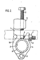
- the fitting 10 comprises a main body 1 having, adjacent one end, an arcuate recess 2 and on which one end of a latch or clamp 4 is pivotally mounted by means of a rivet 3.
- a latch bolt 6 is also pivotally mounted on the main body 1 and is receivable in a slot 5 in the other end of the clamp 4.
- the latch bolt 6 is screw-threaded along at least part of its length and a nut 7 and washer 8 are provided thereon.
- the other end of the main body 1 is curved from the axis of the major portion of the length of said body and terminates in a part 11 extending substantially at right angles to said axis.
- the part 11 is provided with a screw-threaded bore for receiving a screw 12.
- the fitting is secured to a length of scaffold tube 9 by engaging the arcuate recess 2 on said scaffold tube 9 and pivoting the clamp 4 into engagement with said scaffold tube.
- the latch bolt 6 is then allowed to drop into the slot 5 in the clamp 4 and the nut 7 turned until the body 1 and clamp 4 are clamped to the scaffold tube in an immovable manner.
- the fitting is then ready for the part 11 of the main body 1 to be hooked over the flange 13 of a flanged girder.
- the screw 12 is then turned to draw the scaffold tube 9 into engagement with the underside of the flange 13.
- the vertical load from the scaffold tube 9 is transferrsd via the lug rstaining the rivet 3, into the main body 1.
- the latch bolt is only subjected to loads from the fitting being clamped onto the scaffold tube 9.
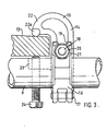
- the fitting 10 comprises a main body 14 having adjacent one end an arcuate recess 15 and on which one end of a latch or clamp 16 is pivotally mounted by means of a rivet 17.
- a latch bolt 18 pivotally mounted on the main body 14 is receivable in a slot 19 in the other end of the clamp 16.
- Part of the langth of the latch bolt 18 is screw-threaded for receiving a nut 20, a washer 21 being interposed between the nut 21 and clamp 16.
- the other end of the main body 14 is curved from the axis of the major portion of the length of said body and terminates in a part 22 eactending substantially at right angles to said axis.
- the end of said part 22 is provided with a bar-like projection 22a the longitudinal axis of which is substantially perpendicular to said axis of the main body as well as to the remainder of part 22.
- the projection 22a is intended to rest on the flange 13 of a flanged girder.
- a lug 23 which is alianed with the part 22 but spaced therefrom.
- the lug 23 is provided with a screw-threaded bore for receiving a screw 24.
- the fitting shown in Figures 3 and 4 can be secured to a length of scaffold tube 9 by engaging the arcuate recess 15 on the scaffold tube and pivoting the clamp 16 into engagement with the said scaffold tube.
- the latch bolt 18 is then allowed to drop into the slot 19 in the clamp 16 and the nut 20 turned until the main body 14 and clamp 16 are clamped to the scaffold tube in an immovable manner.
- the part 22 can then be hooked over the flange 13 of a flanged girder so that the projection 22a bears on said flange and the screw 24 turned to clamp the fitting to the flange 13.
- the vertical load from the scaffold tube 9 is transferred to the main body 14 via the lug retaining the rivet 17 so that the latch bolt is subjected only to the load of the fitting being clamped onto the scaffold tube.
- the load of the scaffold tube and fitting is borne by the part 22 and its projection 22a, the screw 24 serving merely to secure the fitting onto the girder and not being subjected to direct load.
- the main body 1 or 14 and latch or clamp 4 or 16 are preferably made of drop forged steel while the bolt 6 or 18 and screw 12 or 24 are preferably made of mild steel although other materials may be used if desired.
- Figures 5 and 6 show the manner in which fittings according to the invention can be used to suspend a working platform from a series of flanged girders forming the steelwork of, for example, a bridge or roof in order to gain access for painting or maintenance work for example.
- a single scaffold tube 9 ia secured to the flanges 13 of two parallelly- extending girders 25 and 26 by two fittings 10.
- a aeries of vertical scaffold tubes 27 are secured at spaced intervals to the scaffold tube 9 and a horizontal scaffold tube 28 is secured to the scaffold tubes 27 to extend parallel to the scaffold tube 9 to form a framework.
- This framework is secured to a like framework 29 ( Figure 6) by further horizontal scaffold tubes 30, 31 and 32, the tubes 32 being interconnected between the two frameworks by a transversely extending scaffold tube 33.
- Timber boards 34 are laid on the scaffold tubes 28 and 33 to form a working platform. Additional vertical boards 35 serve as toe boards and the scaffold tubes 31 serve as hand rails.
- the platform may be extended further by other frameworks 29 as shown in Figure 6.
- Figure 7 shows an example of a cantilevered scaffold which can be used where areas to be painted or maintained are near steelwork to which a working platform can be fixed by means of fittings 10 according to the invention.
- the boards 34 are placed directly on a series of scaffold tubes 9 to which vertical tubes 27 are secured for the location of toe boards 35 and hand rails 31.
- the platform can be braced by means of struts 36 bearing on the lower flange of an I-section girder 37 to the upper flange of which the fittings 10 are secured.
- Adjacent struts 36 are connected together by scaffold tubes 38 and adjacent scaffold tubes 9 are connected together by scaffold tubes 39.
- the fittings 10 are secured to the lower flange of I-section girder 37.
- the struts 36, scaffold tubes 38, one set of the vertical scaffold tubes 27 and one hand rail 31 can be dispensed with.
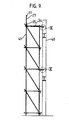
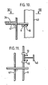
- Figures 9 to 11 show how fittings according to the invention can be used for tieing scaffolding to steelwork.
- Two fittings 10 are clamped to a vertical I-section girder 40 as shown in Figures 10 and 11 and scaffolding 41 is secured to the scaffold tubes 9 which are clamped to the girder by the fittings 10.
- Figures 12 and 13 show how fittings according to the invention can be used to secure scaffold tubes 9 serving as hand rails to columns consisting of vertical I-aection girders 42 to which are secured horizontal girders 43 which carry a floor level 44 of an unfinished building.
- the hand rails can be readily fitted and provide safer working conditions for workmen on the floor level 44.
- Figure 14 shows an arrangement for erecting a platform scaffold which is similar to the arrangement shown in Figure 7 except that in this case the scaffold tube 9 is secured to the upper flanges of two I-section girders 37 and 45 extending parallel to each other. In this case, only one fitting 10 is required to secure the scaffold tube 9 to each girder and to prevent movement of the scaffold tube 9 along the girders 37 and 45.
Landscapes
- Engineering & Computer Science (AREA)
- Architecture (AREA)
- Mechanical Engineering (AREA)
- Civil Engineering (AREA)
- Structural Engineering (AREA)
- Mutual Connection Of Rods And Tubes (AREA)
- Bridges Or Land Bridges (AREA)
Applications Claiming Priority (2)
| Application Number | Priority Date | Filing Date | Title |
|---|---|---|---|
| GB38960/77A GB1598788A (en) | 1977-09-19 | 1977-09-19 | Girder fittings |
| GB3896077 | 1978-05-22 |
Publications (2)
| Publication Number | Publication Date |
|---|---|
| EP0001342A1 true EP0001342A1 (fr) | 1979-04-04 |
| EP0001342B1 EP0001342B1 (fr) | 1981-08-05 |
Family
ID=10406759
Family Applications (1)
| Application Number | Title | Priority Date | Filing Date |
|---|---|---|---|
| EP78300376A Expired EP0001342B1 (fr) | 1977-09-19 | 1978-09-12 | Equipement prenant appui sur une poutre |
Country Status (3)
| Country | Link |
|---|---|
| EP (1) | EP0001342B1 (fr) |
| CA (1) | CA1126793A (fr) |
| GB (1) | GB1598788A (fr) |
Cited By (2)
| Publication number | Priority date | Publication date | Assignee | Title |
|---|---|---|---|---|
| EP0424417A4 (en) * | 1988-07-11 | 1991-06-19 | Cornelis Johannes Griek | A stanchion assembly |
| AU626247B3 (en) * | 1988-07-11 | 1992-06-04 | Dgs Property Pty Ltd | A stanchion assembly |
Families Citing this family (3)
| Publication number | Priority date | Publication date | Assignee | Title |
|---|---|---|---|---|
| GB2132679B (en) * | 1982-11-06 | 1986-03-05 | Burton Delingpole & Co Ltd | Scaffolding fitting |
| GB2158139B (en) * | 1984-05-01 | 1988-01-13 | London & Midland Drop Forging | Scaffolding clamp |
| GB2276414B (en) * | 1993-03-27 | 1996-05-15 | Edward Joseph Russell Campbell | Scaffolding bracket |
Citations (3)
| Publication number | Priority date | Publication date | Assignee | Title |
|---|---|---|---|---|
| US1710693A (en) * | 1928-01-18 | 1929-04-30 | American Safety Device Co | Clamp |
| US2165221A (en) * | 1936-07-03 | 1939-07-11 | Burton John | Scaffolding clamp |
| FR2346523A1 (fr) * | 1976-04-02 | 1977-10-28 | North Western Scaffolding | Ferrure pour echafaudage tubulaire |
-
1977
- 1977-09-19 GB GB38960/77A patent/GB1598788A/en not_active Expired
-
1978
- 1978-09-08 CA CA310,989A patent/CA1126793A/fr not_active Expired
- 1978-09-12 EP EP78300376A patent/EP0001342B1/fr not_active Expired
Patent Citations (3)
| Publication number | Priority date | Publication date | Assignee | Title |
|---|---|---|---|---|
| US1710693A (en) * | 1928-01-18 | 1929-04-30 | American Safety Device Co | Clamp |
| US2165221A (en) * | 1936-07-03 | 1939-07-11 | Burton John | Scaffolding clamp |
| FR2346523A1 (fr) * | 1976-04-02 | 1977-10-28 | North Western Scaffolding | Ferrure pour echafaudage tubulaire |
Cited By (3)
| Publication number | Priority date | Publication date | Assignee | Title |
|---|---|---|---|---|
| EP0424417A4 (en) * | 1988-07-11 | 1991-06-19 | Cornelis Johannes Griek | A stanchion assembly |
| AU626247B3 (en) * | 1988-07-11 | 1992-06-04 | Dgs Property Pty Ltd | A stanchion assembly |
| US5353891A (en) * | 1988-07-11 | 1994-10-11 | Dgs Property Pty. Ltd. | Stanchion assembly |
Also Published As
| Publication number | Publication date |
|---|---|
| EP0001342B1 (fr) | 1981-08-05 |
| CA1126793A (fr) | 1982-06-29 |
| GB1598788A (en) | 1981-09-23 |
Similar Documents
| Publication | Publication Date | Title |
|---|---|---|
| US6666298B2 (en) | Hanging scaffold support | |
| US7028990B2 (en) | Temporary rooftop and stairway safety rail system | |
| US5664391A (en) | Roof anchor and hanging scaffold system | |
| US4193708A (en) | Girder clamp | |
| US3084761A (en) | Scaffold | |
| WO1991009191A1 (fr) | Dispositif de support de structures | |
| US2201608A (en) | Scaffolding | |
| US4200955A (en) | Girder roller fittings | |
| EP1878850B1 (fr) | Système d'échafaudage | |
| EP0001342A1 (fr) | Equipement prenant appui sur une poutre | |
| US8794381B2 (en) | Fittings for builders' trestles | |
| US4392550A (en) | Scaffolding arrangement | |
| JPH0448274Y2 (fr) | ||
| CN210767926U (zh) | 安全防护平台 | |
| CA3010470A1 (fr) | Systeme d'echafaudage modulaire | |
| EP0497861B1 (fr) | Echaffaudage suspendu | |
| GB1568355A (en) | Building platform structures | |
| JPS6350343Y2 (fr) | ||
| CN111236607A (zh) | 一种超高层钢管柱操作平台及其拆装方法 | |
| JPS6030760A (ja) | 工事用可搬式歩廊 | |
| CA1163660A (fr) | Echafaudage | |
| IE81006B1 (en) | Walkway system | |
| CN211341741U (zh) | 一种龙骨连接件及一种建筑模板结构 | |
| GB2273953A (en) | Scaffold plank retainer | |
| SU711260A1 (ru) | Консольный кондуктор дл монтажа каркасно-панельных зданий с колоннами |
Legal Events
| Date | Code | Title | Description |
|---|---|---|---|
| PUAI | Public reference made under article 153(3) epc to a published international application that has entered the european phase |
Free format text: ORIGINAL CODE: 0009012 |
|
| AK | Designated contracting states |
Designated state(s): BE CH DE FR LU NL SE |
|
| 17P | Request for examination filed | ||
| GRAA | (expected) grant |
Free format text: ORIGINAL CODE: 0009210 |
|
| AK | Designated contracting states |
Designated state(s): BE CH DE FR LU NL SE |
|
| PG25 | Lapsed in a contracting state [announced via postgrant information from national office to epo] |
Ref country code: LU Free format text: LAPSE BECAUSE OF NON-PAYMENT OF DUE FEES Effective date: 19810930 |
|
| REF | Corresponds to: |
Ref document number: 2860904 Country of ref document: DE Date of ref document: 19811105 |
|
| PGFP | Annual fee paid to national office [announced via postgrant information from national office to epo] |
Ref country code: DE Payment date: 19830819 Year of fee payment: 6 |
|
| PGFP | Annual fee paid to national office [announced via postgrant information from national office to epo] |
Ref country code: LU Payment date: 19830824 Year of fee payment: 6 |
|
| PGFP | Annual fee paid to national office [announced via postgrant information from national office to epo] |
Ref country code: SE Payment date: 19830831 Year of fee payment: 6 Ref country code: BE Payment date: 19830831 Year of fee payment: 6 |
|
| PGFP | Annual fee paid to national office [announced via postgrant information from national office to epo] |
Ref country code: FR Payment date: 19830927 Year of fee payment: 6 |
|
| PGFP | Annual fee paid to national office [announced via postgrant information from national office to epo] |
Ref country code: NL Payment date: 19830930 Year of fee payment: 6 Ref country code: CH Payment date: 19830930 Year of fee payment: 6 |
|
| PG25 | Lapsed in a contracting state [announced via postgrant information from national office to epo] |
Ref country code: SE Effective date: 19840913 |
|
| PG25 | Lapsed in a contracting state [announced via postgrant information from national office to epo] |
Ref country code: CH Effective date: 19840930 Ref country code: BE Effective date: 19840930 |
|
| BERE | Be: lapsed |
Owner name: DEBORAH SERVICES LTD Effective date: 19840912 |
|
| PG25 | Lapsed in a contracting state [announced via postgrant information from national office to epo] |
Ref country code: NL Effective date: 19850401 |
|
| NLV4 | Nl: lapsed or anulled due to non-payment of the annual fee | ||
| PG25 | Lapsed in a contracting state [announced via postgrant information from national office to epo] |
Ref country code: FR Free format text: LAPSE BECAUSE OF NON-PAYMENT OF DUE FEES Effective date: 19850531 |
|
| REG | Reference to a national code |
Ref country code: CH Ref legal event code: PL |
|
| PG25 | Lapsed in a contracting state [announced via postgrant information from national office to epo] |
Ref country code: DE Effective date: 19850601 |
|
| REG | Reference to a national code |
Ref country code: FR Ref legal event code: ST |
|
| EUG | Se: european patent has lapsed |
Ref document number: 78300376.7 Effective date: 19850617 |
|
| PLBE | No opposition filed within time limit |
Free format text: ORIGINAL CODE: 0009261 |
|
| STAA | Information on the status of an ep patent application or granted ep patent |
Free format text: STATUS: NO OPPOSITION FILED WITHIN TIME LIMIT |