EP0001348A1 - Zahnradgetriebe - Google Patents
Zahnradgetriebe Download PDFInfo
- Publication number
- EP0001348A1 EP0001348A1 EP78300396A EP78300396A EP0001348A1 EP 0001348 A1 EP0001348 A1 EP 0001348A1 EP 78300396 A EP78300396 A EP 78300396A EP 78300396 A EP78300396 A EP 78300396A EP 0001348 A1 EP0001348 A1 EP 0001348A1
- Authority
- EP
- European Patent Office
- Prior art keywords
- gear
- input shaft
- coupling
- transmission
- output shaft
- Prior art date
- Legal status (The legal status is an assumption and is not a legal conclusion. Google has not performed a legal analysis and makes no representation as to the accuracy of the status listed.)
- Withdrawn
Links
- 230000005540 biological transmission Effects 0.000 title claims abstract description 57
- 230000008878 coupling Effects 0.000 claims abstract description 23
- 238000010168 coupling process Methods 0.000 claims abstract description 23
- 238000005859 coupling reaction Methods 0.000 claims abstract description 23
- 230000002441 reversible effect Effects 0.000 claims abstract description 22
- 230000009467 reduction Effects 0.000 claims description 18
- 238000010276 construction Methods 0.000 abstract description 3
- 230000007246 mechanism Effects 0.000 description 34
- 230000008859 change Effects 0.000 description 3
- 239000007787 solid Substances 0.000 description 3
- 230000000694 effects Effects 0.000 description 2
- 238000004519 manufacturing process Methods 0.000 description 2
- 238000010521 absorption reaction Methods 0.000 description 1
- 230000008901 benefit Effects 0.000 description 1
- 239000012530 fluid Substances 0.000 description 1
- 238000012423 maintenance Methods 0.000 description 1
- 238000000034 method Methods 0.000 description 1
- 230000004044 response Effects 0.000 description 1
Images

Classifications
-
- B—PERFORMING OPERATIONS; TRANSPORTING
- B63—SHIPS OR OTHER WATERBORNE VESSELS; RELATED EQUIPMENT
- B63H—MARINE PROPULSION OR STEERING
- B63H23/00—Transmitting power from propulsion power plant to propulsive elements
- B63H23/02—Transmitting power from propulsion power plant to propulsive elements with mechanical gearing
- B63H23/08—Transmitting power from propulsion power plant to propulsive elements with mechanical gearing with provision for reversing drive
-
- F—MECHANICAL ENGINEERING; LIGHTING; HEATING; WEAPONS; BLASTING
- F16—ENGINEERING ELEMENTS AND UNITS; GENERAL MEASURES FOR PRODUCING AND MAINTAINING EFFECTIVE FUNCTIONING OF MACHINES OR INSTALLATIONS; THERMAL INSULATION IN GENERAL
- F16H—GEARING
- F16H3/00—Toothed gearings for conveying rotary motion with variable gear ratio or for reversing rotary motion
- F16H3/44—Toothed gearings for conveying rotary motion with variable gear ratio or for reversing rotary motion using gears having orbital motion
- F16H3/46—Gearings having only two central gears, connected by orbital gears
- F16H3/60—Gearings for reversal only
Definitions
- This invention relates to high-power gear transmissions, such as may be used in marine applications.
- a further means of reversing the motion of a propeller- driven ship is to use a propeller the pitch of which may be controlled.
- controllable pitch propellers require extensive complex controlling equipment needing considerable maintenance and such systems have proved unreliable where high power transmission is involved.
- the object of the present invention to provide a high power gear transmission which has a simple, compact construction and which avoids the large loss of momentum energy associated with the prior art transmissions.
- a gear transmission comprising an input shaft, an epicyclic gear arrangement having its sun pinion fast for rotation with said input shaft, and an output shaft coupled for rotation in dependence upon rotation of a member that supports the annulus gear of the epicyclic gear arrangement, characterised in that a first coupling in an engaged condition thereof makes said annulus gear support member rotationally fast with said input shaft, and a second coupling in an engaged condition thereof locks the planet carrier of the epicyclic gear arrangement against rotation, the gear transmission having a first operative condition in which said first coupling is engaged and said second coupling is disengaged, and a second operative condition in which said first coupling is disengaged and said second coupling is engaged,; whereby for a single direction of rotation of said input shaft, said output shaft is rotated in one direction in said first operative condition of the gear transmission and in the reverse direction in said second operative condition.
- the first coupling may comprise a clutch and the second coupling may comprise a brake, the clutch being engageable with the annulus gear support member to make the support member rotationally fast with the input shaft and the brake being engageable with the output shaft for braking the rotation of the output shaft.
- the output shaft may be parallel with the input shaft, a reduction gear arrangement being interposed between the annulus gear support member and the output shaft.
- the gear transmission may include a further reduction gear between the input shaft and the sun pinion.
- the output shaft and the input shaft may be coaxial.
- the gear transmission may include a reduction gear between the output shaft and a further output shaft parallel to the first-mentioned output shaft.
- the gear transmission may include a reduction gear between the input shaft and a further input shaft parallel to the first-mentioned input shaft.
- rotational power from a power source P comes via a clutching mechanism C to an input shaft 1 of the gear transmission, this shaft being rigidly connected to a sunwheel 2.
- the sunwheel 2 forms part of an epicyclic gear arrangement and meshes with the plurality of planet pinions 3 of this gear arrangement which in turn mesh with the annulus gear 4 of the arrangement.
- the annulus gear 4 is supported by a member 5 which also carries a pinion 6 of a reduction gear arrangement.
- the pinion 6 meshes with a gearwheel 7 of this reduction gear arrangement and which is rigidly connected to the output shaft 8 of the transmission, the shafts 1 and 8 being parallel.
- the member 5 which supports the annulus gear 4 and the pinion 6 also carries a clutch plate 9 which may be engaged with a clutch plate 10.
- the clutch plate 10 is connected to the input shaft 1 so that both rotate together, a clutch actuating mechanism 11 being provided for sliding the clutch plate 10 along the input shaft 1 to engage with or disengaged.from the clutch plate 9.
- simple plate clutches ar-, illustrated in the Figures, but any other clutching mechanism is equally applicable.
- a brake mechanism Associated with a planet carrier 12 of the planet pinions 3 is a brake mechanism consisting of a brake member 13 co-operating with a brake surface 14 rigid via a shaft 15 with the planet carrier 12.
- the clutch actuating mechanism 11 is operated to disengage the clutch plate 10 from the clutch plate 9, the sunwheel 2 and the annulus gear 4 are no longer locked together as a rotationally solid body, and the planet carrier 12 is able to rotate freely so that there is no power transmission to the output shaft 8. If the brake member 13 is then applied to the braking surface 14 which is rigidly connected through the shaft 15 to the planet carrier 12, the planet carrier 12 ceases to rotate and the annulus gear 4 is caused to reverse its direction of rotation, that is it is caused to rotate in the opposite sense to that of the sunwheel 2. In this condition, the epicyclic gear is said to be operating in the 'star configuration' and the planet pinions 3 are being used as simple idler gears to reverse the direction of rotation of the annulus gear 4.
- a further brake mechanism 16/17 is provided, brake member 16 of this mechanism co-operating with braking surface 17 which is rigidly connected to the gear output shaft 8.
- both the clutch mechanism 9/10 and the brake mechanism 13/14 can be simple mechanical connecting mechanisms, for example toothed couplings or dog clutches.
- the primary clutch mechanism C and the brake mechanism 16/17 have to accommodate the slipping energy developed during the change from forward to reverse rotation.
- this change can be effected with the power input still connected to the input shaft 1.
- the prime mover is reduced to idling speed, the clutch plates 9 and 10 disengaged and the brake mechanism 16/17 engaged so as to bring the system to rest excluding input shaft 1, sunwheel 2 and the planetary assembly 3/12/14/15.
- the brake mechanism 16/17 is then released and the brake mechanism 13/14 gradually engaged in the manner of a clutch to initiate reverse rotation to the output shaft 8.
- the slipping energy developed is accommodated by the brake mechanism 13/14 and 16/17.
- gradual engagement of the clutch plates 9 and 10 can be used to initiate forward rotation with these clutch plates 9 and 10 accommodating the slipping energy developed.
- the reversing operation may be conducted in a different sequence depending upon the particular characteristics of the prime mover, gearing and transmission arrangements.
- Figure 2 A difference between the form of Figure 1 and the modified form of Figure 2 is that in Figure 2 the input shaft 1A extends straight through the epicyclic gear arrangement so that a power source may be connected at either or both ends. In order to accommodate this straight-through input shaft 1A., the planet carrier 12A and the planet carrier support shaft 15A have an annular section. A further difference is that the clutch plate 10A and clutch actuating mechanism 11A are situated within the member 5, the clutch plate 10A co-operating with a clutch face 9A carried by the member 5. The remainder of the transmission of Figure 2 is the same as that of Figure 1, as indicated by the use of the same reference numerals as used in Figure 1.
- the reversible gear transmission of Figure 3 has coaxial input and output shafts 101 and 108.
- the input shaft 101 is rigidly connected to the sunwheel 102 of an epicyclic gear arrangement having planet pinions 103 and an annulus gear 104 supported by a member 105.
- the sunwheel 102 is rotationally connected to a clutch plate 110 having clutch actuating mechanism 111 capable of moving the clutch plate 110 along the input shaft 101 to engage with a clutch face 109 carried by the member 105.
- the member 105 rigidly connects the annulus gear 104 with the output shaft 108, which is fitted with a braking surface 117 operated on by a brake member 116.
- the planet pinions 103 are supported by a planet carrier 112 which is rigidly attached to a braking surface 114 operated on by a brake member 113.
- the transmission of Figure 3 is operated in a manner similar to what has already been described.
- the forward sense of rotation is achieved with the brake mechanism 113/114 released and the clutch mechanism 109/110 engaged, thereby locking sunwheel 102 and annulus gear 104 together causing the whole transmission to rotate as a solid body.
- the planet pinions 103 become idler gears in the star configuration of epicyclic gearing, causing the sense of rotation of the annular gear 104 and hence of the member 105 and output shaft 108 to be reversed.
- the output shaft brake mechanism 116/117 may be used in the manner previously described to minimise the duty of the brake mechanism 113/114 and the clutch mechanism 109/110.
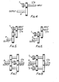
- the transmission unit shown in Figure 3 could be incorporated in any of the input, output or intermediate shafts in any of Figures 4 to 8, though it will be noted that on such transmission would be used for each of the intermediate shafts in the split train reduction gearing shown in Figure 8.
- the reversible transmissions described above with reference to the accompanying drawings permit adoption of a compact overall design possessing the high power transmission and permanently meshing characteristics of epicyclic gearing.
- the transmission is not restricted to marine usage and may be fitted into any gear system or into any transmission shaft wherever it suits the particular machinery arrangement, i.e. wherever a compact, high-power transmission is required. Because of its simplicity of design and small mass, it is operable in the minimum period of time.
- the reverse speed is usually arranged to be less than the forward speed, the sizes of the pinions 3 (103) which operate only in the star epicyclic configuration may be reduced accordingly, thus saving mass and permitting a more rapid response.
- the transmission may be further reduced in size and weight by incorporating load sharing arrangements into the planet pinion mountings.
- load sharing arrangements One practical way in which these loads can be shared more equally is to mount each planet pinion at one end of a resilient spindle, the other end of which is mounted on the carrier for the planet pinions.
- Such a construction is disclosed in U.K. Patent Specification No. 1,101,131.
- Such a load sharing arrangement comprises a resilient spindle which flexes under the effect of radial loads, the spindle being mounted between a gear wheel and a carrier on which the gear which is normally mounted. This resilience allows the gear wheel to be displaced bodily and laterally rather than being skewed and thus distributes the load equally between-a number of planet gears.
- Such a load sharing arrangement incorporated in the transmission hereinbefore described enables the load to be shared equally between the planet gears and thus permits the gears to be constructed so that they merely have to be capable of withstanding an average load and not so that they have to be constructed so as to be able to withstand the additional forces which result from normal manufacturing tolerances. This may enable the gears to be made smaller and may permit the manufacture of a more compact transmission, the transmission additionally having a smaller moment of inertia.
Landscapes
- Engineering & Computer Science (AREA)
- General Engineering & Computer Science (AREA)
- Mechanical Engineering (AREA)
- Chemical & Material Sciences (AREA)
- Combustion & Propulsion (AREA)
- Ocean & Marine Engineering (AREA)
- Retarders (AREA)
Applications Claiming Priority (2)
| Application Number | Priority Date | Filing Date | Title |
|---|---|---|---|
| GB3963077A GB1597475A (en) | 1977-09-22 | 1977-09-22 | Reversing gear transmissions |
| GB3963077 | 1978-05-24 |
Publications (1)
| Publication Number | Publication Date |
|---|---|
| EP0001348A1 true EP0001348A1 (de) | 1979-04-04 |
Family
ID=10410614
Family Applications (1)
| Application Number | Title | Priority Date | Filing Date |
|---|---|---|---|
| EP78300396A Withdrawn EP0001348A1 (de) | 1977-09-22 | 1978-09-18 | Zahnradgetriebe |
Country Status (2)
| Country | Link |
|---|---|
| EP (1) | EP0001348A1 (de) |
| GB (1) | GB1597475A (de) |
Cited By (5)
| Publication number | Priority date | Publication date | Assignee | Title |
|---|---|---|---|---|
| EP0007235A1 (de) * | 1978-07-17 | 1980-01-23 | Westinghouse Electric Corporation | Wendegetriebe |
| US4531429A (en) * | 1983-06-20 | 1985-07-30 | Westech Gear Corporation | Marine transmission |
| GB2169366A (en) * | 1985-01-04 | 1986-07-09 | Kidd Farm Machinery | Drive reversal mechanism |
| US4756211A (en) * | 1985-09-13 | 1988-07-12 | Fellows Thomas G | Continuously-variable ratio transmission for an automobile vehicle |
| EP1634758A1 (de) * | 2004-09-09 | 2006-03-15 | Comer Industries S.p.A. | Getriebeeinheit insbesondere für den Antrieb der Schraubenförderer und Hilfseinrichtungen von Mischwagen |
Citations (8)
| Publication number | Priority date | Publication date | Assignee | Title |
|---|---|---|---|---|
| DE343651C (de) * | ||||
| DE328862C (de) * | 1919-02-20 | 1920-11-05 | Luftfahrzeugbau Schuette Lanz | Planetenradwendegetriebe, insbesondere fuer Bootsmotoren |
| FR905503A (fr) * | 1944-02-15 | 1945-12-06 | Applic Des Brevets Cotal Soc D | Perfectionnements aux appareils de renversement de marche et de changement de vitesse applicables notamment aux bateaux |
| US2672769A (en) * | 1951-03-07 | 1954-03-23 | Le Roi Company | Transmission |
| GB989161A (en) * | 1963-05-13 | 1965-04-14 | Stal Laval Turbin Ab | Improvements in marine machinery |
| GB1004910A (en) * | 1962-12-21 | 1965-09-15 | Ass Elect Ind | Improvements in or relating to ship propulsion reverse gear transmission systems |
| DE1213688B (de) * | 1959-03-11 | 1966-03-31 | Daimler Benz Ag | Hydraulisch zu betaetigendes Planetenraeder-Wendegetriebe, insbesondere fuer Schiffsantriebe |
| GB1101131A (en) * | 1964-02-07 | 1968-01-31 | Nat Res Dev | Improvements relating to gears |
-
1977
- 1977-09-22 GB GB3963077A patent/GB1597475A/en not_active Expired
-
1978
- 1978-09-18 EP EP78300396A patent/EP0001348A1/de not_active Withdrawn
Patent Citations (8)
| Publication number | Priority date | Publication date | Assignee | Title |
|---|---|---|---|---|
| DE343651C (de) * | ||||
| DE328862C (de) * | 1919-02-20 | 1920-11-05 | Luftfahrzeugbau Schuette Lanz | Planetenradwendegetriebe, insbesondere fuer Bootsmotoren |
| FR905503A (fr) * | 1944-02-15 | 1945-12-06 | Applic Des Brevets Cotal Soc D | Perfectionnements aux appareils de renversement de marche et de changement de vitesse applicables notamment aux bateaux |
| US2672769A (en) * | 1951-03-07 | 1954-03-23 | Le Roi Company | Transmission |
| DE1213688B (de) * | 1959-03-11 | 1966-03-31 | Daimler Benz Ag | Hydraulisch zu betaetigendes Planetenraeder-Wendegetriebe, insbesondere fuer Schiffsantriebe |
| GB1004910A (en) * | 1962-12-21 | 1965-09-15 | Ass Elect Ind | Improvements in or relating to ship propulsion reverse gear transmission systems |
| GB989161A (en) * | 1963-05-13 | 1965-04-14 | Stal Laval Turbin Ab | Improvements in marine machinery |
| GB1101131A (en) * | 1964-02-07 | 1968-01-31 | Nat Res Dev | Improvements relating to gears |
Cited By (6)
| Publication number | Priority date | Publication date | Assignee | Title |
|---|---|---|---|---|
| EP0007235A1 (de) * | 1978-07-17 | 1980-01-23 | Westinghouse Electric Corporation | Wendegetriebe |
| US4531429A (en) * | 1983-06-20 | 1985-07-30 | Westech Gear Corporation | Marine transmission |
| GB2169366A (en) * | 1985-01-04 | 1986-07-09 | Kidd Farm Machinery | Drive reversal mechanism |
| US4756211A (en) * | 1985-09-13 | 1988-07-12 | Fellows Thomas G | Continuously-variable ratio transmission for an automobile vehicle |
| EP1634758A1 (de) * | 2004-09-09 | 2006-03-15 | Comer Industries S.p.A. | Getriebeeinheit insbesondere für den Antrieb der Schraubenförderer und Hilfseinrichtungen von Mischwagen |
| US7484437B2 (en) | 2004-09-09 | 2009-02-03 | Comer Industries S.P.A. | Transmission unit particularly for driving the screw feeders and auxiliary user devices of mixing trucks |
Also Published As
| Publication number | Publication date |
|---|---|
| GB1597475A (en) | 1981-09-09 |
Similar Documents
| Publication | Publication Date | Title |
|---|---|---|
| US3979972A (en) | Hydromechanical transmission | |
| US4693134A (en) | High-powered vehicle drive train | |
| US3470769A (en) | Input-split-power,output-split-power,compound-split-power,power train | |
| US5401221A (en) | Transmission of the toroidal-race, rolling-traction type having a mixer and a reducer epicyclic type gearing with clutches brakes | |
| EP1446594B1 (de) | Hydromechanisches, stufenloses getriebe | |
| US4334440A (en) | Automatic transmission | |
| US4802384A (en) | Procedure for shifting a transmission composed of several gear units | |
| US20090247346A1 (en) | Two speed planetary electric shift gearbox | |
| EP0400816A1 (de) | Getriebe | |
| US3465609A (en) | Transmission | |
| US3982448A (en) | Input-split hydromechanical transmission | |
| AU2002349206A2 (en) | Hydro-mechanical continuously variable transmission | |
| JPS6251800B2 (de) | ||
| US4353269A (en) | Ship's transmission with changeover from cruising speed to slow speed | |
| US3055233A (en) | Variable ratio transmission mechanism | |
| US4281564A (en) | Power train or transmission | |
| US3913411A (en) | Multispeed power transmission with plural countershafts | |
| US5509863A (en) | Transmission device, especially for boat motors | |
| US3209618A (en) | Transmission gear for motor vehicles | |
| EP0001348A1 (de) | Zahnradgetriebe | |
| US2592537A (en) | Power-transmitting system | |
| US3264902A (en) | Transmission | |
| US5259823A (en) | Transmissions | |
| US4074592A (en) | Direct drive transmission with hydraulically actuated forward and reverse clutches | |
| EP0007235A1 (de) | Wendegetriebe |
Legal Events
| Date | Code | Title | Description |
|---|---|---|---|
| PUAI | Public reference made under article 153(3) epc to a published international application that has entered the european phase |
Free format text: ORIGINAL CODE: 0009012 |
|
| AK | Designated contracting states |
Designated state(s): CH DE SE |
|
| 17P | Request for examination filed | ||
| STAA | Information on the status of an ep patent application or granted ep patent |
Free format text: STATUS: THE APPLICATION IS DEEMED TO BE WITHDRAWN |
|
| 18D | Application deemed to be withdrawn |
Effective date: 19850402 |
|
| RIN1 | Information on inventor provided before grant (corrected) |
Inventor name: CALVERLEY, JOHN |