EP1446594B1 - Hydromechanisches, stufenloses getriebe - Google Patents
Hydromechanisches, stufenloses getriebe Download PDFInfo
- Publication number
- EP1446594B1 EP1446594B1 EP02781000.1A EP02781000A EP1446594B1 EP 1446594 B1 EP1446594 B1 EP 1446594B1 EP 02781000 A EP02781000 A EP 02781000A EP 1446594 B1 EP1446594 B1 EP 1446594B1
- Authority
- EP
- European Patent Office
- Prior art keywords
- gear
- hydraulic
- output
- branch
- speed
- Prior art date
- Legal status (The legal status is an assumption and is not a legal conclusion. Google has not performed a legal analysis and makes no representation as to the accuracy of the status listed.)
- Expired - Lifetime
Links
Images




Classifications
-
- B—PERFORMING OPERATIONS; TRANSPORTING
- B62—LAND VEHICLES FOR TRAVELLING OTHERWISE THAN ON RAILS
- B62D—MOTOR VEHICLES; TRAILERS
- B62D11/00—Steering non-deflectable wheels; Steering endless tracks or the like
- B62D11/02—Steering non-deflectable wheels; Steering endless tracks or the like by differentially driving ground-engaging elements on opposite vehicle sides
- B62D11/06—Steering non-deflectable wheels; Steering endless tracks or the like by differentially driving ground-engaging elements on opposite vehicle sides by means of a single main power source
- B62D11/10—Steering non-deflectable wheels; Steering endless tracks or the like by differentially driving ground-engaging elements on opposite vehicle sides by means of a single main power source using gearings with differential power outputs on opposite sides, e.g. twin-differential or epicyclic gears
- B62D11/14—Steering non-deflectable wheels; Steering endless tracks or the like by differentially driving ground-engaging elements on opposite vehicle sides by means of a single main power source using gearings with differential power outputs on opposite sides, e.g. twin-differential or epicyclic gears differential power outputs being effected by additional power supply to one side, e.g. power originating from secondary power source
- B62D11/18—Steering non-deflectable wheels; Steering endless tracks or the like by differentially driving ground-engaging elements on opposite vehicle sides by means of a single main power source using gearings with differential power outputs on opposite sides, e.g. twin-differential or epicyclic gears differential power outputs being effected by additional power supply to one side, e.g. power originating from secondary power source the additional power supply being supplied hydraulically
-
- F—MECHANICAL ENGINEERING; LIGHTING; HEATING; WEAPONS; BLASTING
- F16—ENGINEERING ELEMENTS AND UNITS; GENERAL MEASURES FOR PRODUCING AND MAINTAINING EFFECTIVE FUNCTIONING OF MACHINES OR INSTALLATIONS; THERMAL INSULATION IN GENERAL
- F16H—GEARING
- F16H47/00—Combinations of mechanical gearing with fluid clutches or fluid gearing
- F16H47/02—Combinations of mechanical gearing with fluid clutches or fluid gearing the fluid gearing being of the volumetric type
- F16H47/04—Combinations of mechanical gearing with fluid clutches or fluid gearing the fluid gearing being of the volumetric type the mechanical gearing being of the type with members having orbital motion
-
- F—MECHANICAL ENGINEERING; LIGHTING; HEATING; WEAPONS; BLASTING
- F16—ENGINEERING ELEMENTS AND UNITS; GENERAL MEASURES FOR PRODUCING AND MAINTAINING EFFECTIVE FUNCTIONING OF MACHINES OR INSTALLATIONS; THERMAL INSULATION IN GENERAL
- F16H—GEARING
- F16H37/00—Combinations of mechanical gearings, not provided for in groups F16H1/00 - F16H35/00
- F16H37/02—Combinations of mechanical gearings, not provided for in groups F16H1/00 - F16H35/00 comprising essentially only toothed or friction gearings
- F16H37/06—Combinations of mechanical gearings, not provided for in groups F16H1/00 - F16H35/00 comprising essentially only toothed or friction gearings with a plurality of driving or driven shafts; with arrangements for dividing torque between two or more intermediate shafts
- F16H37/08—Combinations of mechanical gearings, not provided for in groups F16H1/00 - F16H35/00 comprising essentially only toothed or friction gearings with a plurality of driving or driven shafts; with arrangements for dividing torque between two or more intermediate shafts with differential gearing
- F16H37/0833—Combinations of mechanical gearings, not provided for in groups F16H1/00 - F16H35/00 comprising essentially only toothed or friction gearings with a plurality of driving or driven shafts; with arrangements for dividing torque between two or more intermediate shafts with differential gearing with arrangements for dividing torque between two or more intermediate shafts, i.e. with two or more internal power paths
- F16H37/084—Combinations of mechanical gearings, not provided for in groups F16H1/00 - F16H35/00 comprising essentially only toothed or friction gearings with a plurality of driving or driven shafts; with arrangements for dividing torque between two or more intermediate shafts with differential gearing with arrangements for dividing torque between two or more intermediate shafts, i.e. with two or more internal power paths at least one power path being a continuously variable transmission, i.e. CVT
- F16H2037/088—Power-split transmissions with summing differentials, with the input of the CVT connected or connectable to the input shaft
-
- F—MECHANICAL ENGINEERING; LIGHTING; HEATING; WEAPONS; BLASTING
- F16—ENGINEERING ELEMENTS AND UNITS; GENERAL MEASURES FOR PRODUCING AND MAINTAINING EFFECTIVE FUNCTIONING OF MACHINES OR INSTALLATIONS; THERMAL INSULATION IN GENERAL
- F16H—GEARING
- F16H47/00—Combinations of mechanical gearing with fluid clutches or fluid gearing
- F16H47/02—Combinations of mechanical gearing with fluid clutches or fluid gearing the fluid gearing being of the volumetric type
- F16H47/04—Combinations of mechanical gearing with fluid clutches or fluid gearing the fluid gearing being of the volumetric type the mechanical gearing being of the type with members having orbital motion
- F16H2047/045—Combinations of mechanical gearing with fluid clutches or fluid gearing the fluid gearing being of the volumetric type the mechanical gearing being of the type with members having orbital motion the fluid gearing comprising a plurality of pumps or motors
Definitions
- This invention relates to a drive system useful as a vehicle propulsion system or stationary equipment drive, combining mechanical and hydraulic power systems.
- Hydraulic drive systems are commonly used for large vehicles or stationary equipment. However, as the output speed increases at a given gear setting, the efficiency of the hydraulic drive is correspondingly reduced. This makes it inefficient to run hydraulic drives at the upper half of the gear setting. This problem may be overcome by having multiple gear settings, but the complexity of the resulting transmission negates the benefits of using a hydraulic drive.
- An alternative to a hydraulic drive system is a mechanically driven system.
- conventional mechanical drive systems are limited to discrete gear ratios, which do not allow for infinite speed ratios as found in hydraulic drives.
- a great deal of power management between the engine and the transmission at all output speeds is necessary for transmission effectiveness.
- a purely mechanical drive is inadequate to ensure the efficient use of the engine's available power due to the discrete speed ratios, while a purely hydraulic drive has inherently poor efficiency at higher operational speeds.
- the invention comprises a hydro-mechanical continuously variable transmission (HMCVT) that uses a planetary gear system to provide a combination of hydraulic and mechanical power for a vehicle or stationary equipment.
- HMCVT hydro-mechanical continuously variable transmission
- the HMCVT may also include a 2-speed planetary clutch system to expand the operating parameters of the vehicle or stationary equipment.
- the HMCVT may further include a planetary steering system that works with or without the 2-speed planetary clutch system.
- the HMCVT may also include a launch assist device to limit torque applied to the drive pump when the ratio of hydraulic pump displacement to hydraulic motor displacement is small.
- the HMCVT may additionally include a lockup brake coupled to the hydraulic branch input, operative to lock out the hydraulic branch and force all power through the mechanical branch when the transmission output is operating at a pre-selected percentage of its maximum speed.
- the lockup brake may be combined with the launch assist device into a single device.
- the HMCVT may further include an anti-recirculating reverser device operative to allow the transmission output to operate in a reverse direction of motion without developing a recirculating power flow through the mechanical branch.
- the 2-speed planetary clutch, planetary steering system, launch assist device, lockup brake and anti-recirculating reverser device may be used individually or in any combination of two or more in any given HMCVT.
- the hydro-mechanical continuously variable transmission is designed to split input power between a hydraulic drive branch, using a hydraulic pump and motor, and a parallel mechanical drive branch, using shafts and/or gears, recombining the power from each branch into a single output.
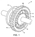
- the HMCVT is based on a planetary gear set 10 as shown in Figure 1 .
- a planetary gear set 10 consists of four parts: a carrier 12, a number of planetary gears 14, an internal ring gear 15 and a sun gear 18.
- the ring gear 15 and the sun gear 18 are connected through the planetary gears 14.
- the planetary gears 14 are also connected to the carrier gear 12.
- three planetary gears 14a-c are used, more may be used if necessary.
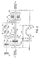
- the planetary gear set 10 is connected to the hydraulic drive pump 22 through transfer gear 13 and transfer gear 16,(see Figure 2 ).
- the planetary gear set is also connected to the main shaft 26 and the transmission input 40.
- FIG. 2 A full HMCVT system in a RSC configuration with all optional components connected is shown in Figure 2 .
- input power is transferred to a variable displacement hydraulic drive pump 22 by means of transfer gears 16 and 13.
- Sun gear 18 is connected to the combiner gear 20, i.e. transfer gear, via the main shaft 26 and transfer gear 19.
- the combiner gear 20 is also connected to a variable hydraulic drive motor 24.
- the input 40 from the main engine (not shown) to the HMCVT is received by the carrier gear 12.
- Additional elements of the invention include lock up brake 80, 2-speed output shaft 36, launch assist device 70, high-speed clutch 34, low speed clutch or brake 32, a 2-speed shifting planetary gear set 30, two steering planetary gear sets 52a, 52b, a steering system pump 54, a steering system motor 56, and a zero shaft 58.
- FIG. 4 A full HMCVT system in a SCR configuration is shown in Figure 4 (not itself constituting an embodiment of the invention).
- a hydraulic drive pump 22 is connected to the sun gear 18 of the planetary gear set 10 and the carrier 12 is connected to the combiner gear 20 via the main shaft 26 and transfer gear 19.
- the combiner gear 20 is also connected to a hydraulic drive motor 24.
- the input 40 to the HMCVT is received by the ring gear 15.
- FIG. 5 A full HMCVT system in a SRC configuration is shown in Figure 5 (not itself constituting an embodiment of the invention).
- a hydraulic drive pump 22 is connected to the sun gear 18 of the planetary gear set 10
- Ring gear 15 is connected to the combiner gear 20 via the main shaft 26 and transfer gear 19.
- the combiner gear 20 is also connected to a hydraulic drive motor 24.
- the input 40 to the HMCVT is received by the carrier 12.
- any of the carrier gear 12, ring gear 15 and sun gear 18 may be connected to the input 40, drive pump 22 and main shaft 26 in any combination.
- the above three configurations have tested as the most practical for application as transmissions for large vehicles.
- the power is split such that the power from the hydraulic system (including the drive pump 22 and the drive motor 24 ) combines with the mechanical system (including the main shaft 26 ) to equal 100% of the total power less efficiency losses. It can further be shown that the percentage of mechanical power increases as the output speed increases, with a corresponding decrease in hydraulic power. The result is a more efficient use of the input energy 40 than in a strictly hydraulic or strictly mechanical transmission.
- the torque ratio between the ring gear 15 and the sun gear 18 is only dependent on the gear ratio between the ring gear 15 and the sun gear 18. This means that the final gear ratio of the HMCVT can be set by the choice of ring gear 15 and sun gear 18.
- O h 0.
- O m RS, where S reflects the actual speed of the output (as a value from 0 to 1). R and S are used to make the equations independent of the actual configuration of the planetary gear set 10.
- the combiner gear 20 ( Figure 2 .) and planetary gear set 10 are responsible for controlling the distribution of power between the hydraulic and mechanical systems.
- the power split between the hydraulic and mechanical systems is changed as described above.
- main shaft 26 is also motionless (0 rpm).
- the drive pump 22 must pump fluid and, initially, all the power is derived from the drive pump 22 and drive motor 24.
- the main shaft 26 and the connected drive motor 24 (through the combiner gear 20 ) must turn faster.
- the drive pump gear (in the RSC configuration, ring gear 15 ) turns slower, due to the effect of the planetary gear system 10 and the need to maintain a constant torque ratio.
- the drive pump gear (in the RSC configuration, ring gear 15 ) turns slower, due to the effect of the planetary gear system 10 and the need to maintain a constant torque ratio.
- HMCVT lies in the unique ability of the configured systems as shown in Figures 2-5 to enable a driven output on both ends of the transmission via a common shaft 26. This is particularly useful in vehicles or stationary equipment that require duplicated output shafts to two drives such as tracks and/or differentials.
- one or both of the outputs can be engaged or disengaged eliminating the need for a transfer case when configured for multiple output drives.
- the HMCVT speed can be controlled in any conventional manner, however an electronic control system is preferred to best optimize the power splitting in connection with the output speed.
- the electronic control system can also include control means for the two-speed transmission system, planetary steering system, launch assist device, lockup brake and anti-recirculatory reverser discussed below.
- An additional modification to optimize the use of the HMCVT is a two-speed planetary clutch system as shown in Figure 6 .
- the main shaft 26 is connected to the input of an additional 2-speed shifting planetary 30.
- Power enters the shifting planetary through the shifting planetary sun gear 31 and exits through the shifting planetary carrier 35 and 2-speed output shaft 36, as shown in Figure 6 .
- the shifting planetary ring gear 33 is held fixed by a low-speed clutch or brake 32. creating a reduction in the gear ratio. Shifting to high gear for high-speed operation is accomplished by releasing the brake 32 and applying a high-speed clutch 34 to effectively give a 1:1 gear ratio.
- the 2-speed planetary clutch system provides an extended range of available speeds and torques to the operator. The result is an increased operating envelope for the vehicle or stationary equipment.
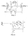
- FIG. 2 and 7 Another useful modification for the HMCVT is a planetary steering system as shown in Figures 2 and 7 (the arrangement of Figure 7 not itself constituting an embodiment of the invention).
- power is sent from the main input 40 to two steering planetary gear sets 52a and 52b, one for each output drive on either side of the transmission. If a two speed is also to be incorporated as shown in Figure 2 , power is sent from the 2-speed output shaft to steering planetary gear sets 52a and 52b.
- the steering system also includes a closed-loop hydraulic pump 54 that is driven in relation to the current engine RPM.
- the output of the pump 54 is connected to a hydraulic motor 56 that drives a cross shaft assembly referred to as a zero shaft 58.
- the zero shaft 58 is connected to the sun gear 60 of the left and right steering planetary gear sets 52a and 52b, and the left and right sun gears 60 are driven by the motor 56 in opposite directions. Therefore, when the zero shaft 58 turns, the speed of the inside drive of the vehicle decreases and the speed of the outside drive increases.
- the result of the planetary steering system is a high-precision steering system that provides quick reaction times while maintaining good driving characteristics during straight-ahead motion.
- LAD Launch Assist Device
- HMCVT One characteristic of the HMCVT is that at low output speeds, the pump 22 is set to a very low displacement and the motor 24 is set to a high displacement. In theory, this could create a very large torque multiplication through the hydraulic branch of the HMCVT. However, in that scenario, the hydraulic pressures generated would exceed those that can be withstood by the system. Therefore, the hydraulic ratio must be reduced to limit pressure to acceptable levels. Unfortunately, this corrective measure also reduces the output torque at very low speeds.
- LAD 70 an energy absorber, called a Launch Assist Device (LAD) 70 is attached to the pump 22 as shown in Figure 8 (not itself constituting an embodiment of the invention).
- the LAD 70 provides an initial resistance to the gear element of the planetary 10 driving the hydraulic branch. This resistance limits the torque available to the pump 22 and allows the mechanical branch to reach its full torque output at very low speeds. As a result, the torque is available at the output of the HMCVT.
- the LAD 70 is only required at very low speeds and should be gradually phased out as the speed increases. As shown, the LAD 70 is a modulated brake assembly. However, other devices, including hydroynamic devices such as a fluid coupling or a torque converter, could be used.
- the displacement ratio between the motor 24 and the pump 22 decreases to the point where the amount of torque available to the pump 22 is insufficient to keep it turning. With the speed of the hydraulic pump 22 at zero, all the power is transferred exclusively through the mechanical branch. Unfortunately, most currently available pump and motor designs include some degree of internal leakage, preventing the HMCVT from reaching a pure 100% mechanical state.
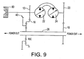
- a lockup brake 80 as shown in Figure 9 (not itself constituting an embodiment of the invention) to prevent the pump 22 from turning at the end of the operating range.
- the lockup brake 80 is attached to one of the gears 10 driving the pump 22.
- the lockup brake 80 is activated, forcing the HMCVT into a pure 100% mechanical mode.
- the lockup brake 80 can then be deactivated when the HMCVT operating range falls out of the upper regions.
- the activation/deactivation point for the lockup brake 80 will be determined by the operating conditions and parameters for the vehicle or stationary equipment using the HMCVT.
- the simplest way to reverse the direction of the final output of the transmission is to reverse the drive motor.
- the power in the mechanical branch is negative and the power in the hydraulic branch is greater than the input power.
- the drive motor must reverse the direction of the mechanical output of the split speed, feeding power upstream through the mechanical branch.
- the hydraulic branch must transfer an amount of power equal to the input plus the recirculated power from the mechanical branch.
- both the hydraulic and the mechanical branches must have increased component strength and/or size, which is not always practical or desirable. Therefore, an additional reverser subsystem that avoids the need to reinforce the hydraulic is desirable.
- Two potential reverser subsystems 90, 100 as shown in Figures 10 and 11 respectively involve the installation of a reversible gear at the input.
- input 40 is connected through one of the two gear sets 97, 98 to a sliding clutch/synchronizer assembly 91.
- the HMCVT components including the drive pump 22 and motor 24, will rotate in either the forward or reverse direction.
- Either spur gears 97 , 98 ( FIG. 10 ) or bevel gears 101a, 101b, 101c ( FIG.11 ) can be used in clutch/synchronizers 91, 92; however, bevel gears allow for a 90-degree change between the engine power output and the main axes of the transmission (the final power output).
- steering planetary gear sets 52a and 52b are present, they are connected to the power output through a preset gear ratio and a constant direction so that the steering will function regardless of the forward/reverse direction of clutch/synchronizers 100 and 90.
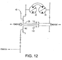
- An alternative subsystem for the reverser shown in Figure 12 disconnects the mechanical branch during reverse hydraulic operation and locks the mechanical output to the transmission housing (not shown).
- the mechanical output may be selectively coupled to either the main shaft 26 or the transmission housing by means of a clutch/synchronizer assembly 112.
- the mechanical output When the mechanical output is connected to the main shaft 26, forward output speeds result.
- the mechanical branch When the mechanical output is connected to the housing, the mechanical branch is locked out of the transmission. Reverse output speeds can then be achieved by reversing the direction of the drive motor. Power flows exclusively through the hydraulic branch and cannot be recirculated back through the mechanical branch.
Landscapes
- Engineering & Computer Science (AREA)
- General Engineering & Computer Science (AREA)
- Mechanical Engineering (AREA)
- Chemical & Material Sciences (AREA)
- Combustion & Propulsion (AREA)
- Transportation (AREA)
- Structure Of Transmissions (AREA)
- Non-Deflectable Wheels, Steering Of Trailers, Or Other Steering (AREA)
Claims (8)
- Ein hydromechanisches stufenloses Getriebe des Typs, der über Folgendes verfügt:a. einen Getriebeeingang (40);b. eine Hauptwelle (26);c. einen ersten Planetengetriebesatz (10), umfassend:i) ein erstes Hohlrad (15), ii) ein erstes Sonnenrad (18), und iii) ein erstes Zwischenrad (12);d. ein erstes Verteilergetriebe (13);e. ein zweites Verteilergetriebe (16);f. ein drittes Verteilergetriebe (19);g. ein viertes Verteilergetriebe (20);h. einen Hydraulikzweig, umfassend:i) eine erste Hydraulikpumpe (22), gekuppelt an den genannten Getriebeeingang (40) durch das genannte erste Verteilergetriebe (13) und das genannte zweite Verteilergetriebe (16), sowieii) einen ersten Hydraulikmotor (24), gekuppelt an die genannte erste Hydraulikpumpe (22), wobei ein Ausgang des genannten Hydraulikzweigs über das genannte vierte Verteilergetriebe (20) und das genannte dritte Verteilergetriebe (19) auf die genannte Hauptwelle (26) übertragen wird,j. einen mechanischen Zweig, umfassend die genannte Hauptwelle (26), wobei der genannte mechanische Zweig an den genannten Getriebeeingang (40) und an das genannte dritte Verteilergetriebe (19) gekuppelt ist,
wobei der genannte Getriebeeingang (40) an eines des genannten ersten Hohlrads (15), des genannten ersten Sonnenrads (18) und des genannten ersten Zwischenrads (12) gekuppelt ist, und
wobei der genannte Hydraulikzweig an ein zweites des genannten ersten Hohlrads (15), des genannten ersten Sonnenrads (18) und des genannten ersten Zwischenrads (12) gekuppelt ist, und
wobei der genannte mechanische Zweig an ein drittes des genannten ersten Hohlrads (15), des genannten ersten Sonnenrads (18) und des genannten ersten Zwischenrads (12) gekuppelt ist, und
wobei der Ausgang des genannten Hydraulikzweigs und der Ausgang des genannten mechanischen Zweigs an dem genannten dritten Verteilergetriebe (19) und dem genannten vierten Verteilergetriebe (20) so zusammengeführt sind, dass ein Prozentsatz der aus dem genannten Hydraulikzweig entstehenden Leistung mit zunehmender Drehzahl der genannten Hauptwelle (26) abnimmt, und
wobei das genannte hydromechanische stufenlose Getriebe gekennzeichnet ist, dass es außerdem Folgendes umfasst:k. einen Zweigang-Planetenschaltgetriebesatz (30), umfassend ein zweites Sonnenrad (31), ein zweites Hohlrad (33) und ein zweites Zwischenrad (35), wobei der Zweigang-Planetenschaltgetriebesatz (30) die am dritten Verteilergetriebe (19) und am vierten Verteilergetriebe (20) zusammengeführte Leistung an eine Abtriebswelle (36) überträgt;l. eine Langsamlaufkupplung oder Bremse (32), undm. eine Hochgeschwindigkeitskupplung (34),
wobei die genannte Langsamlaufkupplung oder Bremse (32) betriebsfähig ist, um das zweite Hohlrad (33) für den Betrieb bei niedriger Drehzahl zu fixieren, und
wobei der genannte Zweigang-Planetenschaltgetriebesatz (30) und die genannte Hochgeschwindigkeitskupplung (34) wirksam sind, um für den Betrieb bei hoher Drehzahl ein Übersetzungsverhältnis von 1:1 herzustellen. - Hydromechanisches stufenloses Getriebe nach Anspruch 1, ferner dadurch gekennzeichnet, dass:a) die genannte Hauptwelle (26) an das genannte zweite Sonnenrad (31) gekuppelt ist, undb) das genannte zweite Zwischenrad (35) an die genannte Abtriebswelle (36) gekuppelt ist.
- Hydromechanisches stufenloses Getriebe nach Anspruch 1, gekennzeichnet als ferner umfassend eine Anfahrhilfevorrichtung, um das bei niedriger Ausgangsdrehzahl an den hydraulischen Zweig angelegte Drehmoment zu begrenzen, wobei die genannte Anfahrhilfevorrichtung einen an die genannte erste Hydraulikpumpe (22) gekuppelten Energie-Absorber (70) umfasst, um dem Hydraulikzweig-Eingang Widerstand zu leisten, sowie eine Regelvorrichtung, um die Menge der Energieabsorption zu regeln.
- Hydromechanisches stufenloses Getriebe nach Anspruch 1, gekennzeichnet als ferner umfassend eine Sperrbremse (80), gekuppelt an die genannte erste Hydraulikpumpe (22), wobei die genannte Sperrbremse (80) betriebsfähig ist, um den genannten hydraulischen Zweig auszusperren und die gesamte Leistung durch den genannten mechanischen Zweig zu zwingen, wenn die genannte Hauptwelle (26) mit einem vorgewählten Prozentsatz ihrer Höchstdrehzahl läuft.
- Hydromechanisches stufenloses Getriebe nach Anspruch 1, gekennzeichnet als ferner umfassend eine rückführungshemmende Umkehrvorrichtung (90), betriebsfähig, um der genannten Hauptwelle (26) den Betrieb in einer umgekehrten Bewegungsrichtung zu erlauben, ohne einen rückfließenden Leistungsfluss zu einer vorgeschalteten Stufe durch den genannten mechanischen Zweig zu entwickeln.
- Hydromechanisches stufenloses Getriebe nach Anspruch 5, wobei die genannte rückführungshemmende Umkehrvorrichtung (90) eine(n) Kupplung/Synchronisator (112) umfasst, wobei die/der genannte Kupplung/Synchronisator an den Ausgang des mechanischen Zweigs gekuppelt ist, und
wobei die/der genannte Kupplung/Synchronisator (112) betriebsfähig ist, um in die genannte Abtriebswelle (36) gezielt für den Ausgangsbetrieb in Vorwärtsrichtung einzugreifen, und
wobei die/der genannte Kupplung/Synchronisator (112) betriebsfähig ist, um in ein Gehäuse des genannten Getriebes gezielt für den Ausgangsbetrieb in rückwärtiger Richtung einzugreifen, und
wobei die/der genannte Kupplung/Synchronisator (112) betriebsfähig ist, für den Ausgangsbetrieb im Leerlauf in nichts einzugreifen,
wobei, im Ausgangsbetrieb in rückwärtiger Richtung der mechanische Ausgang am Drehen gehindert wird und Leistung lediglich durch den genannten Hydraulikzweig fließt. - Hydromechanisches stufenloses Getriebe nach Anspruch 5, wobei die genannte rückführungshemmende Umkehrvorrichtung (90) eine(n) an den genannten Getriebeeingang (40) gekuppelte(n) Kupplung/Synchronisator (91) umfasst, wobei die/der genannte Kupplung/Synchronisator (91) mit zwei koaxial an beiden Seiten der genannten Kupplung/des genannten Synchronisators befindlichen Zahnradsätzen (97, 98) ausgestattet ist, und wobei jeder der genannten Zahnradsätze ein Zahnradgetriebe von gleicher und entgegengesetzter Getriebeübersetzung antreibt, und wobei das Zahnradgetriebe an eines des genannten ersten Hohlrades (15), des genannten ersten Sonnenrades (18) und des genannten ersten Zwischenrades (12) gekuppelt ist, und wobei die Drehung der genannten Hauptabtriebswelle (26) in Vorwärtsrichtung, im Leerlauf oder in rückwärtiger Richtung dadurch bestimmt wird, dass die/der genannte Kupplung/Synchronisator (112) in einen der genannten zwei Zahnradsätze (97, 98) bzw. in den anderen der genannten zwei Zahnradsätze oder in keinen der genannten zwei Zahnradsätze eingreift.
- Hydromechanisches stufenloses Getriebe nach Anspruch 1, gekennzeichnet als ferner umfassend ein planetares Lenksystem, umfassend:a. eine zweite Hydraulikpumpe (54);b. einen zweiten Hydraulikmotor (56);c. eine Nullwelle (58), wobei die genannte Nullwelle (58) von dem genannten zweiten Hydraulikmotor (56) angetrieben wird, und wobei die genannte Nullwelle (58) Ausgänge umfasst, so verzahnt, dass sie sich mit gleicher Drehzahl, jedoch in entgegengesetzte Richtungen drehen, undd. zwei Lenkungs-Planetengetriebesätze (52) mit identischen Übersetzungsverhältnissen, wobei die genannten Lenkungs-Planetengetriebesätze (52) an der genannten Hauptwelle (26) koaxial ausgerichtet sind,wobei ein Eingang eines jeden der genannten zwei Planetengetriebesätze (52) an einen der Ausgänge der genannten Nullwelle (58) gekuppelt ist;
und wobei ein zweiter Eingang eines jeden Lenkungs-Planetengetriebesatzes (52) an die genannte Hauptwelle (26) gekuppelt ist;
und wobei ein Ausgang eines jeden der genannten zwei Lenkungs-Planetengetriebesätze (52) auf einander gegenüberliegende Seiten des genannten hydromechanischen stufenlosen Getriebes gerichtet ist;
und wobei die genannte zweite Hydraulikpumpe (54) und der genannte zweite Hydraulikmotor (56) betriebsfähig sind, um die Höhe der der genannten Nullwelle (58) zur Verfügung stehenden Leistung zu steuern.
Applications Claiming Priority (3)
| Application Number | Priority Date | Filing Date | Title |
|---|---|---|---|
| CA002363653A CA2363653A1 (en) | 2001-11-22 | 2001-11-22 | Hydro-mechanical continuously variable transmission |
| CA2363653 | 2001-11-22 | ||
| PCT/CA2002/001789 WO2003046415A1 (en) | 2001-11-22 | 2002-11-19 | Hydro-mechanical continuously variable transmission |
Publications (2)
| Publication Number | Publication Date |
|---|---|
| EP1446594A1 EP1446594A1 (de) | 2004-08-18 |
| EP1446594B1 true EP1446594B1 (de) | 2016-10-19 |
Family
ID=4170633
Family Applications (1)
| Application Number | Title | Priority Date | Filing Date |
|---|---|---|---|
| EP02781000.1A Expired - Lifetime EP1446594B1 (de) | 2001-11-22 | 2002-11-19 | Hydromechanisches, stufenloses getriebe |
Country Status (8)
| Country | Link |
|---|---|
| US (1) | US7357744B2 (de) |
| EP (1) | EP1446594B1 (de) |
| JP (1) | JP2005510678A (de) |
| KR (1) | KR100936831B1 (de) |
| CN (1) | CN100436880C (de) |
| AU (1) | AU2002349206B2 (de) |
| CA (1) | CA2363653A1 (de) |
| WO (1) | WO2003046415A1 (de) |
Families Citing this family (30)
| Publication number | Priority date | Publication date | Assignee | Title |
|---|---|---|---|---|
| WO2008015549A2 (en) * | 2006-08-03 | 2008-02-07 | Toyota Jidosha Kabushiki Kaisha | Power split dual input shaft transmission for vehicle |
| US7824308B2 (en) * | 2007-09-06 | 2010-11-02 | Eaton Corporation | Methods for shifting a vehicle transmission |
| US8308597B2 (en) * | 2007-09-20 | 2012-11-13 | Kubota Corporation | Speed change transmission system |
| US8424633B2 (en) * | 2007-10-02 | 2013-04-23 | Zf Friedrichshafen Ag | Variable transmission device for a vehicle |
| US7789795B2 (en) * | 2007-10-17 | 2010-09-07 | Eaton Corporation | Method for controlling a vehicle powertrain having step ratio gearing and a continuously variable transmission to achieve optimum engine fuel economy |
| WO2010144753A1 (en) * | 2009-06-10 | 2010-12-16 | Czero, Inc. | Systems and methods for hybridization of a motor vehicle using hydraulic components |
| US20150018153A1 (en) * | 2011-06-21 | 2015-01-15 | Volvo Construction Equipment Ab | Method for controlling a power split continuously variable transmission and a power split continuously variable transmission |
| DE102011082672A1 (de) * | 2011-09-14 | 2013-03-14 | Zf Friedrichshafen Ag | Getriebevorrichtung mit wenigstens einem Variator zum stufenlosen Variieren einer Übersetzung und mit primärer Leistungsverzweigung |
| DE102012216277B4 (de) * | 2012-09-13 | 2022-07-14 | Zf Friedrichshafen Ag | Getriebevorrichtung mit einer Planetengetriebeeinrichtung |
| DE102013110463A1 (de) * | 2012-12-17 | 2014-06-18 | Linde Hydraulics Gmbh & Co. Kg | Leistungsverzweigungsgetriebe eines Fahrantrieb eines Fahrzeugs |
| GB201223536D0 (en) | 2012-12-21 | 2013-02-13 | Agco Int Gmbh | Agricultural vehicle transmission |
| KR101654232B1 (ko) | 2013-06-04 | 2016-09-06 | 삼성디스플레이 주식회사 | 유기 발광 표시 장치 및 이의 제조 방법 |
| EP3047176A4 (de) * | 2013-09-17 | 2017-06-28 | Kinetics Drive Solutions Inc. | Getriebe mit stromabzweigung und einem mehrgängigen kombinierer |
| US20170261084A1 (en) * | 2014-10-24 | 2017-09-14 | Robert Hugh Francis Lloyd | Enhancements to hydro-mechanical vehicle transmission using fixed-displacement pump/motors |
| US10093302B2 (en) | 2015-12-08 | 2018-10-09 | Caterpillar Inc. | Supplemental hydraulic motor for continuously variable transmission |
| CN106949221A (zh) * | 2016-01-07 | 2017-07-14 | 熵零技术逻辑工程院集团股份有限公司 | 一种传动机构 |
| US10077828B2 (en) | 2016-04-18 | 2018-09-18 | Caterpillar Inc. | Powertrain system for machine and method of operating same |
| DE102016212209A1 (de) * | 2016-07-05 | 2018-01-11 | Zf Friedrichshafen Ag | Nebenabtriebsanordnung |
| US10384714B2 (en) * | 2016-12-16 | 2019-08-20 | Allison Transmission, Inc. | Direct drive pivot and pivot lockup of a transmission system and method thereof |
| CN106818061B (zh) * | 2017-02-15 | 2019-03-05 | 苏州萨伯工业设计有限公司 | 液控比例转向方法 |
| KR101867529B1 (ko) | 2017-11-21 | 2018-06-14 | 황종원 | 피스톤 펌프 |
| US10731735B1 (en) * | 2018-03-19 | 2020-08-04 | Mainstream Engineering Corporation | Power transfer system and method using a variable speed ratio regulating device |
| CN108980298B (zh) * | 2018-07-19 | 2021-06-08 | 中国北方车辆研究所 | 液压液力机械复合多功率流传动装置 |
| US11098792B2 (en) | 2019-09-30 | 2021-08-24 | Caterpillar Inc. | Transmission system for machine |
| CN111207198B (zh) * | 2020-01-20 | 2021-06-18 | 江苏大学 | 一种集齿轮-液压-金属带为一体的多模式机液复合传动装置 |
| CN112622599B (zh) * | 2020-12-28 | 2022-06-28 | 潍柴动力股份有限公司 | 一种机械-液压传动系统、其模式切换控制方法及工程机械 |
| CN113187892B (zh) * | 2021-05-24 | 2022-08-23 | 潍柴动力股份有限公司 | 一种保护拖拉机变速箱的方法及装置 |
| US11493119B1 (en) | 2021-08-24 | 2022-11-08 | Dana Italia S.R.L. | Hydromechanical transmission and control method |
| US11480238B1 (en) | 2021-08-24 | 2022-10-25 | Dana Italia S.R.L. | Hydromechanical transmission and control method |
| CN115056648B (zh) * | 2022-07-06 | 2024-07-19 | 潍柴动力股份有限公司 | 传动系统及具有其的车辆 |
Citations (5)
| Publication number | Priority date | Publication date | Assignee | Title |
|---|---|---|---|---|
| US3396610A (en) * | 1966-03-24 | 1968-08-13 | Borg Warner | Transmission mechanism |
| US3979973A (en) * | 1970-12-08 | 1976-09-14 | Hermann Klaue | Starting device for heavy vehicles |
| EP0423863A1 (de) * | 1989-10-19 | 1991-04-24 | Saab-Scania Aktiebolag | Planetengetriebe mit Synchronisiereinrichtung |
| WO1992001173A1 (de) * | 1990-07-03 | 1992-01-23 | Zahnradfabrik Friedrichshafen Ag | Bereichsgetriebe für kraftfahrzeuge |
| WO2001086172A1 (en) * | 2000-04-03 | 2001-11-15 | Volvo Lastvagnar Ab | Range gearbox |
Family Cites Families (24)
| Publication number | Priority date | Publication date | Assignee | Title |
|---|---|---|---|---|
| DE1158380B (de) | 1961-09-14 | 1963-11-28 | Daimler Benz Ag | Hydrostatischer Antrieb fuer Fahrzeuge, insbesondere fuer Kraftfahrzeuge |
| US3446093A (en) * | 1967-05-19 | 1969-05-27 | Urs Corp | Split-torque hydromechanical transmission |
| US3426621A (en) * | 1968-02-23 | 1969-02-11 | Gen Motors Corp | Power train |
| US3492891A (en) * | 1968-07-03 | 1970-02-03 | Gen Motors Corp | Single speed range input-split-power drive,multispeed range compound-split-power drive,power train |
| US3575006A (en) * | 1968-09-20 | 1971-04-13 | Tel E Elect Inc | Underground cable-laying apparatus |
| US3534635A (en) * | 1968-11-27 | 1970-10-20 | Gen Motors Corp | Power train |
| DE2405804A1 (de) | 1973-02-10 | 1974-08-15 | Serck Industries Ltd | Hydrostatisches getriebe |
| DE2335629C3 (de) | 1973-07-13 | 1978-05-18 | Xaver Fendt & Co, 8952 Marktoberdorf | Hydrostatisch-mechanischer Antrieb fur land- und bauwirtschaftlich genutzte Fahrzeuge |
| US3897697A (en) * | 1974-02-01 | 1975-08-05 | Caterpillar Tractor Co | Infinitely variable drive ratio hydro-mechanical transmission for vehicles or the like |
| US3982448A (en) * | 1975-03-27 | 1976-09-28 | General Motors Corporation | Input-split hydromechanical transmission |
| US4122732A (en) * | 1977-01-17 | 1978-10-31 | General Motors Corporation | Hydromechanical mechanical continuously variable transmission |
| DE3475059D1 (en) * | 1983-08-25 | 1988-12-15 | Torotrak Dev Ltd | Driveline for a track-laying vehicle |
| JPS59187140A (ja) * | 1983-12-23 | 1984-10-24 | Komatsu Ltd | 装軌車両の変速・操向装置 |
| JPS60227045A (ja) * | 1984-04-25 | 1985-11-12 | Mitsubishi Heavy Ind Ltd | 変速操向装置 |
| CN1005788B (zh) * | 1985-10-08 | 1989-11-15 | 株式会社岛津制作所 | 液力机械式变速器 |
| DE3641648A1 (de) * | 1986-12-05 | 1988-06-16 | Michael Meyerle | Stufenloses fahr- und lenkgetriebe fuer gleiskettenfahrzeuge |
| JPH0266361A (ja) * | 1988-08-31 | 1990-03-06 | Komatsu Ltd | 車両の変速操向装置 |
| DE4010919A1 (de) * | 1990-04-04 | 1991-10-10 | Man Nutzfahrzeuge Ag | Antriebseinrichtung eines fahrzeugs |
| US5730678A (en) * | 1996-02-28 | 1998-03-24 | Gen Dynamics Defense Syst Inc | Multi-range, hydromechanical transmission for motor vehicles |
| JPH10331944A (ja) * | 1997-05-27 | 1998-12-15 | Honda Motor Co Ltd | 車両用無段変速機 |
| DE69838954D1 (de) * | 1997-11-12 | 2008-02-14 | Folsom Technologies Inc | Hydraulische maschine |
| JP2000016103A (ja) * | 1998-07-02 | 2000-01-18 | Kubota Corp | 油圧・機械式無段変速装置 |
| DE19830953A1 (de) * | 1998-07-10 | 2000-03-30 | Zahnradfabrik Friedrichshafen | Verfahren und Vorrichtung zur Steuerung eines Kraftfahrzeug-Antriebsstranges |
| US6904997B2 (en) | 2001-05-31 | 2005-06-14 | Sauer-Danfoss, Inc. | Compact vehicle transmission |
-
2001
- 2001-11-22 CA CA002363653A patent/CA2363653A1/en not_active Abandoned
-
2002
- 2002-11-19 US US10/496,590 patent/US7357744B2/en not_active Expired - Lifetime
- 2002-11-19 CN CNB028268709A patent/CN100436880C/zh not_active Expired - Fee Related
- 2002-11-19 AU AU2002349206A patent/AU2002349206B2/en not_active Ceased
- 2002-11-19 EP EP02781000.1A patent/EP1446594B1/de not_active Expired - Lifetime
- 2002-11-19 JP JP2003547823A patent/JP2005510678A/ja active Pending
- 2002-11-19 KR KR1020047007840A patent/KR100936831B1/ko not_active Expired - Lifetime
- 2002-11-19 WO PCT/CA2002/001789 patent/WO2003046415A1/en not_active Ceased
Patent Citations (5)
| Publication number | Priority date | Publication date | Assignee | Title |
|---|---|---|---|---|
| US3396610A (en) * | 1966-03-24 | 1968-08-13 | Borg Warner | Transmission mechanism |
| US3979973A (en) * | 1970-12-08 | 1976-09-14 | Hermann Klaue | Starting device for heavy vehicles |
| EP0423863A1 (de) * | 1989-10-19 | 1991-04-24 | Saab-Scania Aktiebolag | Planetengetriebe mit Synchronisiereinrichtung |
| WO1992001173A1 (de) * | 1990-07-03 | 1992-01-23 | Zahnradfabrik Friedrichshafen Ag | Bereichsgetriebe für kraftfahrzeuge |
| WO2001086172A1 (en) * | 2000-04-03 | 2001-11-15 | Volvo Lastvagnar Ab | Range gearbox |
Also Published As
| Publication number | Publication date |
|---|---|
| KR100936831B1 (ko) | 2010-01-14 |
| US7357744B2 (en) | 2008-04-15 |
| US20050054469A1 (en) | 2005-03-10 |
| EP1446594A1 (de) | 2004-08-18 |
| AU2002349206B2 (en) | 2009-02-26 |
| CN100436880C (zh) | 2008-11-26 |
| AU2002349206A1 (en) | 2003-06-10 |
| WO2003046415A1 (en) | 2003-06-05 |
| CA2363653A1 (en) | 2003-05-22 |
| JP2005510678A (ja) | 2005-04-21 |
| KR20040068152A (ko) | 2004-07-30 |
| CN1612985A (zh) | 2005-05-04 |
Similar Documents
| Publication | Publication Date | Title |
|---|---|---|
| US7357744B2 (en) | Hydro-mechanical continuously variable transmission | |
| AU2002349206A2 (en) | Hydro-mechanical continuously variable transmission | |
| US3590658A (en) | Power train | |
| US3492891A (en) | Single speed range input-split-power drive,multispeed range compound-split-power drive,power train | |
| JP2005510678A5 (de) | ||
| US20020187872A1 (en) | Dual mode variable ratio transmission | |
| CA2468420C (en) | Hydro-mechanical continuously variable transmission | |
| US20120077634A1 (en) | Fully-geared continuously variable transmission | |
| US4690016A (en) | Multistate differential transmission | |
| US4833942A (en) | Multistate differential transmission | |
| KR100331639B1 (ko) | 자동변속기용 파워 트레인 | |
| EP0001348A1 (de) | Zahnradgetriebe | |
| JPH05126233A (ja) | 機械油圧式変速機 | |
| KR100213161B1 (ko) | 자동변속기용 파워 트레인 | |
| KR100273514B1 (ko) | 자동변속기용 파워 트레인 | |
| KR100213162B1 (ko) | 자동변속기용 파워 트레인 | |
| KR100222855B1 (ko) | 자동변속기용 파워 트레인 | |
| KR100212761B1 (ko) | 자동변속기용 파워 트레인 | |
| HK1072092A (en) | Hydro-mechanical continuously variable transmission | |
| GB2039638A (en) | Hydro-mechanical variable-speed gear | |
| KR19980046747A (ko) | 자동변속기용 파워 트레인 | |
| KR19980047925A (ko) | 자동변속기용 파워 트레인 | |
| KR19980046734A (ko) | 자동변속기용 파워 트레인 | |
| KR19980046750A (ko) | 자동변속기용 파워 트레인 | |
| KR19980046685A (ko) | 자동변속기용 파워 트레인 |
Legal Events
| Date | Code | Title | Description |
|---|---|---|---|
| PUAI | Public reference made under article 153(3) epc to a published international application that has entered the european phase |
Free format text: ORIGINAL CODE: 0009012 |
|
| 17P | Request for examination filed |
Effective date: 20040607 |
|
| AK | Designated contracting states |
Kind code of ref document: A1 Designated state(s): AT BE BG CH CY CZ DE DK EE ES FI FR GB GR IE IT LI LU MC NL PT SE SK TR |
|
| AX | Request for extension of the european patent |
Extension state: AL LT LV MK RO SI |
|
| RAP1 | Party data changed (applicant data changed or rights of an application transferred) |
Owner name: SILVATECH GLOBAL SYSTEMS LTD. |
|
| 17Q | First examination report despatched |
Effective date: 20090710 |
|
| APBK | Appeal reference recorded |
Free format text: ORIGINAL CODE: EPIDOSNREFNE |
|
| APBN | Date of receipt of notice of appeal recorded |
Free format text: ORIGINAL CODE: EPIDOSNNOA2E |
|
| APBR | Date of receipt of statement of grounds of appeal recorded |
Free format text: ORIGINAL CODE: EPIDOSNNOA3E |
|
| APAF | Appeal reference modified |
Free format text: ORIGINAL CODE: EPIDOSCREFNE |
|
| APBT | Appeal procedure closed |
Free format text: ORIGINAL CODE: EPIDOSNNOA9E |
|
| GRAP | Despatch of communication of intention to grant a patent |
Free format text: ORIGINAL CODE: EPIDOSNIGR1 |
|
| INTG | Intention to grant announced |
Effective date: 20160503 |
|
| GRAS | Grant fee paid |
Free format text: ORIGINAL CODE: EPIDOSNIGR3 |
|
| GRAA | (expected) grant |
Free format text: ORIGINAL CODE: 0009210 |
|
| AK | Designated contracting states |
Kind code of ref document: B1 Designated state(s): AT BE BG CH CY CZ DE DK EE ES FI FR GB GR IE IT LI LU MC NL PT SE SK TR |
|
| REG | Reference to a national code |
Ref country code: DE Ref legal event code: R081 Ref document number: 60248428 Country of ref document: DE Owner name: KINETICS DRIVE SOLUTIONS INC., CA Free format text: FORMER OWNER: INT. SILVATECH INDUSTRIES INC., LANGLEY, BRITISH COLUMBIA, CA Ref country code: GB Ref legal event code: FG4D |
|
| REG | Reference to a national code |
Ref country code: CH Ref legal event code: EP |
|
| REG | Reference to a national code |
Ref country code: AT Ref legal event code: REF Ref document number: 838633 Country of ref document: AT Kind code of ref document: T Effective date: 20161115 |
|
| REG | Reference to a national code |
Ref country code: IE Ref legal event code: FG4D |
|
| REG | Reference to a national code |
Ref country code: DE Ref legal event code: R096 Ref document number: 60248428 Country of ref document: DE |
|
| REG | Reference to a national code |
Ref country code: NL Ref legal event code: MP Effective date: 20161019 |
|
| PG25 | Lapsed in a contracting state [announced via postgrant information from national office to epo] |
Ref country code: BE Free format text: LAPSE BECAUSE OF NON-PAYMENT OF DUE FEES Effective date: 20161130 |
|
| REG | Reference to a national code |
Ref country code: AT Ref legal event code: MK05 Ref document number: 838633 Country of ref document: AT Kind code of ref document: T Effective date: 20161019 |
|
| PG25 | Lapsed in a contracting state [announced via postgrant information from national office to epo] |
Ref country code: SE Free format text: LAPSE BECAUSE OF FAILURE TO SUBMIT A TRANSLATION OF THE DESCRIPTION OR TO PAY THE FEE WITHIN THE PRESCRIBED TIME-LIMIT Effective date: 20161019 Ref country code: GR Free format text: LAPSE BECAUSE OF FAILURE TO SUBMIT A TRANSLATION OF THE DESCRIPTION OR TO PAY THE FEE WITHIN THE PRESCRIBED TIME-LIMIT Effective date: 20170120 |
|
| PG25 | Lapsed in a contracting state [announced via postgrant information from national office to epo] |
Ref country code: BE Free format text: LAPSE BECAUSE OF FAILURE TO SUBMIT A TRANSLATION OF THE DESCRIPTION OR TO PAY THE FEE WITHIN THE PRESCRIBED TIME-LIMIT Effective date: 20161019 Ref country code: FI Free format text: LAPSE BECAUSE OF FAILURE TO SUBMIT A TRANSLATION OF THE DESCRIPTION OR TO PAY THE FEE WITHIN THE PRESCRIBED TIME-LIMIT Effective date: 20161019 Ref country code: AT Free format text: LAPSE BECAUSE OF FAILURE TO SUBMIT A TRANSLATION OF THE DESCRIPTION OR TO PAY THE FEE WITHIN THE PRESCRIBED TIME-LIMIT Effective date: 20161019 Ref country code: NL Free format text: LAPSE BECAUSE OF FAILURE TO SUBMIT A TRANSLATION OF THE DESCRIPTION OR TO PAY THE FEE WITHIN THE PRESCRIBED TIME-LIMIT Effective date: 20161019 Ref country code: PT Free format text: LAPSE BECAUSE OF FAILURE TO SUBMIT A TRANSLATION OF THE DESCRIPTION OR TO PAY THE FEE WITHIN THE PRESCRIBED TIME-LIMIT Effective date: 20170220 Ref country code: ES Free format text: LAPSE BECAUSE OF FAILURE TO SUBMIT A TRANSLATION OF THE DESCRIPTION OR TO PAY THE FEE WITHIN THE PRESCRIBED TIME-LIMIT Effective date: 20161019 |
|
| REG | Reference to a national code |
Ref country code: SE Ref legal event code: RINS Effective date: 20170517 Ref country code: SE Ref legal event code: TRGR |
|
| REG | Reference to a national code |
Ref country code: CH Ref legal event code: PL |
|
| REG | Reference to a national code |
Ref country code: DE Ref legal event code: R097 Ref document number: 60248428 Country of ref document: DE |
|
| PG25 | Lapsed in a contracting state [announced via postgrant information from national office to epo] |
Ref country code: EE Free format text: LAPSE BECAUSE OF FAILURE TO SUBMIT A TRANSLATION OF THE DESCRIPTION OR TO PAY THE FEE WITHIN THE PRESCRIBED TIME-LIMIT Effective date: 20161019 Ref country code: CZ Free format text: LAPSE BECAUSE OF FAILURE TO SUBMIT A TRANSLATION OF THE DESCRIPTION OR TO PAY THE FEE WITHIN THE PRESCRIBED TIME-LIMIT Effective date: 20161019 Ref country code: DK Free format text: LAPSE BECAUSE OF FAILURE TO SUBMIT A TRANSLATION OF THE DESCRIPTION OR TO PAY THE FEE WITHIN THE PRESCRIBED TIME-LIMIT Effective date: 20161019 Ref country code: LI Free format text: LAPSE BECAUSE OF NON-PAYMENT OF DUE FEES Effective date: 20161130 Ref country code: CH Free format text: LAPSE BECAUSE OF NON-PAYMENT OF DUE FEES Effective date: 20161130 Ref country code: SK Free format text: LAPSE BECAUSE OF FAILURE TO SUBMIT A TRANSLATION OF THE DESCRIPTION OR TO PAY THE FEE WITHIN THE PRESCRIBED TIME-LIMIT Effective date: 20161019 Ref country code: MC Free format text: LAPSE BECAUSE OF FAILURE TO SUBMIT A TRANSLATION OF THE DESCRIPTION OR TO PAY THE FEE WITHIN THE PRESCRIBED TIME-LIMIT Effective date: 20161019 |
|
| REG | Reference to a national code |
Ref country code: IE Ref legal event code: MM4A |
|
| PLBE | No opposition filed within time limit |
Free format text: ORIGINAL CODE: 0009261 |
|
| REG | Reference to a national code |
Ref country code: FR Ref legal event code: ST Effective date: 20170731 |
|
| STAA | Information on the status of an ep patent application or granted ep patent |
Free format text: STATUS: NO OPPOSITION FILED WITHIN TIME LIMIT |
|
| PG25 | Lapsed in a contracting state [announced via postgrant information from national office to epo] |
Ref country code: BG Free format text: LAPSE BECAUSE OF FAILURE TO SUBMIT A TRANSLATION OF THE DESCRIPTION OR TO PAY THE FEE WITHIN THE PRESCRIBED TIME-LIMIT Effective date: 20170119 |
|
| 26N | No opposition filed |
Effective date: 20170720 |
|
| PG25 | Lapsed in a contracting state [announced via postgrant information from national office to epo] |
Ref country code: LU Free format text: LAPSE BECAUSE OF NON-PAYMENT OF DUE FEES Effective date: 20161130 |
|
| PG25 | Lapsed in a contracting state [announced via postgrant information from national office to epo] |
Ref country code: FR Free format text: LAPSE BECAUSE OF NON-PAYMENT OF DUE FEES Effective date: 20161219 |
|
| PG25 | Lapsed in a contracting state [announced via postgrant information from national office to epo] |
Ref country code: SE Free format text: LAPSE BECAUSE OF FAILURE TO SUBMIT A TRANSLATION OF THE DESCRIPTION OR TO PAY THE FEE WITHIN THE PRESCRIBED TIME-LIMIT Effective date: 20161019 Ref country code: IE Free format text: LAPSE BECAUSE OF NON-PAYMENT OF DUE FEES Effective date: 20161119 |
|
| PGRI | Patent reinstated in contracting state [announced from national office to epo] |
Ref country code: SE Effective date: 20170517 |
|
| PG25 | Lapsed in a contracting state [announced via postgrant information from national office to epo] |
Ref country code: CY Free format text: LAPSE BECAUSE OF FAILURE TO SUBMIT A TRANSLATION OF THE DESCRIPTION OR TO PAY THE FEE WITHIN THE PRESCRIBED TIME-LIMIT Effective date: 20161019 |
|
| REG | Reference to a national code |
Ref country code: DE Ref legal event code: R082 Ref document number: 60248428 Country of ref document: DE Representative=s name: LECOMTE, DIDIER, LU Ref country code: DE Ref legal event code: R081 Ref document number: 60248428 Country of ref document: DE Owner name: KINETICS DRIVE SOLUTIONS INC., CA Free format text: FORMER OWNER: SILVATECH GLOBAL SYSTEMS LTD., ROAD TOWN, TORTOLA, VG |
|
| REG | Reference to a national code |
Ref country code: GB Ref legal event code: 732E Free format text: REGISTERED BETWEEN 20191212 AND 20191218 |
|
| PGFP | Annual fee paid to national office [announced via postgrant information from national office to epo] |
Ref country code: TR Payment date: 20191007 Year of fee payment: 18 |
|
| PGFP | Annual fee paid to national office [announced via postgrant information from national office to epo] |
Ref country code: GB Payment date: 20211123 Year of fee payment: 20 Ref country code: SE Payment date: 20211123 Year of fee payment: 20 Ref country code: DE Payment date: 20211123 Year of fee payment: 20 |
|
| PGFP | Annual fee paid to national office [announced via postgrant information from national office to epo] |
Ref country code: IT Payment date: 20211117 Year of fee payment: 20 |
|
| PG25 | Lapsed in a contracting state [announced via postgrant information from national office to epo] |
Ref country code: TR Free format text: LAPSE BECAUSE OF NON-PAYMENT OF DUE FEES Effective date: 20201119 |
|
| REG | Reference to a national code |
Ref country code: DE Ref legal event code: R071 Ref document number: 60248428 Country of ref document: DE |
|
| REG | Reference to a national code |
Ref country code: GB Ref legal event code: PE20 Expiry date: 20221118 |
|
| REG | Reference to a national code |
Ref country code: SE Ref legal event code: EUG |
|
| PG25 | Lapsed in a contracting state [announced via postgrant information from national office to epo] |
Ref country code: GB Free format text: LAPSE BECAUSE OF EXPIRATION OF PROTECTION Effective date: 20221118 |