EP0001459A1 - Massnahmen zur Verbesserung von Zeitschalteinrichtungen - Google Patents
Massnahmen zur Verbesserung von Zeitschalteinrichtungen Download PDFInfo
- Publication number
- EP0001459A1 EP0001459A1 EP78200175A EP78200175A EP0001459A1 EP 0001459 A1 EP0001459 A1 EP 0001459A1 EP 78200175 A EP78200175 A EP 78200175A EP 78200175 A EP78200175 A EP 78200175A EP 0001459 A1 EP0001459 A1 EP 0001459A1
- Authority
- EP
- European Patent Office
- Prior art keywords
- switch
- terminal
- switching devices
- timer
- switches
- Prior art date
- Legal status (The legal status is an assumption and is not a legal conclusion. Google has not performed a legal analysis and makes no representation as to the accuracy of the status listed.)
- Withdrawn
Links
Images
Classifications
-
- H—ELECTRICITY
- H01—ELECTRIC ELEMENTS
- H01H—ELECTRIC SWITCHES; RELAYS; SELECTORS; EMERGENCY PROTECTIVE DEVICES
- H01H43/00—Time or time-programme switches providing a choice of time-intervals for executing one or more switching actions and automatically terminating their operation after the programme is completed
- H01H43/10—Time or time-programme switches providing a choice of time-intervals for executing one or more switching actions and automatically terminating their operation after the programme is completed with timing of actuation of contacts due to a part rotating at substantially constant speed
-
- G—PHYSICS
- G05—CONTROLLING; REGULATING
- G05B—CONTROL OR REGULATING SYSTEMS IN GENERAL; FUNCTIONAL ELEMENTS OF SUCH SYSTEMS; MONITORING OR TESTING ARRANGEMENTS FOR SUCH SYSTEMS OR ELEMENTS
- G05B19/00—Program-control systems
- G05B19/02—Program-control systems electric
- G05B19/04—Program control other than numerical control, i.e. in sequence controllers or logic controllers
- G05B19/06—Program control other than numerical control, i.e. in sequence controllers or logic controllers using cams, discs, rods, drums or the like
- G05B19/066—Program control other than numerical control, i.e. in sequence controllers or logic controllers using cams, discs, rods, drums or the like for delivering "step function", a slope function or a continuous function
-
- H—ELECTRICITY
- H01—ELECTRIC ELEMENTS
- H01H—ELECTRIC SWITCHES; RELAYS; SELECTORS; EMERGENCY PROTECTIVE DEVICES
- H01H47/00—Circuit arrangements not adapted to a particular application of the relay and designed to obtain desired operating characteristics or to provide energising current
- H01H47/02—Circuit arrangements not adapted to a particular application of the relay and designed to obtain desired operating characteristics or to provide energising current for modifying the operation of the relay
- H01H47/18—Circuit arrangements not adapted to a particular application of the relay and designed to obtain desired operating characteristics or to provide energising current for modifying the operation of the relay for introducing delay in the operation of the relay
Definitions
- the present invention relates to improvements to timed switching devices.
- timing There is often the problem of controlling the opening or closing of an electrical circuit after a determined time.
- devices called “timers” are used.
- a timer is constituted by a movable index, with adjustable position, driven by an electric motor, a contact likely to be influenced by said index being interposed in series in the circuit to be controlled.
- judicious adjustment of the aforementioned index it is possible to fix the opening or closing time of the electrical circuit of the device.
- the power switch of the device to be controlled is opened, the timer motor continues to run and the index finger to move.
- the present invention relates to a device allowing achieve the above result using a timer of the aforementioned kind.
- this result is obtained by mounting the timer motor and its control contact in series.
- Another object of the invention consists in producing a timed switching device comprising means making it possible to suspend the effects over time.
- this result is obtained by interposing on the motor supply circuit two coupled switches, one of which is located between a motor terminal and a source terminal and the other on a bypass. from the other source terminal to a point between the other motor terminal and the timer switch. The two switches are coupled so that one is open when the other is closed, the change of state of these resulting from the installation or removal of a key because it is important that only an authorized person can suspend the effects of the timer.
- Such a device is particularly advantageous for controlling the power supply to a television receiver. It makes it possible, in particular, to limit the time during which children can watch the programs while leaving them free to choose said programs inside. a time slot which is allocated to them by a judicious adjustment of the timer of the device.
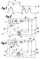
- Figure 1a is the timing diagram obtained with a conventional timer while that 1b shows the timing which can be obtained by the device of the invention.
- the time T determined by the initial setting of the timer index , is equal to the sum of times T 1 , T 2 and T 3 .
- the timer motor is designated by 1, its usual switch by 2 and a manual switch by 3.
- the inventive device is interposed between the source and the device to be supplied such as a television receiver for example.
- 4a and 4b are intended to be connected to the power source; those 5a and 5b, the device supply lines question.
- Une motor terminal is connected to terminal 4 has either switch 2 and the 3, or by a derivative circuit comprising a switch 7 coupled with a second switch interposed 8 on a driver 9 connecting the second terminal of the motor to that 4 b .
- the terminal 5a is connected to a point 6 common to the first terminal of motor 1 and switch 2 while that 5b is connected to terminal 4b .
- the device is completed by a pilot light 10 connected to the terminals of motor 1 and is enclosed in a box 11 whose closing is controlled by a key (not shown) preventing unauthorized persons to modify the setting of the timer index, to act on switch 2 or to have access to terminals 5a and 5b .
- the mounting of the two switches 7 and 8 is such that one is closed when the other is open.
- the control of this set is carried out using a key.
- the switches 7 and 8 are in the state shown in Figure 2 while they are in the state shown in Figure 3 when the key is in place.
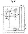
- Figure 4 shows the possibility of making a device comprising two timers and which can be used by two different users, each of which then has its own independent time capital.
- This result is obtained by mounting the motor 12 of the second timer, its switch 13 and the manual switch 14 similar to that 3 according to the same principles as those explained above but by interposing a new manual switch, respectively 15-16, between the first terminal of each of the motors 1-12 and Point 6 common to switches 2-13 and terminal 5 a .
- Switches 3 and 15, as well as those 14 and 16 are mechanically coupled, so as to open or close simultaneously. each of these pairs of manual switches is controlled using a key.
- the present invention extends to all variants within the scope of a person skilled in the art and generally covers a device, one use terminal of which is connected to one source terminal according to two separate circuits, one comprising switches 2 and 3 and the other the switch 7 coupled with that 8 which controls the energization of the motor 1 when a voltage is present at the terminals of use to which said motor is connected.
Landscapes
- Physics & Mathematics (AREA)
- General Physics & Mathematics (AREA)
- Engineering & Computer Science (AREA)
- Automation & Control Theory (AREA)
- Measurement Of Predetermined Time Intervals (AREA)
Applications Claiming Priority (2)
| Application Number | Priority Date | Filing Date | Title |
|---|---|---|---|
| FR7730201 | 1977-10-07 | ||
| FR7730201A FR2405550A1 (fr) | 1977-10-07 | 1977-10-07 | Perfectionnements aux dispositifs de commutation temporisee |
Publications (1)
| Publication Number | Publication Date |
|---|---|
| EP0001459A1 true EP0001459A1 (de) | 1979-04-18 |
Family
ID=9196227
Family Applications (1)
| Application Number | Title | Priority Date | Filing Date |
|---|---|---|---|
| EP78200175A Withdrawn EP0001459A1 (de) | 1977-10-07 | 1978-09-07 | Massnahmen zur Verbesserung von Zeitschalteinrichtungen |
Country Status (2)
| Country | Link |
|---|---|
| EP (1) | EP0001459A1 (de) |
| FR (1) | FR2405550A1 (de) |
Families Citing this family (1)
| Publication number | Priority date | Publication date | Assignee | Title |
|---|---|---|---|---|
| FR2607293A1 (fr) * | 1986-11-24 | 1988-05-27 | Rossillon Philippe | Dispositif infraudable, multifonctions, de limitation du temps de fonctionnement d'un televiseur |
Citations (4)
| Publication number | Priority date | Publication date | Assignee | Title |
|---|---|---|---|---|
| US3046421A (en) * | 1959-03-19 | 1962-07-24 | Holzer Walter | Impulse device connected with a motor in an automatic cut-out for the program control in washing-machines |
| FR2040995A6 (de) * | 1969-04-18 | 1971-01-29 | Dauzier Paul | |
| DE1964352A1 (de) * | 1969-12-23 | 1971-07-01 | Rau Swf Autozubehoer | Schaltungsanordnung fuer einen Zeitschalter mit sehr langen Ausgangsimpulsen |
| FR2319966A1 (fr) * | 1975-07-30 | 1977-02-25 | Nicolas Patrick | Temporisateur pour installation electrique de commande d'au moins un organe mobile a retour automatique |
-
1977
- 1977-10-07 FR FR7730201A patent/FR2405550A1/fr not_active Withdrawn
-
1978
- 1978-09-07 EP EP78200175A patent/EP0001459A1/de not_active Withdrawn
Patent Citations (4)
| Publication number | Priority date | Publication date | Assignee | Title |
|---|---|---|---|---|
| US3046421A (en) * | 1959-03-19 | 1962-07-24 | Holzer Walter | Impulse device connected with a motor in an automatic cut-out for the program control in washing-machines |
| FR2040995A6 (de) * | 1969-04-18 | 1971-01-29 | Dauzier Paul | |
| DE1964352A1 (de) * | 1969-12-23 | 1971-07-01 | Rau Swf Autozubehoer | Schaltungsanordnung fuer einen Zeitschalter mit sehr langen Ausgangsimpulsen |
| FR2319966A1 (fr) * | 1975-07-30 | 1977-02-25 | Nicolas Patrick | Temporisateur pour installation electrique de commande d'au moins un organe mobile a retour automatique |
Also Published As
| Publication number | Publication date |
|---|---|
| FR2405550A1 (fr) | 1979-05-04 |
Similar Documents
| Publication | Publication Date | Title |
|---|---|---|
| FR2458940A1 (fr) | Dispositif d'attaque de moteur a courant continu sans balai | |
| FR2555331A1 (fr) | Circuit comprenant un micro-ordinateur destine notamment au reglage du siege d'un vehicule automobile | |
| EP0680063A1 (de) | Elektrischer Mittelspannungsschalter | |
| FR2591246A1 (fr) | Fer a repasser electrique muni d'un dispositif automatique de securite | |
| EP1042773B1 (de) | Hybrides leistungsrelais | |
| FR2521799A1 (fr) | Dispositif de commande d'un moteur electrique pas a pas | |
| CH620062A5 (de) | ||
| EP0060790A1 (de) | Fehlerstromempfindliche Ausschalter | |
| EP0578555B1 (de) | Pulsgesteuerter Umwandler und elektronische Motorsteuerung | |
| EP0149940B1 (de) | Elektrische Lage-Steueranlage einer sich öffnenden Schiebefläche eines Kraftfahrzeuges | |
| FR2478400A1 (fr) | Dispositif de commande d'un moteur electrique | |
| EP1061650A1 (de) | Bistabiler Zweirichtungs-Hochspannungsschalter | |
| EP0833434B1 (de) | Synchronisationsverfahren- und Vorrichtung für den Anlauf einer dreiphasigen Synchronmaschine | |
| CH629031A5 (fr) | Circuit de commande d'une installation electrique de grande puissance. | |
| FR2660126A1 (fr) | Procede de commande d'un moteur synchrone autopilote et dispositif pour sa mise en óoeuvre. | |
| CH618273A5 (de) | ||
| FR2618233A1 (fr) | Appareil programmable de commutation, notamment pour simulation de presence. | |
| FR2749451A1 (fr) | Procede et dispositif de commande de demarreur de vehicule automobile | |
| FR2525271A1 (fr) | Circuit electrique de commande de leve-vitre pour vehicule | |
| FR2466034A1 (fr) | Dispositif de commande de diaphragme pour appareil de prise de vues photographiques | |
| FR2571186A1 (fr) | Procede et dispositif de commande d'un moteur electrique a alimentation triphasee | |
| FR1461775A (fr) | Appareillage électrique pour actionnement intermittent ou continu d'essuie-glaces, en particulier pour véhicules automobiles | |
| FR2757220A1 (fr) | Perfectionnements aux procedes et aux systemes pour la commande de l'arret automatique d'un demarreur de vehicule automobile | |
| EP0212993B1 (de) | Elektrische ferngesteuerte Anlagen | |
| FR2465618A1 (fr) | Dispositif electronique pour le controle du fonctionnement cadence d'un essuie-glace |
Legal Events
| Date | Code | Title | Description |
|---|---|---|---|
| PUAI | Public reference made under article 153(3) epc to a published international application that has entered the european phase |
Free format text: ORIGINAL CODE: 0009012 |
|
| AK | Designated contracting states |
Designated state(s): BE CH DE GB NL SE |
|
| STAA | Information on the status of an ep patent application or granted ep patent |
Free format text: STATUS: THE APPLICATION IS DEEMED TO BE WITHDRAWN |
|
| 18D | Application deemed to be withdrawn |