EP0001565A1 - Commande électrique pour l'entraînement direct d'une cisaille rotative - Google Patents
Commande électrique pour l'entraînement direct d'une cisaille rotative Download PDFInfo
- Publication number
- EP0001565A1 EP0001565A1 EP78100971A EP78100971A EP0001565A1 EP 0001565 A1 EP0001565 A1 EP 0001565A1 EP 78100971 A EP78100971 A EP 78100971A EP 78100971 A EP78100971 A EP 78100971A EP 0001565 A1 EP0001565 A1 EP 0001565A1
- Authority
- EP
- European Patent Office
- Prior art keywords
- controller
- acceleration
- speed
- path
- cutting
- Prior art date
- Legal status (The legal status is an assumption and is not a legal conclusion. Google has not performed a legal analysis and makes no representation as to the accuracy of the status listed.)
- Granted
Links
- 238000005520 cutting process Methods 0.000 title claims abstract description 53
- 230000001133 acceleration Effects 0.000 claims abstract description 50
- 239000000463 material Substances 0.000 claims abstract description 9
- 230000001360 synchronised effect Effects 0.000 claims abstract description 8
- 230000006870 function Effects 0.000 description 23
- 238000004519 manufacturing process Methods 0.000 description 3
- 238000000034 method Methods 0.000 description 3
- 238000011144 upstream manufacturing Methods 0.000 description 3
- 238000006073 displacement reaction Methods 0.000 description 2
- 230000015654 memory Effects 0.000 description 2
- 230000000630 rising effect Effects 0.000 description 2
- 239000000523 sample Substances 0.000 description 2
- 238000000926 separation method Methods 0.000 description 2
- 238000006467 substitution reaction Methods 0.000 description 2
- 101100521334 Mus musculus Prom1 gene Proteins 0.000 description 1
- 230000001174 ascending effect Effects 0.000 description 1
- 238000010586 diagram Methods 0.000 description 1
- 230000000694 effects Effects 0.000 description 1
- 238000004870 electrical engineering Methods 0.000 description 1
- 238000005461 lubrication Methods 0.000 description 1
- 238000010791 quenching Methods 0.000 description 1
- 239000013589 supplement Substances 0.000 description 1
- 230000007704 transition Effects 0.000 description 1
Images

Classifications
-
- B—PERFORMING OPERATIONS; TRANSPORTING
- B23—MACHINE TOOLS; METAL-WORKING NOT OTHERWISE PROVIDED FOR
- B23D—PLANING; SLOTTING; SHEARING; BROACHING; SAWING; FILING; SCRAPING; LIKE OPERATIONS FOR WORKING METAL BY REMOVING MATERIAL, NOT OTHERWISE PROVIDED FOR
- B23D36/00—Control arrangements specially adapted for machines for shearing or similar cutting, or for sawing, stock which the latter is travelling otherwise than in the direction of the cut
- B23D36/0008—Control arrangements specially adapted for machines for shearing or similar cutting, or for sawing, stock which the latter is travelling otherwise than in the direction of the cut for machines with only one cutting, sawing, or shearing devices
- B23D36/0033—Control arrangements specially adapted for machines for shearing or similar cutting, or for sawing, stock which the latter is travelling otherwise than in the direction of the cut for machines with only one cutting, sawing, or shearing devices for obtaining pieces of a predetermined length
- B23D36/0041—Control arrangements specially adapted for machines for shearing or similar cutting, or for sawing, stock which the latter is travelling otherwise than in the direction of the cut for machines with only one cutting, sawing, or shearing devices for obtaining pieces of a predetermined length the tool moving continuously
-
- B—PERFORMING OPERATIONS; TRANSPORTING
- B26—HAND CUTTING TOOLS; CUTTING; SEVERING
- B26D—CUTTING; DETAILS COMMON TO MACHINES FOR PERFORATING, PUNCHING, CUTTING-OUT, STAMPING-OUT OR SEVERING
- B26D5/00—Arrangements for operating and controlling machines or devices for cutting, cutting-out, stamping-out, punching, perforating, or severing by means other than cutting
- B26D5/38—Arrangements for operating and controlling machines or devices for cutting, cutting-out, stamping-out, punching, perforating, or severing by means other than cutting with means operable by the moving work to initiate the cutting action
- B26D5/40—Arrangements for operating and controlling machines or devices for cutting, cutting-out, stamping-out, punching, perforating, or severing by means other than cutting with means operable by the moving work to initiate the cutting action including a metering device
Definitions
- the invention relates to a circuit arrangement for the direct electrical drive of a rotating cutting device for the format-appropriate cutting of a material web, in particular a flying shear or a synchronous cross cutter, in which a position controller, a speed controller, an acceleration controller and a subordinate current controller are provided.
- the invention has for its object to provide a circuit arrangement of the type mentioned for a time-optimal and path-optimal movement of a rotating separation device.
- this object is achieved in that a computing device is provided, which from predetermined settings and continuously measure the command values for the position controller and the speed controller from measured values for the path.
- Acceleration controller determined in accordance with the equation of motion of the racing device, the output signal of the position controller being applied to the speed controller as a correction variable and the output signal of the speed controller being connected to the acceleration controller as a correcting variable.
- the control arrangement according to the invention works optimally in terms of time because, if necessary, the full acceleration capacity of the drive can be used. Likewise, depending on the machine data and the production speed, the energy required for the acceleration processes and the braking processes of the separating device can also be limited to the extent required for the cutting sequence.
- the control arrangement according to the invention also works optimally because the path and the guide variable for the path covered by the separating device are coupled via the Rochenei device and any deviation from the optimal path of the cutting tool leads to correction via the speed controller.
- the computing device can also limit the web speed and the start-up process depending on form errors. Finally, the computing device can also capture Simplybauma and before 'reaching the target quantity display a message, or automatically stop the production ..
- FIG. 1 shows the structural circuit diagram of a circuit arrangement according to the invention for a synchronous quench.
- a web of material 20 is pulled from an unwind roll and through a pair of knife rollers 18, 19 with knives 23, 24 passed through.
- the knife rollers 18 and 19 are driven in opposite directions by an electrical machine 13.
- the knives 23 and 24 preferably have a small angle of attack with respect to the transverse direction of the material web 20.
- the direct drive for the knife rollers 18 and 19 comprises an electrical machine 13, which is fed via a converter 11 from a three-phase network 12.
- a counter-parallel circuit with two fully controlled three-phase bridges is particularly suitable as the converter.
- the converter 11 is controlled by a control set 10 with ignition pulses, the ignition angle of which is determined by the output voltage of a current regulator 9.
- the current regulator 9 is preceded by a comparator 8, which is acted upon by the output signal I * of an acceleration regulator 7 as a reference variable and by the control variable I of the current control circuit detected by a current measuring transducer 14.
- the comparator 8 forms the control difference for the current controller 9.
- the circuit arrangement shown contains an acceleration controller 7 connected upstream of the current controller 9, a speed controller 5 and a position controller 3, each of which has comparison members connected upstream.
- a digital speed sensor 15 is provided which works according to the principle of an angular step encoder and which consists of a disk which is fixedly connected to the shaft of the drive machine 13 and has a large number of magnetically, electrically or optically recognizable elements evenly distributed over the circumference, a probe scanning these elements and a pulse shaper stage.
- the speed of the drive machine 13 detected by the digital speed sensor 15 is added up in a digital integrator 17, the output signal of which represents a measure of the distance covered by the knives 23 and 24 of the knife rollers 18 and 19 with each revolution.
- the output signal s of the integrator 17 is fed to the comparator 2 in the input of the position controller 3 as a controlled variable for the position control.
- the command variable s * for the position controller 3 is output by a computing device 1.
- the computing device 1 also determines the reference variable n * for the speed controller 5 and the command variable b * for the acceleration controller 7.
- the command variable n * for the speed controller 5 is fed to its comparator 4 together with the output signal n of the position controller 3 as a correction signal and the controlled variable n of the speed control loop.
- the controlled variable n of the speed control loop is the speed of the drive machine 13 detected by the digital speed sensor 15, which is converted into an analog voltage by a digital-analog converter 28, provided the speed controller 5 is designed as an analog controller.
- the reference variable b * for the acceleration controller 7 is fed to its comparator 6 together with the output signal b of the speed controller 5 as a correction signal and the control variable b of the acceleration control loop.
- the controlled variable b of the acceleration control loop is measured as a differential quotient of the speed n of the drive machine 13.
- the speed detected by the digital speed sensor 15, after its implementation in the digital-to-analog converter 28, is guided via a differential generator 16, the output signal b of which represents the actual value of the acceleration of the drive machine 13.
- the output signal I * of the acceleration controller 7 is fed to the comparison element 8 as a reference variable for the current control loop.
- the computing device 1 determines the reference variable s * for the position controller 3, the reference variable n * for the speed controller 5 and the reference variable b * for the acceleration controller 7 from predetermined setting values and from measured values for the path.
- a digital displacement sensor 22 is provided, which is driven, for example, by a friction wheel from the material web 20 running in the direction of the arrow.
- the digital displacement sensor 22, for example likewise has a disk with a large number of magnetically, electrically or optically recognizable elements distributed uniformly over the circumference, which are scanned by a probe, which is followed by a pulse shaper stage.
- a setting value for the format into which the material web 20 is to be divided is specified on a setting device 25.
- Mechanical machine data in particular the path speed and the moment of inertia of the entire arrangement, are specified on a further setting device 26.
- Another setting device 27 sets a limit value for the reference variable b * for the acceleration, which is preferably selected below the maximum acceleration capacity of the drive so that the acceleration controller 7 can intervene in both directions.
- equation (1) eliminates the initial value s o of the path of the cutting edge of the cutting tool.
- equation (1) the path s of the cutting edge of the cutting tool appears as a function of time t.
- the computing device used in the control system according to the invention is intended to calculate the knife path sin as a function of the measured path path x. The equation therefore becomes the substitution of time t (2) inserted in equation (1):
- x means: path
- w path speed
- a graphic representation of the path s of the cutting edge of the cutting tool as a function of the path path x shows a different course of the curve depending on whether a synchronous format, a sub-synchronous format or an oversynchronous format is to be cut.
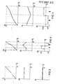
- FIG. 2 shows the path s of the cutting edge of the cutting tool, the speed n of the knife roller and the acceleration b of the separating device in each case as a function of the path x.
- Synchronous format means that the path s1 described by the rotating cutting edge of the cutting tool on a cylinder circumference corresponds to the format x1 to be cut.
- the path function is a straight line with an inclination angle of 45 0 .
- the knife cylinder rotates at a uniform speed.
- the speed function is a horizontal straight line.
- the knife cylinder is neither accelerated nor braked.
- the acceleration is zero.
- FIG. 3 shows the path s of the cutting edge of the cutting tool, the speed n of the knife cylinder and the acceleration b in each case as a function of the path path x.
- Sub-synchronous format means that the path x2 corresponding to the format is smaller than the path s1 described by the rotating cutting edge of the cutting tool on a cylinder circumference. If a sub-synchronous format is to be cut, the speed of the cutting edge of the cutting tool must be equal to the path speed during the cut in order to ensure a smooth cut. Then the knife cylinder accelerates so that the cutting tool overtakes the web. Finally, the knife cylinder is braked back to the web speed.
- the path function is in the cutting phase I a straight line with a slope angle of 45 0, in the acceleration phase II a rising parabola an acceleration parabola and in the braking phase III flattening a parabola of a brake parabola.
- the speed function n shows a horizontal straight line in the cutting phase I, a rising straight line in the acceleration phase II and a falling line in the braking phase III.
- the acceleration function b shows the acceleration value zero in the cutting phase I, a positive acceleration value b2 in the acceleration phase and a deceleration value -b2 of the same size in braking phase III.
- FIG. 4 shows the course of the path s of the cutting edge of the cutting tool, the speed n of the knife cylinder and the acceleration b as a function of the path path x for an oversynchronous format.
- a super-synchronous format means that the path x3 corresponding to the format is larger than the path 1 covered by the rotating cutting edge of the cutting tool on a cylinder circumference Adjust web speed to ensure a smooth cut. Then the knife cylinder is braked and then accelerated again.
- the path function s shows in section phase I a straight line with an inclination angle of 45 °, in the subsequent braking phase III a flattening parabola load of a brake parabola and in acceleration phase II an increasing parabola load of an acceleration parabola.
- the speed function inclines a horizontal straight line in cutting phase I, a falling straight line in brams phase III and an ascending straight line in acceleration phase II.
- the acceleration function b shows the acceleration value zero in the cutting phase I, a negative acceleration value -b3 in the braking phase III and a positive acceleration value b3 in the acceleration phase II.
- the initial speed v of the cutting edge of the cutting tool is equal to the path speed w.
- FIGS. 3 and 4 further show that the parabolic load of the brake parabola is only rotated by 180 ° with respect to the parabola load of the acceleration parabola, the same absolute acceleration values and deceleration values being required. This requirement can be easily met with direct electric drives.
- equation (1a) can be rewritten to equation (1b):
- the functional curves shown in FIGS. 2, 3, 4 are the basis of the calculations to be carried out by the computing device 1 to determine the reference variable s * for the position controller, the reference variable n * for the speed controller and the reference variable b * for the acceleration controller.
- the computing device 1 can determine these reference variables, for example, using function transmitters which emulate the functions shown.
- parabolic interpolation can also be carried out, as described, for example, in Siemens magazine 44, 1970, supplement "Numerical controls", pages 58-62.
- An associated reference variable for the position controller, the speed controller and the acceleration controller can be stored for each travel element detected by the digital travel sensor 22. It is also possible to store various tables for different production programs with different cutting tools and different web speeds.
- the computing device may take over the function of the digital integrator 17, the position controller 3 and the upstream comparison element 2. This does not change the basic functioning of such a circuit arrangement with a position controller included in the computer.
Landscapes
- Engineering & Computer Science (AREA)
- Mechanical Engineering (AREA)
- Life Sciences & Earth Sciences (AREA)
- Forests & Forestry (AREA)
- Numerical Control (AREA)
Applications Claiming Priority (2)
| Application Number | Priority Date | Filing Date | Title |
|---|---|---|---|
| DE19772747022 DE2747022C2 (de) | 1977-10-19 | 1977-10-19 | Schaltungsanordnung für den elektrischen Direktantrieb einer rotierenden Trennvorrichtung |
| DE2747022 | 1977-10-19 |
Publications (2)
| Publication Number | Publication Date |
|---|---|
| EP0001565A1 true EP0001565A1 (fr) | 1979-05-02 |
| EP0001565B1 EP0001565B1 (fr) | 1981-09-02 |
Family
ID=6021807
Family Applications (1)
| Application Number | Title | Priority Date | Filing Date |
|---|---|---|---|
| EP19780100971 Expired EP0001565B1 (fr) | 1977-10-19 | 1978-09-22 | Commande électrique pour l'entraînement direct d'une cisaille rotative |
Country Status (3)
| Country | Link |
|---|---|
| EP (1) | EP0001565B1 (fr) |
| JP (1) | JPS54106979A (fr) |
| DE (1) | DE2747022C2 (fr) |
Cited By (10)
| Publication number | Priority date | Publication date | Assignee | Title |
|---|---|---|---|---|
| EP0046034A1 (fr) * | 1980-08-12 | 1982-02-17 | Hawker Siddeley Canada Inc. | Méthode et dispositif de contrôle de longueurs |
| EP1166977A1 (fr) * | 2000-06-26 | 2002-01-02 | Grapha Holding AG | Machine pour la coupe automatisée d'imprimés |
| WO2002034484A1 (fr) * | 2000-10-26 | 2002-05-02 | Rexroth Indramat Gmbh | Procede et dispositif servant a modifier l'etat d'engagement d'un outil dans une bande de matiere qui defile |
| WO2002074477A1 (fr) * | 2001-03-16 | 2002-09-26 | Stavros Gefiropoulos | Procede et appareil de decoupe d'une feuille metallique dans une installation ou un processus de profilage |
| DE10125609A1 (de) * | 2001-05-25 | 2002-12-05 | Siemens Ag | Regelungsverfahren zum Betrieb von einzeln angetriebenen rotierenden Maschinenelementen |
| DE10132807A1 (de) * | 2001-07-06 | 2003-01-23 | Siemens Ag | Regelungsverfahren und Regelungseinrichtung zum Betrieb von gekoppelten Antriebsachsen mit überlagerten Bewegungskomponenten |
| CN101452257B (zh) * | 2007-11-29 | 2010-06-02 | 宝山钢铁股份有限公司 | 具有头尾剪切补偿的曲柄式飞剪控制方法及装置 |
| US20110284696A1 (en) * | 2010-05-20 | 2011-11-24 | Liebherr-Aerospace Lindenberg Gmbh | Control column system |
| CN102632083A (zh) * | 2012-04-23 | 2012-08-15 | 中冶南方(武汉)自动化有限公司 | 棒材生产线飞剪控制系统末机架轧机工作辊径补偿方法 |
| CN103962384A (zh) * | 2013-01-29 | 2014-08-06 | 宝山钢铁股份有限公司 | 一种热连轧机动态剪切控制方法 |
Families Citing this family (7)
| Publication number | Priority date | Publication date | Assignee | Title |
|---|---|---|---|---|
| DE2812849C2 (de) * | 1978-03-23 | 1985-01-24 | Jagenberg-Werke AG, 4000 Düsseldorf | Verfahren zum Steuern eines Querschneiders und digitale Regeleinrichtung zur Durchführung des Verfahrens |
| JPS5733912A (en) * | 1980-08-02 | 1982-02-24 | Toshiba Corp | Control system of feed cutting equipment |
| JPH0620662B2 (ja) * | 1984-11-30 | 1994-03-23 | 三菱重工業株式会社 | ロ−タリカツタの制御方法 |
| DE3918665A1 (de) * | 1989-06-08 | 1990-12-13 | Bhs Bayerische Berg | Verfahren und vorrichtung zum steuern eines formatlaengengerechten schneidens von materialbahnen |
| DE19739363A1 (de) * | 1997-09-09 | 1999-03-11 | Eska Lager Und Verladesysteme | Vorrichtung zum Messen und Abschneiden von Textilware |
| CN103197537B (zh) * | 2013-03-29 | 2015-07-01 | 中冶南方工程技术有限公司 | 一种冷轧飞剪电机转速的控制方法 |
| CN105195807B (zh) * | 2015-09-11 | 2017-08-29 | 北京首钢股份有限公司 | 一种飞剪剪切方法 |
Citations (5)
| Publication number | Priority date | Publication date | Assignee | Title |
|---|---|---|---|---|
| DE1135997B (de) * | 1961-03-29 | 1962-09-06 | Siemens Ag | Regeleinrichtung fuer den elektrischen Antrieb von rotierenden Scheren |
| DE1502849A1 (de) * | 1964-10-19 | 1970-04-09 | Licentia Gmbh | Verfahren zum Zerschneiden eines bewegten Foerdergutes |
| DE1302871B (fr) * | 1960-01-11 | 1970-11-26 | ||
| US3581613A (en) * | 1969-07-22 | 1971-06-01 | United Eng Foundry Co | Flying shear control |
| DD100594A1 (fr) * | 1972-11-10 | 1973-09-20 |
Family Cites Families (4)
| Publication number | Priority date | Publication date | Assignee | Title |
|---|---|---|---|---|
| JPS5246385B2 (fr) * | 1972-04-15 | 1977-11-24 | ||
| JPS5341830B2 (fr) * | 1973-10-04 | 1978-11-07 | ||
| JPS515108A (ja) * | 1974-07-01 | 1976-01-16 | Choshiro Tokura | Ofusetsutoinsatsuki |
| JPS5151084A (ja) * | 1974-10-29 | 1976-05-06 | Rengo Co Ltd | Shiitosetsudanseigyohoshiki |
-
1977
- 1977-10-19 DE DE19772747022 patent/DE2747022C2/de not_active Expired
-
1978
- 1978-09-22 EP EP19780100971 patent/EP0001565B1/fr not_active Expired
- 1978-10-19 JP JP12904878A patent/JPS54106979A/ja active Pending
Patent Citations (5)
| Publication number | Priority date | Publication date | Assignee | Title |
|---|---|---|---|---|
| DE1302871B (fr) * | 1960-01-11 | 1970-11-26 | ||
| DE1135997B (de) * | 1961-03-29 | 1962-09-06 | Siemens Ag | Regeleinrichtung fuer den elektrischen Antrieb von rotierenden Scheren |
| DE1502849A1 (de) * | 1964-10-19 | 1970-04-09 | Licentia Gmbh | Verfahren zum Zerschneiden eines bewegten Foerdergutes |
| US3581613A (en) * | 1969-07-22 | 1971-06-01 | United Eng Foundry Co | Flying shear control |
| DD100594A1 (fr) * | 1972-11-10 | 1973-09-20 |
Non-Patent Citations (2)
| Title |
|---|
| ARCHIV F]R ELEKTROTECKNIK, Jahrgang 58, Mai 1976, Berlin. W. LEONHARD: "Zeitoptimale Scherenregelung", Seiten 61 bis 67 * |
| SIEMENS-ZEITSCHRIFT, Jahrgang 43, Heft 8, August 1969, Berlin. K. KOOPMANN: "Rotierende S{gen in Rohrwalzwerken", Seiten 690 bis 694 * |
Cited By (16)
| Publication number | Priority date | Publication date | Assignee | Title |
|---|---|---|---|---|
| EP0046034A1 (fr) * | 1980-08-12 | 1982-02-17 | Hawker Siddeley Canada Inc. | Méthode et dispositif de contrôle de longueurs |
| US6796209B2 (en) | 2000-06-26 | 2004-09-28 | Grapha-Holding Ag | Cutting machine for automatic trimming of printed products |
| EP1166977A1 (fr) * | 2000-06-26 | 2002-01-02 | Grapha Holding AG | Machine pour la coupe automatisée d'imprimés |
| WO2002034484A1 (fr) * | 2000-10-26 | 2002-05-02 | Rexroth Indramat Gmbh | Procede et dispositif servant a modifier l'etat d'engagement d'un outil dans une bande de matiere qui defile |
| US7089078B2 (en) | 2000-10-26 | 2006-08-08 | Rexroth Indramat Gmbh | Method and device for adjusting the degree of engagement of a tool with a web of a materail running past it |
| WO2002074477A1 (fr) * | 2001-03-16 | 2002-09-26 | Stavros Gefiropoulos | Procede et appareil de decoupe d'une feuille metallique dans une installation ou un processus de profilage |
| DE10125609A1 (de) * | 2001-05-25 | 2002-12-05 | Siemens Ag | Regelungsverfahren zum Betrieb von einzeln angetriebenen rotierenden Maschinenelementen |
| US6714843B2 (en) | 2001-05-25 | 2004-03-30 | Siemens Aktiengesellschaft | Closed-loop control method for operation of individually driven rotating machine elements |
| DE10132807A1 (de) * | 2001-07-06 | 2003-01-23 | Siemens Ag | Regelungsverfahren und Regelungseinrichtung zum Betrieb von gekoppelten Antriebsachsen mit überlagerten Bewegungskomponenten |
| DE10132807B4 (de) * | 2001-07-06 | 2006-10-12 | Siemens Ag | Regelungsverfahren und Regelungseinrichtung zum Betrieb von gekoppelten Antriebsachsen mit überlagerten Bewegungskomponenten |
| DE10132807C5 (de) * | 2001-07-06 | 2009-01-08 | Siemens Ag | Regelungsverfahren zum Betrieb von gekoppelten Antriebsachsen mit überlagerten Bewegungskomponenten |
| CN101452257B (zh) * | 2007-11-29 | 2010-06-02 | 宝山钢铁股份有限公司 | 具有头尾剪切补偿的曲柄式飞剪控制方法及装置 |
| US20110284696A1 (en) * | 2010-05-20 | 2011-11-24 | Liebherr-Aerospace Lindenberg Gmbh | Control column system |
| CN102632083A (zh) * | 2012-04-23 | 2012-08-15 | 中冶南方(武汉)自动化有限公司 | 棒材生产线飞剪控制系统末机架轧机工作辊径补偿方法 |
| CN102632083B (zh) * | 2012-04-23 | 2014-02-19 | 中冶南方(武汉)自动化有限公司 | 棒材生产线飞剪控制系统末机架轧机工作辊径补偿方法 |
| CN103962384A (zh) * | 2013-01-29 | 2014-08-06 | 宝山钢铁股份有限公司 | 一种热连轧机动态剪切控制方法 |
Also Published As
| Publication number | Publication date |
|---|---|
| DE2747022A1 (de) | 1979-04-26 |
| DE2747022C2 (de) | 1985-05-15 |
| EP0001565B1 (fr) | 1981-09-02 |
| JPS54106979A (en) | 1979-08-22 |
Similar Documents
| Publication | Publication Date | Title |
|---|---|---|
| EP0001565B1 (fr) | Commande électrique pour l'entraînement direct d'une cisaille rotative | |
| DE2525341C2 (de) | Vorrichtung und Verfahren zur Steuerung einer kontinuierlich geförderten Bahn | |
| DE2452756A1 (de) | Zufuehrungsvorrichtung fuer ein in eine druckmaschine einlaufendes materialband, vorzugsweise aus papier oder pappe | |
| DE2937838C2 (de) | Verfahren und Anordnung zur Regelung von Drehzahl und Phasenlage bei Synchronmotoren | |
| DE2428219C2 (de) | Einrichtung zum Steuern und Regeln von Schnittabstand und Gleichlauf an einem Bandmaterial bearbeitenden Schneidgerät | |
| DE2934775C2 (de) | Servopositioniersystem | |
| DE2856817C2 (fr) | ||
| DE3513775A1 (de) | Steuereinheit fuer einen von einem frequenzumrichter gespeisten drehstrommotorantrieb | |
| DE2458763C2 (de) | Drehzahlregelkreis mit überlagerter Wegregelung für rotierende Scheren oder auf Schlitten geführte Zerteilvorrichtungen im Anlauf- oder Durchlaufbetrieb | |
| EP0469177B1 (fr) | Procédé et dispositif pour le redémarrage d'un moteur à induction | |
| DE3301091C2 (de) | Einrichtung zur Steuerung eines Elektromotors als Antriebsorgan für eine horizontale Bewegung eines Hebezeugs | |
| DE2522634C2 (de) | Ablängmaschine für Draht und schlauchförmiges Gut | |
| EP2290808A1 (fr) | Procédé de détermination du facteur d'échelonnage d'un système d'entraînement électrique ainsi que dispositif correspondant et système d'entraînement électrique correspondant | |
| DE2619299C3 (de) | Elektronische Einrichtung zur Ermittlung des Ungleichförmigkeitsgrades einer von einer gleichförmigen Bewegung abgeleiteten ungleichförmigen Bewegung | |
| DE1513248A1 (de) | Verfahren zur Regelung der Lage bei fliegenden Rotationsscheren | |
| DE1032372B (de) | Verfahren zur selbsttaetigen Steuerung der elektromotorischen Antriebe von Zerteilanlagen fuer durchlaufendes Gut | |
| DE2535108C2 (de) | Verfahren zur Regelung des Antriebes eines ein Schneidwerkzeug aufweisenden Schneideschlittens eines Abschneiders zum Unterteilen eines endlosen Tonstranges | |
| DE1463590C3 (de) | Drehzahlregeleinrichtung für eine rotierende oder auf schlitten geführte zerteilvorrichtungen | |
| DE961204C (de) | Bremseinrichtung fuer Aufzuege | |
| DE2812849C2 (de) | Verfahren zum Steuern eines Querschneiders und digitale Regeleinrichtung zur Durchführung des Verfahrens | |
| DE2063455A1 (de) | Steuereinrichtung fur eine Band schneidanlage | |
| DE2452385C2 (de) | Einrichtung zum Steuern und Regeln von Schnittabstand und Gleichlauf an einem Bandmaterial bearbeitenden Schneidgerät | |
| DE3719580C2 (fr) | ||
| DE3308671A1 (de) | Regelkreis fuer einen antrieb | |
| EP4715502A1 (fr) | Régulation d'une grandeur technique avec cascade de régulation |
Legal Events
| Date | Code | Title | Description |
|---|---|---|---|
| PUAI | Public reference made under article 153(3) epc to a published international application that has entered the european phase |
Free format text: ORIGINAL CODE: 0009012 |
|
| AK | Designated contracting states |
Designated state(s): BE CH DE FR SE |
|
| 17P | Request for examination filed | ||
| GRAA | (expected) grant |
Free format text: ORIGINAL CODE: 0009210 |
|
| AK | Designated contracting states |
Designated state(s): BE CH FR SE |
|
| PGFP | Annual fee paid to national office [announced via postgrant information from national office to epo] |
Ref country code: SE Payment date: 19920909 Year of fee payment: 15 |
|
| PGFP | Annual fee paid to national office [announced via postgrant information from national office to epo] |
Ref country code: BE Payment date: 19920915 Year of fee payment: 15 |
|
| PGFP | Annual fee paid to national office [announced via postgrant information from national office to epo] |
Ref country code: FR Payment date: 19920917 Year of fee payment: 15 |
|
| PGFP | Annual fee paid to national office [announced via postgrant information from national office to epo] |
Ref country code: CH Payment date: 19921215 Year of fee payment: 15 |
|
| PG25 | Lapsed in a contracting state [announced via postgrant information from national office to epo] |
Ref country code: SE Effective date: 19930923 |
|
| PG25 | Lapsed in a contracting state [announced via postgrant information from national office to epo] |
Ref country code: CH Effective date: 19930930 Ref country code: BE Effective date: 19930930 |
|
| BERE | Be: lapsed |
Owner name: SIEMENS A.G. BERLIN UND MUNCHEN Effective date: 19930930 |
|
| PG25 | Lapsed in a contracting state [announced via postgrant information from national office to epo] |
Ref country code: FR Free format text: LAPSE BECAUSE OF NON-PAYMENT OF DUE FEES Effective date: 19940531 |
|
| REG | Reference to a national code |
Ref country code: CH Ref legal event code: PL |
|
| REG | Reference to a national code |
Ref country code: FR Ref legal event code: ST |
|
| EUG | Se: european patent has lapsed |
Ref document number: 78100971.7 Effective date: 19940410 |
|
| PLBE | No opposition filed within time limit |
Free format text: ORIGINAL CODE: 0009261 |
|
| STAA | Information on the status of an ep patent application or granted ep patent |
Free format text: STATUS: NO OPPOSITION FILED WITHIN TIME LIMIT |