EP0001606A1 - Isolation thermique et acoustique pour un tuyau coudé, procédé et dispositif pour sa fabrication - Google Patents
Isolation thermique et acoustique pour un tuyau coudé, procédé et dispositif pour sa fabrication Download PDFInfo
- Publication number
- EP0001606A1 EP0001606A1 EP78101101A EP78101101A EP0001606A1 EP 0001606 A1 EP0001606 A1 EP 0001606A1 EP 78101101 A EP78101101 A EP 78101101A EP 78101101 A EP78101101 A EP 78101101A EP 0001606 A1 EP0001606 A1 EP 0001606A1
- Authority
- EP
- European Patent Office
- Prior art keywords
- mold
- shells
- insulating body
- film
- protective jacket
- Prior art date
- Legal status (The legal status is an assumption and is not a legal conclusion. Google has not performed a legal analysis and makes no representation as to the accuracy of the status listed.)
- Withdrawn
Links
- 238000009413 insulation Methods 0.000 title claims abstract description 30
- 238000000034 method Methods 0.000 title claims description 18
- 230000001681 protective effect Effects 0.000 claims abstract description 44
- 238000010438 heat treatment Methods 0.000 claims description 12
- 238000004519 manufacturing process Methods 0.000 claims description 6
- 239000006260 foam Substances 0.000 claims description 5
- 238000005187 foaming Methods 0.000 claims description 3
- 239000000463 material Substances 0.000 claims description 3
- XLYOFNOQVPJJNP-UHFFFAOYSA-N water Substances O XLYOFNOQVPJJNP-UHFFFAOYSA-N 0.000 claims description 3
- 229920005830 Polyurethane Foam Polymers 0.000 claims description 2
- 229920002635 polyurethane Polymers 0.000 claims description 2
- 239000004814 polyurethane Substances 0.000 claims description 2
- 239000011496 polyurethane foam Substances 0.000 claims description 2
- 229920001971 elastomer Polymers 0.000 claims 1
- 210000000056 organ Anatomy 0.000 claims 1
- 239000011888 foil Substances 0.000 abstract description 3
- 230000000284 resting effect Effects 0.000 abstract description 3
- 238000000465 moulding Methods 0.000 description 14
- 239000004793 Polystyrene Substances 0.000 description 4
- 229920006328 Styrofoam Polymers 0.000 description 2
- 238000009434 installation Methods 0.000 description 2
- 230000035515 penetration Effects 0.000 description 2
- 239000008261 styrofoam Substances 0.000 description 2
- 239000011324 bead Substances 0.000 description 1
- 230000015572 biosynthetic process Effects 0.000 description 1
- 239000007799 cork Substances 0.000 description 1
- 238000006073 displacement reaction Methods 0.000 description 1
- 230000000694 effects Effects 0.000 description 1
- 239000011810 insulating material Substances 0.000 description 1
- 239000011505 plaster Substances 0.000 description 1
- 239000004033 plastic Substances 0.000 description 1
- 229920003023 plastic Polymers 0.000 description 1
- 239000011148 porous material Substances 0.000 description 1
- 238000007493 shaping process Methods 0.000 description 1
- 238000003856 thermoforming Methods 0.000 description 1
- 210000002268 wool Anatomy 0.000 description 1
Images

Classifications
-
- B—PERFORMING OPERATIONS; TRANSPORTING
- B29—WORKING OF PLASTICS; WORKING OF SUBSTANCES IN A PLASTIC STATE IN GENERAL
- B29C—SHAPING OR JOINING OF PLASTICS; SHAPING OF MATERIAL IN A PLASTIC STATE, NOT OTHERWISE PROVIDED FOR; AFTER-TREATMENT OF THE SHAPED PRODUCTS, e.g. REPAIRING
- B29C51/00—Shaping by thermoforming, i.e. shaping sheets or sheet like preforms after heating, e.g. shaping sheets in matched moulds or by deep-drawing; Apparatus therefor
-
- B—PERFORMING OPERATIONS; TRANSPORTING
- B29—WORKING OF PLASTICS; WORKING OF SUBSTANCES IN A PLASTIC STATE IN GENERAL
- B29C—SHAPING OR JOINING OF PLASTICS; SHAPING OF MATERIAL IN A PLASTIC STATE, NOT OTHERWISE PROVIDED FOR; AFTER-TREATMENT OF THE SHAPED PRODUCTS, e.g. REPAIRING
- B29C33/00—Moulds or cores; Details thereof or accessories therefor
- B29C33/0011—Moulds or cores; Details thereof or accessories therefor thin-walled moulds
- B29C33/0016—Lost moulds, e.g. staying on the moulded object
-
- B—PERFORMING OPERATIONS; TRANSPORTING
- B29—WORKING OF PLASTICS; WORKING OF SUBSTANCES IN A PLASTIC STATE IN GENERAL
- B29C—SHAPING OR JOINING OF PLASTICS; SHAPING OF MATERIAL IN A PLASTIC STATE, NOT OTHERWISE PROVIDED FOR; AFTER-TREATMENT OF THE SHAPED PRODUCTS, e.g. REPAIRING
- B29C33/00—Moulds or cores; Details thereof or accessories therefor
- B29C33/44—Moulds or cores; Details thereof or accessories therefor with means for, or specially constructed to facilitate, the removal of articles, e.g. of undercut articles
- B29C33/48—Moulds or cores; Details thereof or accessories therefor with means for, or specially constructed to facilitate, the removal of articles, e.g. of undercut articles with means for collapsing or disassembling
- B29C33/485—Moulds or cores; Details thereof or accessories therefor with means for, or specially constructed to facilitate, the removal of articles, e.g. of undercut articles with means for collapsing or disassembling cores or mandrels
-
- B—PERFORMING OPERATIONS; TRANSPORTING
- B29—WORKING OF PLASTICS; WORKING OF SUBSTANCES IN A PLASTIC STATE IN GENERAL
- B29C—SHAPING OR JOINING OF PLASTICS; SHAPING OF MATERIAL IN A PLASTIC STATE, NOT OTHERWISE PROVIDED FOR; AFTER-TREATMENT OF THE SHAPED PRODUCTS, e.g. REPAIRING
- B29C51/00—Shaping by thermoforming, i.e. shaping sheets or sheet like preforms after heating, e.g. shaping sheets in matched moulds or by deep-drawing; Apparatus therefor
- B29C51/16—Lining or labelling
-
- B—PERFORMING OPERATIONS; TRANSPORTING
- B29—WORKING OF PLASTICS; WORKING OF SUBSTANCES IN A PLASTIC STATE IN GENERAL
- B29C—SHAPING OR JOINING OF PLASTICS; SHAPING OF MATERIAL IN A PLASTIC STATE, NOT OTHERWISE PROVIDED FOR; AFTER-TREATMENT OF THE SHAPED PRODUCTS, e.g. REPAIRING
- B29C51/00—Shaping by thermoforming, i.e. shaping sheets or sheet like preforms after heating, e.g. shaping sheets in matched moulds or by deep-drawing; Apparatus therefor
- B29C51/26—Component parts, details or accessories; Auxiliary operations
- B29C51/30—Moulds
-
- F—MECHANICAL ENGINEERING; LIGHTING; HEATING; WEAPONS; BLASTING
- F16—ENGINEERING ELEMENTS AND UNITS; GENERAL MEASURES FOR PRODUCING AND MAINTAINING EFFECTIVE FUNCTIONING OF MACHINES OR INSTALLATIONS; THERMAL INSULATION IN GENERAL
- F16L—PIPES; JOINTS OR FITTINGS FOR PIPES; SUPPORTS FOR PIPES, CABLES OR PROTECTIVE TUBING; MEANS FOR THERMAL INSULATION IN GENERAL
- F16L59/00—Thermal insulation in general
- F16L59/10—Bandages or covers for the protection of the insulation, e.g. against the influence of the environment or against mechanical damage
- F16L59/11—Rigid covers for elbows
-
- F—MECHANICAL ENGINEERING; LIGHTING; HEATING; WEAPONS; BLASTING
- F16—ENGINEERING ELEMENTS AND UNITS; GENERAL MEASURES FOR PRODUCING AND MAINTAINING EFFECTIVE FUNCTIONING OF MACHINES OR INSTALLATIONS; THERMAL INSULATION IN GENERAL
- F16L—PIPES; JOINTS OR FITTINGS FOR PIPES; SUPPORTS FOR PIPES, CABLES OR PROTECTIVE TUBING; MEANS FOR THERMAL INSULATION IN GENERAL
- F16L59/00—Thermal insulation in general
- F16L59/14—Arrangements for the insulation of pipes or pipe systems
- F16L59/16—Arrangements specially adapted to local requirements at flanges, junctions, valves or the like
- F16L59/22—Arrangements specially adapted to local requirements at flanges, junctions, valves or the like adapted for bends
-
- B—PERFORMING OPERATIONS; TRANSPORTING
- B29—WORKING OF PLASTICS; WORKING OF SUBSTANCES IN A PLASTIC STATE IN GENERAL
- B29L—INDEXING SCHEME ASSOCIATED WITH SUBCLASS B29C, RELATING TO PARTICULAR ARTICLES
- B29L2023/00—Tubular articles
-
- B—PERFORMING OPERATIONS; TRANSPORTING
- B29—WORKING OF PLASTICS; WORKING OF SUBSTANCES IN A PLASTIC STATE IN GENERAL
- B29L—INDEXING SCHEME ASSOCIATED WITH SUBCLASS B29C, RELATING TO PARTICULAR ARTICLES
- B29L2023/00—Tubular articles
- B29L2023/22—Tubes or pipes, i.e. rigid
- B29L2023/225—Insulated
Definitions
- the invention relates to an insulation for a pipe bend against cold, noise and heat consisting of two half shells of the same shape that can be placed on the pipe bend, which form a tubular insulating body, and a protective sheath covering the outside of the joined half shells, and to a method and a device for manufacturing the same.
- an insulation layer is known to be placed around the pipeline, over which a protective jacket is applied, in order to protect the layer against moisture and mechanical damage.
- a layer of insulating material consisting of coiled braids, strands, mats, wool or cork is placed around the pipe bend. Then a protective jacket is wrapped around the layer and fastened, creating the insulation.
- Various types of insulation for pipe bends are known. Some are designed as two-part molded parts with or without an outer protective jacket. Shaped parts without an insulating jacket are made of pressed styrofoam and have the disadvantage that they have to be reworked by hand on one or both front edges due to the lack of elasticity when applied to a pipe bend that is not installed correctly, and break out in the process. Other molded parts consist of rigid foams that are molded or machined, e.g. milled and have the same disadvantages as styrofoam.
- an insulating body made of semi-rigid material, which is provided with notch-shaped cutouts running transversely to its axis, in such a way that it can be folded into a bend, the cutouts extending from T-shaped cuts into the Extend edges.
- the disadvantage of this insulating body is that it has open pores into which condensed water can penetrate. Furthermore, due to the inaccurate contact of the individual sections between the wedge-shaped incisions, the condensed water can also penetrate the insulating bodies from the inside, and gaps can arise which considerably reduce the insulating capacity of the insulation.
- a protective jacket is required to protect the above-mentioned insulating body from mechanical damage, which is deep-drawn in a separate form and arranged in a separate operation using tools on the respective pipe bend and then finally is attached.
- the costs per assembled sheet are very high.
- a pipe bend insulation which consists of two shaped halves.
- the halves consist of a protective jacket in the form of a pipe bend half-shell and an insulating body, which is foamed in a specially prepared form in the pipe bend half-shell.
- the insulating bodies are provided with recesses using various cores.
- the halves are provided with snap closures, which are attached zen of the counter halves interlock positively and can be non-detachably connected by the snap locks.
- CH-PS No. 453 016, CH-PS No. 547 669, DT-OS No. 2 353 308, DT-GB No. 1 754 657, CH-PS No. 564 723 and CH-PS No. 542 397 discloses methods and methods and devices for producing a protective jacket, with which a one-piece protective jacket can be produced.
- sheets and foils made of thermoformable material e.g. Plastic is thermoformed or vacuum-formed in a mold in a known manner. Different shapes are used for this, so that different shell-shaped protective sheaths are created.
- these protective shells have the disadvantage that they are dimensionally stable only in the bent, shell-like state.
- the invention as characterized in the claims, achieves the object of providing insulation for a pipe bend and a method and a device for producing the insulation which do not have the disadvantages mentioned above.
- the advantages of the invention consist in the fact that the insulation consisting of half-shells and protective jacket is designed as a universal component that can be mounted on different types of pipe bends and designs, whereby the installation can be carried out simply and quickly, that the number of types of insulation, the outer diameter of which is determined solely by the outer diameter of the insulation adjacent piping is determined, due to the formation of the recess, in which all types and designs of bends can be reduced, and that the number of molds can be greatly reduced by deep-drawing the protective jacket by means of the lost shape can.
- the insulation can be used for other pipe widths with a small insulation thickness, as a result of which a further considerable reduction in the number of versions of the insulation according to the invention can be achieved.
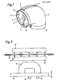
- the insulating body 1 consists of two half-shells la, lb of the same shape, which can be glued together on the outer abutting surfaces, so that a tubular body is formed, a slot 3 being present between the inner abutting surfaces.
- the half-shells are foamed in a form known per se, into which a core is inserted, from a foam amount of 30-80 kg / m 3 .
- the half-shells can consist of polyurethane integral foam which has a skin which is closed on all sides and which protects the insulating body 1 against the penetration of moisture and is elastically deformable.
- the half-shells can also consist of rigid polyurethane foam, which has cells which are closed per se, so that the penetration of moisture is prevented, but is not elastically deformable.
- the insulating body 1 formed from the half-shells has a specific outer arch shape and has two end faces 4 with the same outer diameter. This outer arch shape and the diameters assigned to it form a characteristic of the insulation.
- a core (not shown) is used when foaming the half-shells in order to be able to isolate different types and designs of pipe elbows with different radii of curvature. This significantly reduces the number of foam tools.
- the protective jacket 2 lies against the insulating body 1.
- a section 6 is formed at each end of the protective jacket 2, over which the protective jacket of the subsequent insulation (not shown) is pushed and glued to it.
- a meridional bead 7 is provided on the outside of the protective jacket in order to make room for any unevenness that may occur on the insulating body 1 speed that can arise when the half-shells la, lb are joined together.
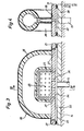
- a device for producing the protective jacket is shown schematically.
- the device essentially consists of a heating device 10 for heating a film 11, a clamping frame 12 for holding the film, a molding tool 13, a table 14 on which the molding tool is arranged and a vacuum and compressed air line 15 or 16.
- the heating device 10 is arranged such that it can be positioned above and / or below the film for heating. After heating, the heating device 10 is removed and the table 14 with the molding tool 13 is moved against the film. In order to improve the drawing of the film, the film 11 is blown through a line (not shown), whereby it is bulged. The molding tool is inserted into this curvature until the table 14 rests on the clamping frame 12. A vacuum is then created in the space created between the film and the mold, causing the film 11 to contact the mold. After the film has cooled, the table 4 is lowered.
- FIG. 3 shows two exemplary embodiments of a molding tool that can be used in the device according to FIG. 2. Both embodiments have so-called lost forms, i.e. a new mold is used or inflated for each deep-drawing process.
- the molding tool shown in FIGS. 3 and 4 has a base plate 20 which is attached to the table 14.
- a shaped plate 21 is arranged above the base plate 20.
- a planing chamber 22, into which the vacuum line 15 opens, is provided between the base plate 20 and the molding plate 21.
- a holding member 23 is arranged on the upper side of the molding plate 21. The holding member 23 is cuboid and on one long side firmly connected to the mold plate 21. In the holding member 23 there is a rectangular recess 24 and holes 25 are provided which open into the recess. Bores 26 are provided in the mold plate 21, which connect the recess 24 to the cavity 22 below the mold plate 21.
- a shape is attached to the holding member 23.
- the shape is an insulating body 36 formed from half-shells.
- the half-shells are designed as one-piece molded parts which are connected to the ends forming the end faces of the insulating body and are glued to one another on the outer abutting surfaces.
- the insulating body 36 rests with the other end faces on the molding plate 21 and is secured against lateral displacement by the holding member 23, which protrudes into the slot in the insulating body 36.
- Holes 27 are further provided in the base plate 21, which are arranged in a circular arc next to the holding part 23.
- the radius of the circular arc is somewhat larger than the radius of the circular end face of the insulating body 36 resting on the base plate 21.
- the holes 27 open into the cavity 22, which is connected to the vacuum line 15.
- the molding tool described above is inserted into the device according to FIG. 2. After the thermoforming of the film, as described in connection with FIG. 2, the insulating body 36 with the protective jacket 28 lying thereon is lifted off the base plate 21. A new insulating body 36 is then placed on the base plate 21 and the deep-drawing process is started again.
- the insulating body 36 is formed from half-shells which consist of two quarter arches connected to one another on the end faces.
- the insulating body 36 and the protective jacket 28 resting thereon are now separated from one another by a suitable method, so that two quarter arches are formed, one of which is shown in FIG. 1.
- the molding tool has a base plate 20 which is attached to the table 14.
- a shaped plate 21 is arranged above the base plate 20.
- a cavity 22 is provided between the base plate 20 and the molding plate 21, into which the vacuum line 15 opens.
- the mold which consists of a tubular, elastically deformable part 29, is fastened to the top of the mold plate 21.
- the part 29 is at the open ends by a holding device consisting of a round disc 30 which is attached to the front plate 21, e.g. is held by screws 31, and a retaining ring 32, between the inner surface and the outer surface of the disc 30, the tubular part 29 is clamped.
- a support member 34 is provided within the tubular part 29 and is attached to the disks 30.
- a pressure line 16 opens into the tubular part 29 fastened to the disks 30.
- the tubular part 29 is inflatable and, in the inflated state, has the shape of an insulating body 36 analogous to FIGS. 3 and 4.
- a cuboid part is arranged between the hoses, which is designed and fastened analogously to the holding member 23 in FIG. 3.
- the part 23 has a rectangular recess 24 and is provided with holes 25 which open into the recess 24.
- the rectangular recess 24 is connected to the cavity 22 below the mold plate 21 via the holes 26 provided in the mold plate 21.
- Holes 27 opening into the cavity 22 are furthermore provided in the mold plate 21 and are arranged lying on a circular arc at a distance from the holding device for the hose.
- a protective jacket for an insulating body, the outer one of which, can be pulled Shape corresponds to the inflated, tubular part 29.
- the tubular part 29 is inflated via the pressure line 16.
- the pressure in the line 16 is approximately 3 atm to give the tubular part 29 a certain dimensional stability in the inflated state.
- the deep-drawing process is carried out with the inflated part 29 in the manner described in connection with FIG. 2 in order to produce a protective jacket.
- the pressure in the tubular part 29 is reduced, the part 29 taking on approximately the shape shown in FIG. 6 by means of dash-dotted lines.
- the protective jacket can then be removed from the tubular part 29.
- the protective jacket is then mechanically processed so that two quarter arches are created, one of which is shown in FIG. 1.
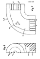
- the half-shell la, lb has the shape of a quarter arch and a semicircular cross section. Cutouts 41 with a semicircular cross section are formed in the sections 40 at the ends of the half-shell. Grooves 42 are also provided in section 40, which are spaced apart from one another and formed parallel to one another. These grooves 42 serve as markings if the half-shell is to be adapted to a tube which cannot be detected by the cutout originally provided. A curved recess, which also has a semicircular cross section, extends between these sections. A bulge 44 is formed in the central region of the recess 43 and protrudes into the outer wall part of the half-shell.
- Two cylindrical projections 45 are provided in the recess 43, which protrude perpendicularly from the surface of the recess 44.
- the projections are formed in one piece with the half-shell la, lb.
- the projections 45 serve to support the elbow lying in the recess.
- the projections 45 when mounting the half-shells la, lb respectively shortened or completely removed.
Landscapes
- Engineering & Computer Science (AREA)
- Mechanical Engineering (AREA)
- General Engineering & Computer Science (AREA)
- Steering Controls (AREA)
- Thermal Insulation (AREA)
Applications Claiming Priority (2)
| Application Number | Priority Date | Filing Date | Title |
|---|---|---|---|
| AT7430/77 | 1977-10-17 | ||
| AT743077A ATA743077A (de) | 1977-10-17 | 1977-10-17 | Verfahren und vorrichtung zur herstellung einer isolierung fuer einen rohrbogen gegen kaelte, schall und waerme |
Publications (1)
| Publication Number | Publication Date |
|---|---|
| EP0001606A1 true EP0001606A1 (fr) | 1979-05-02 |
Family
ID=3595975
Family Applications (1)
| Application Number | Title | Priority Date | Filing Date |
|---|---|---|---|
| EP78101101A Withdrawn EP0001606A1 (fr) | 1977-10-17 | 1978-10-09 | Isolation thermique et acoustique pour un tuyau coudé, procédé et dispositif pour sa fabrication |
Country Status (4)
| Country | Link |
|---|---|
| EP (1) | EP0001606A1 (fr) |
| AT (1) | ATA743077A (fr) |
| DK (1) | DK460478A (fr) |
| NO (1) | NO783483L (fr) |
Cited By (3)
| Publication number | Priority date | Publication date | Assignee | Title |
|---|---|---|---|---|
| AT383200B (de) * | 1984-09-28 | 1987-05-25 | Steinbacher Eduard | Verfahren zur herstellung einer isolierung fuer ein ventil od.dgl. |
| CN106801770A (zh) * | 2017-03-21 | 2017-06-06 | 叶雨玲 | 一种农田灌溉用输水管道加强装置 |
| DE102016005757A1 (de) * | 2016-05-10 | 2017-11-16 | AUSTROFLEX Rohr-lsoliersysteme GmbH | Isolierelement für wärmeführende Leitung |
Citations (8)
| Publication number | Priority date | Publication date | Assignee | Title |
|---|---|---|---|---|
| US1771134A (en) * | 1927-11-14 | 1930-07-22 | Morgan Clarence Stanley | Insulation for pipe fittings |
| DE1454979A1 (de) * | 1965-01-27 | 1969-05-08 | Bosch Hausgeraete Gmbh | Verfahren zum UEberziehen von Formkoerpern aus waermeisolierendem Stoff mit einer Abdeckung |
| US3598157A (en) * | 1969-08-04 | 1971-08-10 | Owens Corning Fiberglass Corp | Insulation for pipe fitting |
| CH542397A (de) * | 1971-02-15 | 1973-09-30 | Muellender Gernot | Elastischer Folienbogen zum Umkleiden von Rohrkrümmern und Verfahren zu seiner Herstellung |
| DE2322314A1 (de) * | 1973-05-03 | 1974-11-14 | Ernst Keutner | Rohrbogen zum verkleiden einer isolierungsschicht |
| DE2353308A1 (de) * | 1973-10-24 | 1975-05-07 | Ernst Keutner | Einstueckiger rohrbogen zum ummanteln einer waerme-, kaelte- oder schallisolierung und verfahren zu seiner herstellung |
| CH564723A5 (fr) * | 1973-05-14 | 1975-07-31 | Schibig Arthur | |
| US3960180A (en) * | 1973-03-01 | 1976-06-01 | Aktiebolaget M. Anderssons Isolering | Protection cover for pipe bends |
-
1977
- 1977-10-17 AT AT743077A patent/ATA743077A/de unknown
-
1978
- 1978-10-09 EP EP78101101A patent/EP0001606A1/fr not_active Withdrawn
- 1978-10-13 NO NO783483A patent/NO783483L/no unknown
- 1978-10-16 DK DK460478A patent/DK460478A/da unknown
Patent Citations (8)
| Publication number | Priority date | Publication date | Assignee | Title |
|---|---|---|---|---|
| US1771134A (en) * | 1927-11-14 | 1930-07-22 | Morgan Clarence Stanley | Insulation for pipe fittings |
| DE1454979A1 (de) * | 1965-01-27 | 1969-05-08 | Bosch Hausgeraete Gmbh | Verfahren zum UEberziehen von Formkoerpern aus waermeisolierendem Stoff mit einer Abdeckung |
| US3598157A (en) * | 1969-08-04 | 1971-08-10 | Owens Corning Fiberglass Corp | Insulation for pipe fitting |
| CH542397A (de) * | 1971-02-15 | 1973-09-30 | Muellender Gernot | Elastischer Folienbogen zum Umkleiden von Rohrkrümmern und Verfahren zu seiner Herstellung |
| US3960180A (en) * | 1973-03-01 | 1976-06-01 | Aktiebolaget M. Anderssons Isolering | Protection cover for pipe bends |
| DE2322314A1 (de) * | 1973-05-03 | 1974-11-14 | Ernst Keutner | Rohrbogen zum verkleiden einer isolierungsschicht |
| CH564723A5 (fr) * | 1973-05-14 | 1975-07-31 | Schibig Arthur | |
| DE2353308A1 (de) * | 1973-10-24 | 1975-05-07 | Ernst Keutner | Einstueckiger rohrbogen zum ummanteln einer waerme-, kaelte- oder schallisolierung und verfahren zu seiner herstellung |
Cited By (4)
| Publication number | Priority date | Publication date | Assignee | Title |
|---|---|---|---|---|
| AT383200B (de) * | 1984-09-28 | 1987-05-25 | Steinbacher Eduard | Verfahren zur herstellung einer isolierung fuer ein ventil od.dgl. |
| DE102016005757A1 (de) * | 2016-05-10 | 2017-11-16 | AUSTROFLEX Rohr-lsoliersysteme GmbH | Isolierelement für wärmeführende Leitung |
| CN106801770A (zh) * | 2017-03-21 | 2017-06-06 | 叶雨玲 | 一种农田灌溉用输水管道加强装置 |
| CN106801770B (zh) * | 2017-03-21 | 2019-04-02 | 中苏科技股份有限公司 | 一种农田灌溉用输水管道加强装置 |
Also Published As
| Publication number | Publication date |
|---|---|
| ATA743077A (de) | 1980-11-15 |
| DK460478A (da) | 1979-04-18 |
| NO783483L (no) | 1979-04-18 |
Similar Documents
| Publication | Publication Date | Title |
|---|---|---|
| EP0210587B1 (fr) | Procédé de fabrication d'un élément de rembourrage et dispositif pour la mise en oeuvre de ce procédé | |
| DE8702212U1 (de) | In formbeständigen Zustand zu bringende Abdeckung | |
| DE1901828A1 (de) | Verfahren und Vorrichtungen zum Herstellen von Schaumstoff-Verbundkoerpern | |
| EP3446848B1 (fr) | Élément isolant ainsi que son procédé de fabrication | |
| DE19626813C2 (de) | Verfahren zur Herstellung einer Sicke für eine Lautsprechermembran | |
| EP0001606A1 (fr) | Isolation thermique et acoustique pour un tuyau coudé, procédé et dispositif pour sa fabrication | |
| DE2802781C2 (fr) | ||
| DE3300443A1 (de) | Ausgeschaeumte halbschalen mit fester aussenwand zur rohrisolierung und verfahren zu deren herstellung | |
| DE2332462C3 (de) | Isolierkörper für Rohrbögen | |
| DE2638447B2 (de) | Verfahren und Vorrichtung zur Herstellung von Rohrbogen aus thermoplastischem Schaumstoff zum Isolieren von Rohrleitungen | |
| DE4130623C2 (de) | Verfahren zum Herstellen eines flächigen Gegenstandes mit Wabenstruktur | |
| DE2701798A1 (de) | Matratze | |
| EP0947779A2 (fr) | Elément isolant pour poser les tuyaux d'un chauffage de surface, particulièrement par le sol | |
| DE4319751C1 (de) | Verfahren zum Überziehen eines Gegenstandes mit einem Bezug und Vorrichtung zur Durchführung des Verfahrens | |
| DE2504691B2 (de) | Kofferraum- und Bodenmatte für Kraftfahrzeuge und andere Transportmittel | |
| DE102018110123A1 (de) | Verfahren zum Herstellen eines dreidimensionalen Vorformlings aus Verstärkungsfasern | |
| DE3913400A1 (de) | Verfahren zur herstellung von formteilen aus glasfaserverstaerktem kunststoff (gfk), insbesondere fuer aufbauten von kraftfahrzeugen | |
| DE3126505C2 (fr) | ||
| DE1604586C (de) | Schalenförmiges Zwischenerzeugnis aus tiefziehfähigem Material zum Ummanteln von Rohrbogen | |
| DE1174049B (de) | Verfahren zum Herstellen eines roehren-foermigen Hohlkoerpers | |
| DE3218497C2 (de) | Ventil für den Anschluß einer Unterdruckleitung an einem Formkasten für das Vakuum-Formverfahren | |
| EP1572434A1 (fr) | Dispositif et procede pour former des demi-produits constitues d'un materiau a pores ouverts | |
| DE102016105014B4 (de) | Verfahren zur Herstellung eines Bauteils, Bauteil | |
| DE10305065A1 (de) | Verfahren und Vorrichtung zur thermischen Formgebung von Verkleidungsteilen | |
| EP1182088B1 (fr) | Elément d'étanchéité et procédé pour sa fabrication |
Legal Events
| Date | Code | Title | Description |
|---|---|---|---|
| PUAI | Public reference made under article 153(3) epc to a published international application that has entered the european phase |
Free format text: ORIGINAL CODE: 0009012 |
|
| AK | Designated contracting states |
Designated state(s): BE CH DE FR GB LU NL SE |
|
| 17P | Request for examination filed | ||
| STAA | Information on the status of an ep patent application or granted ep patent |
Free format text: STATUS: THE APPLICATION IS DEEMED TO BE WITHDRAWN |
|
| 18D | Application deemed to be withdrawn |
Effective date: 19811117 |