EP0001896A1 - Trimmen von Schallplatten - Google Patents
Trimmen von Schallplatten Download PDFInfo
- Publication number
- EP0001896A1 EP0001896A1 EP78300511A EP78300511A EP0001896A1 EP 0001896 A1 EP0001896 A1 EP 0001896A1 EP 78300511 A EP78300511 A EP 78300511A EP 78300511 A EP78300511 A EP 78300511A EP 0001896 A1 EP0001896 A1 EP 0001896A1
- Authority
- EP
- European Patent Office
- Prior art keywords
- record
- trimming
- trimming head
- press according
- transfer press
- Prior art date
- Legal status (The legal status is an assumption and is not a legal conclusion. Google has not performed a legal analysis and makes no representation as to the accuracy of the status listed.)
- Granted
Links
- 238000009966 trimming Methods 0.000 title claims abstract description 54
- 238000005520 cutting process Methods 0.000 claims description 9
- 238000013459 approach Methods 0.000 claims description 2
- 238000003825 pressing Methods 0.000 description 5
- 238000004519 manufacturing process Methods 0.000 description 3
- 238000000034 method Methods 0.000 description 2
- 238000004806 packaging method and process Methods 0.000 description 2
- 230000000694 effects Effects 0.000 description 1
- 238000001125 extrusion Methods 0.000 description 1
- 239000000463 material Substances 0.000 description 1
- 229920003023 plastic Polymers 0.000 description 1
- 239000004033 plastic Substances 0.000 description 1
Images
Classifications
-
- B—PERFORMING OPERATIONS; TRANSPORTING
- B29—WORKING OF PLASTICS; WORKING OF SUBSTANCES IN A PLASTIC STATE IN GENERAL
- B29C—SHAPING OR JOINING OF PLASTICS; SHAPING OF MATERIAL IN A PLASTIC STATE, NOT OTHERWISE PROVIDED FOR; AFTER-TREATMENT OF THE SHAPED PRODUCTS, e.g. REPAIRING
- B29C43/00—Compression moulding, i.e. applying external pressure to flow the moulding material; Apparatus therefor
- B29C43/02—Compression moulding, i.e. applying external pressure to flow the moulding material; Apparatus therefor of articles of definite length, i.e. discrete articles
-
- B—PERFORMING OPERATIONS; TRANSPORTING
- B29—WORKING OF PLASTICS; WORKING OF SUBSTANCES IN A PLASTIC STATE IN GENERAL
- B29L—INDEXING SCHEME ASSOCIATED WITH SUBCLASS B29C, RELATING TO PARTICULAR ARTICLES
- B29L2017/00—Carriers for sound or information
- B29L2017/001—Carriers of records containing fine grooves or impressions, e.g. disc records for needle playback, cylinder records
- B29L2017/003—Records or discs
-
- Y—GENERAL TAGGING OF NEW TECHNOLOGICAL DEVELOPMENTS; GENERAL TAGGING OF CROSS-SECTIONAL TECHNOLOGIES SPANNING OVER SEVERAL SECTIONS OF THE IPC; TECHNICAL SUBJECTS COVERED BY FORMER USPC CROSS-REFERENCE ART COLLECTIONS [XRACs] AND DIGESTS
- Y10—TECHNICAL SUBJECTS COVERED BY FORMER USPC
- Y10S—TECHNICAL SUBJECTS COVERED BY FORMER USPC CROSS-REFERENCE ART COLLECTIONS [XRACs] AND DIGESTS
- Y10S425/00—Plastic article or earthenware shaping or treating: apparatus
- Y10S425/81—Sound record
-
- Y—GENERAL TAGGING OF NEW TECHNOLOGICAL DEVELOPMENTS; GENERAL TAGGING OF CROSS-SECTIONAL TECHNOLOGIES SPANNING OVER SEVERAL SECTIONS OF THE IPC; TECHNICAL SUBJECTS COVERED BY FORMER USPC CROSS-REFERENCE ART COLLECTIONS [XRACs] AND DIGESTS
- Y10—TECHNICAL SUBJECTS COVERED BY FORMER USPC
- Y10T—TECHNICAL SUBJECTS COVERED BY FORMER US CLASSIFICATION
- Y10T82/00—Turning
- Y10T82/11—Talking machine tablet
-
- Y—GENERAL TAGGING OF NEW TECHNOLOGICAL DEVELOPMENTS; GENERAL TAGGING OF CROSS-SECTIONAL TECHNOLOGIES SPANNING OVER SEVERAL SECTIONS OF THE IPC; TECHNICAL SUBJECTS COVERED BY FORMER USPC CROSS-REFERENCE ART COLLECTIONS [XRACs] AND DIGESTS
- Y10—TECHNICAL SUBJECTS COVERED BY FORMER USPC
- Y10T—TECHNICAL SUBJECTS COVERED BY FORMER US CLASSIFICATION
- Y10T82/00—Turning
- Y10T82/16—Severing or cut-off
- Y10T82/16147—Cutting couple straddling work
- Y10T82/16196—Rotary shear pair
-
- Y—GENERAL TAGGING OF NEW TECHNOLOGICAL DEVELOPMENTS; GENERAL TAGGING OF CROSS-SECTIONAL TECHNOLOGIES SPANNING OVER SEVERAL SECTIONS OF THE IPC; TECHNICAL SUBJECTS COVERED BY FORMER USPC CROSS-REFERENCE ART COLLECTIONS [XRACs] AND DIGESTS
- Y10—TECHNICAL SUBJECTS COVERED BY FORMER USPC
- Y10T—TECHNICAL SUBJECTS COVERED BY FORMER US CLASSIFICATION
- Y10T82/00—Turning
- Y10T82/16—Severing or cut-off
- Y10T82/16426—Infeed means
-
- Y—GENERAL TAGGING OF NEW TECHNOLOGICAL DEVELOPMENTS; GENERAL TAGGING OF CROSS-SECTIONAL TECHNOLOGIES SPANNING OVER SEVERAL SECTIONS OF THE IPC; TECHNICAL SUBJECTS COVERED BY FORMER USPC CROSS-REFERENCE ART COLLECTIONS [XRACs] AND DIGESTS
- Y10—TECHNICAL SUBJECTS COVERED BY FORMER USPC
- Y10T—TECHNICAL SUBJECTS COVERED BY FORMER US CLASSIFICATION
- Y10T82/00—Turning
- Y10T82/16—Severing or cut-off
- Y10T82/16426—Infeed means
- Y10T82/16655—Infeed means with means to rotate tool[s]
- Y10T82/16771—Translatable work support carriage
Definitions
- This invention relates to the making of disc records and especially to the trimming of flash therefrom.
- a shot of plastics material is extruded at a first station, transferred by a first operation to a second station at which it is pressed into disc record form, thence by a second operation to a third station where flash is trimmed and finally to a packaging point.
- the transfer means is a sled which simultaneously effects all three operations by moving between a "home" position and an outward position in register with the second station, third station and packaging point, and then returning to the home position when the extrusion, pressing and trimming processes are again resumed at their respective stations.
- a record transfer press comprising an apparatus for trimming flash from a disc record said apparatus comprising a drive means and trimming head wherein the drive means remains stationary with respect to the main part of the press and adjacent the trimming station and wherein said trimming head moves with the press transfer means along a path to meet the untrimmed record and at least at the home position, as hereinbefore described, is drivably coupled to said drive means.
- the trimming head may be a wheel trimmer.
- a more effective cutting performance may be achieved if the cutter wheels are offset, along the said path, from a line, perpendicular to the longitudinal axis of the press, through the centre of the untrimmed record on the trimming station.
- the offset may lie between 2 and 10 mm although an offset of between 3 and 5 mm is to be preferred.
- the trimming head Since the trimming head is separate from the drive means, it is an attractive feature of the invention that the trimming head may be readily detached, as hereinafter described, from the transfer means to allow servicing of the cutter wheels, for example.
- readily detached we mean that the trimming head may simply be unclamped from a preset bracket, or similar means, without a need to dismantle the mechanism necessary for its trimming operation, thereby minimising lost production time.
- a replacement trimming head may just as easily be fitted to the transfer means.
- the path described by the trimming head as it approaches the untrimmed record may be substantially tangential to the circumference of the disc when trimmed and the drive means may be arranged to drive the trimming head before meeting the untrimmed disc thereby reducing the risk of the flash folding over and the cutter failing to trim the disc.
- the drive means may be a driven belt with which the trimming head is engaged and the belt may be toothed to engage with a suitable gear of the trimming head.
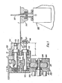
- the trimmer has two main parts: one, the trimming head, 100, mounted on the record press transfer means, such as a "sled", and the other, the drive means, 200, mounted on the record press frame.
- the drive means is mounted on the frame adjacent the record trimming position where a spindle and turntable, 300,. are provided to receive a disc for trimming.
- the trimming head is mounted on a transfer means or "sled” so that the head engages the drive means when the sled is at the "home" position, as hereinbefore described.
- a cross-section of a portion of a sled side member is shown at "S".
- the underside of member S is notched to accommodate a shaft, 101, of the trimming head.
- the trimming head has a frame of a U-shaped bracket having side limbs 111, 121, in which the shaft, 101, and parallel shaft, 105, are journalled by taper roller bearings held in place by circlips.
- the limbs are joined by a part, not shown, forming the base of the U and extending between them in a plane in front of and parallel to the drawing.
- the base of the U is slotted to receive the outer end of side member S.
- a bolt secures the bracket to the side member.
- the bracket is further secured by bolts which pass through side limb, 111, into member S.
- plate 131 is secured to side limb, 121, and abuts member S to stiffen side limb, 121, against movement.
- the U-shaped bracket is releasably mounted on the end of the sled and the mounting position is accurately repeatable by the engagement of the end of member S in the slotted base of the bracket.
- the arrangement described provides a rigid housing for the cutter wheels while being easily and accurately fitted to the record press.
- the shaft, 101 carries a large cutter wheel, 102, secured by bolt, 103, and collet, 104, and shaft, 105, carries a small cutter wheel 106, secured by bolt, 107, and collet, 108.
- wheel, 102 is of cylindrical form and wheel, 106, of conical form, as is well known in the art.
- Gears, 141 and 142 are keyed to shafts 101 and 105, respectively to couple the shafts for contra rotation at equal speed.
- Shaft, 105 also carries a gear, 143, which is engageable with a double-sided toothed belt, 201. Rotation of gear, 143, by a drive from belt, 201, causes cutter wheels, 102, 106, to rotate at equal speed in opposite direction.
- Thrust bearings, 112, 113 are provided on shafts 105 and 101.
- the drive means is powered by a suitable prime mover which in the illustrated embodiment includes an electric motor (210, Figure 2) and gear-box, not shown, which are mounted on the frame, not shown, of the record press.
- the output shaft, 202, of the gear-box carries a gear-wheel, 205, which is of a form to engage the inner toothed surface of the double-sided toothed belt, 201.
- a further idler gear-wheel is provided spaced from wheel, 205, in frame, 206.
- the belt, 201 extends with horizontal upper and lower sections between the gear-wheels.
- the frame, 206 is attached to the drive means by studs, 203, 204.
- the trimming head is shown in operative relation with the drive means and a record, 4, formed with flash, 41, attached and placed on spindle, 301, of the trimming station, 300.
- the record with flash attached is released to drop down spindle, 301, onto a small turntable, 302, by the action of the sled.
- gear-wheel, 143, of the trimming head, 100 into engagement with the toothed outer surface upper section of the double-sided belt, 201.
- the belt is driven by the rotation of gear-wheel, 205, to drive the cutter wheels, 102, 106, as mentioned above.
- the gear-wheel, 143 runs along the belt upper section as the sled returns to the "home" position so that the cutter wheels are turning as they engage the flash, 41, chordally to cut through it and drive the disc, 4, round on turntable, 302, to trim off the flash, 41, all the way round the disc.
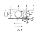
- the point at which the cutter wheels trim the flash is offset a small amount along a longitudinal axis of the press, e.g. 2 to 10 mm from the position of spindle, 301, (D in Figure 2).
- Figure 2 shows an outline of an automatic record press arranged as described above.
- the sled S transfers between three work stations viz. from shot forming, C, to pressing, P, to trimming, T, in known manner.
- the shot is extruded by extruder, E.
- the transfer portions 1, 2, 3, of the sled are at stations C, P and T respectively.
- the outward stroke, arrow 0, the extruded shot with labels applied from station C is transferred to pressing station P, and the disc 4 formed with flash 41 attached transferred from pressing station P, to trimming station T, the sled portions 1, 2, 3 moving to positions 1', 2', 3' respectively.
- any previously trimmed disc has been unloaded from trimming station T, in any suitable manner, not shown, but well known in the art, e.g. a vacuum transfer device.
- the trimming head, 100 engages the moving belt, 201, of drive means, 200, causing the cutter wheels to revolve.
- the trimming head cuts through the flash, 41, and causes the disc, 4, to turn..
- the trimming head stops so that the cutter wheels are about 4 mm short of the spindle; 301, (distance D).
- the continued movement of belt, 201; by drive means, 200 trims all the flash from the disc.
- a most important feature of the invention is the ease with which the trimming head is removable from the press without the need to dismantle the drive, etc.
- the cutting action of the cutting wheels can be set up away from the press and the prepared head simply clamped to the sled with only a short interruption to its operation, no adjustment being required as the position is set by the slotted bracket.
- the wearing parts, the cutter wheels, can be changed and sharpened without loss of press production as another trimming head can be installed meanwhile.
- the trimming head is.designed for long accurate use, the shaft bearings being preloaded against the cutting load and the cutting wheels have carbide cutting edges and surfaces. As the trimming head is only driven in the immediate vicinity of the trimmer, the wear is reduced and the cordal cutting line at which the wheels initially cut into the flash reduces the risk of "fold over" of the flash and failure to trim possible with an arcuate initial cutting line.
Landscapes
- Engineering & Computer Science (AREA)
- Mechanical Engineering (AREA)
- Details Of Cutting Devices (AREA)
- Processing And Handling Of Plastics And Other Materials For Molding In General (AREA)
- Moulds For Moulding Plastics Or The Like (AREA)
- Casting Or Compression Moulding Of Plastics Or The Like (AREA)
- Injection Moulding Of Plastics Or The Like (AREA)
- Grinding And Polishing Of Tertiary Curved Surfaces And Surfaces With Complex Shapes (AREA)
Applications Claiming Priority (2)
| Application Number | Priority Date | Filing Date | Title |
|---|---|---|---|
| GB4537177 | 1977-11-01 | ||
| GB4537177 | 1977-11-01 |
Publications (2)
| Publication Number | Publication Date |
|---|---|
| EP0001896A1 true EP0001896A1 (de) | 1979-05-16 |
| EP0001896B1 EP0001896B1 (de) | 1981-01-07 |
Family
ID=10436970
Family Applications (1)
| Application Number | Title | Priority Date | Filing Date |
|---|---|---|---|
| EP78300511A Expired EP0001896B1 (de) | 1977-11-01 | 1978-10-17 | Trimmen von Schallplatten |
Country Status (4)
| Country | Link |
|---|---|
| US (1) | US4235136A (de) |
| EP (1) | EP0001896B1 (de) |
| JP (1) | JPS5519590A (de) |
| DE (1) | DE2860434D1 (de) |
Cited By (1)
| Publication number | Priority date | Publication date | Assignee | Title |
|---|---|---|---|---|
| CN117260455A (zh) * | 2023-09-12 | 2023-12-22 | 广东众森实业发展有限公司 | 一种复合材料配件修边装置 |
Families Citing this family (5)
| Publication number | Priority date | Publication date | Assignee | Title |
|---|---|---|---|---|
| US4535223A (en) * | 1983-10-24 | 1985-08-13 | Rca Corporation | Apparatus for use in trimming molded records |
| DE3837688A1 (de) * | 1988-11-05 | 1990-05-10 | Leybold Ag | Vorrichtung zur bearbeitung von werkstuecken, vorzugsweise von kreisscheibenfoermigen, flachen substraten |
| JPH0737055B2 (ja) * | 1992-07-01 | 1995-04-26 | 椿本興業株式会社 | 成形装置 |
| US6843622B2 (en) * | 2002-02-14 | 2005-01-18 | Concept Design Electronics And Manufacturing, Inc. | Apparatus and method for profiling optical disks |
| CA2542755A1 (en) * | 2003-10-17 | 2005-04-28 | Medrx Co., Ltd. | Biguanide drug-containing jelly preparation |
Citations (3)
| Publication number | Priority date | Publication date | Assignee | Title |
|---|---|---|---|---|
| GB1192352A (en) * | 1966-04-15 | 1970-05-20 | Emi Ltd | Improvements relating to the Production of Gramophone Records |
| GB1261145A (en) * | 1969-09-19 | 1972-01-19 | Deutsche Grammophon Gmbh | Improvements in or relating to gramophone record manufacture |
| DE1779968B2 (de) * | 1964-08-24 | 1976-01-22 | Ausscheidung aus: 14 79 053 CBS Inc., New York, N.Y. (V.St.A.) | Vorrichtung zum herstellen von schallplatten |
Family Cites Families (5)
| Publication number | Priority date | Publication date | Assignee | Title |
|---|---|---|---|---|
| US3186029A (en) * | 1962-08-23 | 1965-06-01 | Metro Goldwyn Mayer Inc | Machine for making disk phonograph records |
| US3663136A (en) * | 1970-04-01 | 1972-05-16 | William S Westermann | Apparatus for automatically making phonograph records |
| DE2016749A1 (en) * | 1970-04-08 | 1971-10-21 | Capitol Records | Record manufacturing installation |
| US3862815A (en) * | 1973-07-20 | 1975-01-28 | Valley Metallurg Processing | Record producing apparatus |
| GB1529744A (en) * | 1976-04-22 | 1978-10-25 | Emi Ltd | Producing disc records |
-
1978
- 1978-10-17 EP EP78300511A patent/EP0001896B1/de not_active Expired
- 1978-10-17 DE DE7878300511T patent/DE2860434D1/de not_active Expired
- 1978-10-30 JP JP13367178A patent/JPS5519590A/ja active Granted
- 1978-10-30 US US05/955,573 patent/US4235136A/en not_active Expired - Lifetime
Patent Citations (3)
| Publication number | Priority date | Publication date | Assignee | Title |
|---|---|---|---|---|
| DE1779968B2 (de) * | 1964-08-24 | 1976-01-22 | Ausscheidung aus: 14 79 053 CBS Inc., New York, N.Y. (V.St.A.) | Vorrichtung zum herstellen von schallplatten |
| GB1192352A (en) * | 1966-04-15 | 1970-05-20 | Emi Ltd | Improvements relating to the Production of Gramophone Records |
| GB1261145A (en) * | 1969-09-19 | 1972-01-19 | Deutsche Grammophon Gmbh | Improvements in or relating to gramophone record manufacture |
Cited By (1)
| Publication number | Priority date | Publication date | Assignee | Title |
|---|---|---|---|---|
| CN117260455A (zh) * | 2023-09-12 | 2023-12-22 | 广东众森实业发展有限公司 | 一种复合材料配件修边装置 |
Also Published As
| Publication number | Publication date |
|---|---|
| DE2860434D1 (en) | 1981-02-26 |
| JPH0115365B2 (de) | 1989-03-16 |
| EP0001896B1 (de) | 1981-01-07 |
| JPS5519590A (en) | 1980-02-12 |
| US4235136A (en) | 1980-11-25 |
Similar Documents
| Publication | Publication Date | Title |
|---|---|---|
| US6637115B2 (en) | Pipe cutter | |
| GB1442800A (en) | Method and apparatus for accurate die-cutting | |
| EP0338015A1 (de) | Verfahren und vorrichtung zum schneiden und entgraten von rohren. | |
| GB1290619A (de) | ||
| EP0001896B1 (de) | Trimmen von Schallplatten | |
| GB1278725A (en) | Improvements in and relating to cutting devices | |
| EP0240972B1 (de) | Vorrichtung zum Querschneiden von Bahnen aus verformbarem Material | |
| CN213226510U (zh) | 可调节塑料板材宽度的切边装置 | |
| CN212887756U (zh) | 一种裁剪模具 | |
| CN2131676Y (zh) | 一种塑料切片机 | |
| CN216828990U (zh) | 一种基于伺服调刀的板材刮边总成 | |
| CN223477707U (zh) | 一种薄膜加工流水线的薄膜切边装置 | |
| CN223115319U (zh) | 一种尼龙膜分切加工装置 | |
| CN221437032U (zh) | Pin注塑预埋入自动上下料机 | |
| CN214733292U (zh) | 一种极耳分切装置 | |
| CN211102195U (zh) | 一种钢板剪切加工设备 | |
| CN113829426B (zh) | 一种弧形工件切除设备 | |
| SU1745441A1 (ru) | Устройство дл резки труб | |
| JPS6026889Y2 (ja) | 歯車面取り盤の自動段取り替え装置 | |
| CN108581050B (zh) | 一种加工发射天线钢带保护套的分剪机 | |
| GB1530004A (en) | Apparatus for chopping strip sheet material | |
| JPS55112754A (en) | Cutting method of block unit | |
| JPH0415452Y2 (de) | ||
| SU852626A1 (ru) | Устройство дл разделки конвейерныхлЕНТ | |
| KR200388839Y1 (ko) | 엣지 벤딩기의 가이드 롤러 자동 이송장치 |
Legal Events
| Date | Code | Title | Description |
|---|---|---|---|
| PUAI | Public reference made under article 153(3) epc to a published international application that has entered the european phase |
Free format text: ORIGINAL CODE: 0009012 |
|
| AK | Designated contracting states |
Designated state(s): DE FR GB |
|
| 17P | Request for examination filed | ||
| GRAA | (expected) grant |
Free format text: ORIGINAL CODE: 0009210 |
|
| AK | Designated contracting states |
Designated state(s): DE FR GB |
|
| REF | Corresponds to: |
Ref document number: 2860434 Country of ref document: DE Date of ref document: 19810226 |
|
| PGFP | Annual fee paid to national office [announced via postgrant information from national office to epo] |
Ref country code: FR Payment date: 19840831 Year of fee payment: 7 |
|
| REG | Reference to a national code |
Ref country code: GB Ref legal event code: 746 |
|
| PGFP | Annual fee paid to national office [announced via postgrant information from national office to epo] |
Ref country code: DE Payment date: 19881228 Year of fee payment: 11 |
|
| PG25 | Lapsed in a contracting state [announced via postgrant information from national office to epo] |
Ref country code: GB Effective date: 19891017 |
|
| GBPC | Gb: european patent ceased through non-payment of renewal fee | ||
| PG25 | Lapsed in a contracting state [announced via postgrant information from national office to epo] |
Ref country code: FR Effective date: 19900629 |
|
| PG25 | Lapsed in a contracting state [announced via postgrant information from national office to epo] |
Ref country code: DE Effective date: 19900703 |
|
| REG | Reference to a national code |
Ref country code: FR Ref legal event code: ST |
|
| PLBE | No opposition filed within time limit |
Free format text: ORIGINAL CODE: 0009261 |
|
| STAA | Information on the status of an ep patent application or granted ep patent |
Free format text: STATUS: NO OPPOSITION FILED WITHIN TIME LIMIT |